EP0186556A1 - Verteilersystem und -säule für elektrische Schaltanlagen - Google Patents
Verteilersystem und -säule für elektrische Schaltanlagen Download PDFInfo
- Publication number
- EP0186556A1 EP0186556A1 EP85402350A EP85402350A EP0186556A1 EP 0186556 A1 EP0186556 A1 EP 0186556A1 EP 85402350 A EP85402350 A EP 85402350A EP 85402350 A EP85402350 A EP 85402350A EP 0186556 A1 EP0186556 A1 EP 0186556A1
- Authority
- EP
- European Patent Office
- Prior art keywords
- sectioning
- support
- faceplate
- bars
- fixing
- Prior art date
- Legal status (The legal status is an assumption and is not a legal conclusion. Google has not performed a legal analysis and makes no representation as to the accuracy of the status listed.)
- Granted
Links
- 230000001681 protective effect Effects 0.000 claims abstract description 14
- 239000000523 sample Substances 0.000 claims description 23
- 238000013519 translation Methods 0.000 claims description 6
- 230000000903 blocking effect Effects 0.000 claims description 5
- 238000010079 rubber tapping Methods 0.000 abstract 1
- 239000004020 conductor Substances 0.000 description 7
- 238000001514 detection method Methods 0.000 description 4
- 238000006073 displacement reaction Methods 0.000 description 2
- 238000000638 solvent extraction Methods 0.000 description 2
- 229910000746 Structural steel Inorganic materials 0.000 description 1
- 244000245420 ail Species 0.000 description 1
- 238000010276 construction Methods 0.000 description 1
- 238000003780 insertion Methods 0.000 description 1
- 230000037431 insertion Effects 0.000 description 1
- 239000011810 insulating material Substances 0.000 description 1
- 230000003993 interaction Effects 0.000 description 1
- 239000000463 material Substances 0.000 description 1
- 238000012986 modification Methods 0.000 description 1
- 230000004048 modification Effects 0.000 description 1
- 230000007935 neutral effect Effects 0.000 description 1
- 238000005192 partition Methods 0.000 description 1
- 125000006850 spacer group Chemical group 0.000 description 1
- 238000012360 testing method Methods 0.000 description 1
- 230000009466 transformation Effects 0.000 description 1
Images



Classifications
-
- H—ELECTRICITY
- H02—GENERATION; CONVERSION OR DISTRIBUTION OF ELECTRIC POWER
- H02B—BOARDS, SUBSTATIONS OR SWITCHING ARRANGEMENTS FOR THE SUPPLY OR DISTRIBUTION OF ELECTRIC POWER
- H02B1/00—Frameworks, boards, panels, desks, casings; Details of substations or switching arrangements
- H02B1/20—Bus-bar or other wiring layouts, e.g. in cubicles, in switchyards
- H02B1/21—Bus-bar arrangements for rack-mounted devices with withdrawable units
-
- H—ELECTRICITY
- H02—GENERATION; CONVERSION OR DISTRIBUTION OF ELECTRIC POWER
- H02B—BOARDS, SUBSTATIONS OR SWITCHING ARRANGEMENTS FOR THE SUPPLY OR DISTRIBUTION OF ELECTRIC POWER
- H02B1/00—Frameworks, boards, panels, desks, casings; Details of substations or switching arrangements
- H02B1/20—Bus-bar or other wiring layouts, e.g. in cubicles, in switchyards
- H02B1/205—Bus-bar or other wiring layouts, e.g. in cubicles, in switchyards for connecting electrical apparatus mounted side by side on a rail
-
- H—ELECTRICITY
- H02—GENERATION; CONVERSION OR DISTRIBUTION OF ELECTRIC POWER
- H02B—BOARDS, SUBSTATIONS OR SWITCHING ARRANGEMENTS FOR THE SUPPLY OR DISTRIBUTION OF ELECTRIC POWER
- H02B11/00—Switchgear having carriage withdrawable for isolation
-
- H—ELECTRICITY
- H02—GENERATION; CONVERSION OR DISTRIBUTION OF ELECTRIC POWER
- H02G—INSTALLATION OF ELECTRIC CABLES OR LINES, OR OF COMBINED OPTICAL AND ELECTRIC CABLES OR LINES
- H02G5/00—Installations of bus-bars
- H02G5/06—Totally-enclosed installations, e.g. in metal casings
- H02G5/08—Connection boxes therefor
Definitions
- the present invention relates to a distribution system for electrical switch devices, this system comprising a distribution column comprising non-coplanar vertical bus bars and a protective envelope disposed around the bars. It also relates to the distribution column suitable for such a system.
- electrical switch devices we currently designate devices such as contactors, circuit breakers, contactor breakers, protective devices, or switches proper comprising several poles for opening and / or closing a power circuit supplied with from the aforementioned distribution bus bars.
- the object of the present invention is in particular to allow space-saving fixing and a sectionable electrical connection of switching devices on a distribution column with non-coplanar bus bars.
- a plurality of supports which extend in a direction parallel to the planes of the bars, each support comprising at least one bearing wall applicable on a respective face for fixing the the protective casing of the column and being arranged to carry, on the one hand, at least one switching device, on the other hand, a socket outlet and sectioning member provided with plug-in clamps on the distribution bars by introduction in hatches provided in a side of the envelope perpendicular to the planes of the bars, the current-taking and sectioning member comprising means for connection to switch devices and a movable sectioning part capable of being actuated by manual control means.
- the system described consists of supports, each of which comprises at least one switching device and one sectioning member associated in the form of a block attached to the support; the supports are arranged as many horizontal branches either unilaterally on one side of the envelope perpendicular to the bar planes, or bilaterally on two such opposite sides of the envelope; fixing wings are also provided on the casing parallel to the planes of the bars to allow mounting of the supports by frontal presentation, application against the wings and fixing to them by means of centering and locking pieces, these pieces being integral with the support or the envelope and cooperating with orifices provided in the fixing wings of the envelope or of the support respectively.
- the support comprises a fixed part relative to the casing of the column and a part adjustable in depth relative to the fixed part to allow the mounting of switchgear of different types and dimensions by means of the same support and in the same frontal template. It is thus possible optionally to fix modular devices on a vertical or horizontal rail, or on several such rails, attached to the adjustable part of the support.
- the faceplate can, moreover, be arranged to comprise manual means of sectioning control, fixed or for example constituted by a key.
- the faceplate When the manual sectioning control means comprise a key, the faceplate has an orifice key insertion slots and a rotary key housing nut and drive of a disconnection control shaft; the nut has at least one bearing capable of cooperating with a stop of the probe to be locked in rotation by the stop when the probe detects that the switch device is in the closed position.
- the faceplate may finally have elements indicating the severed or reset state of the sectioning block, these elements being very simply arranged on the rotary nut to appear in a window of the faceplate.
- a precut device associated with the switch device and sensitive to the movement of the faceplate or preferably to a member moved during the actuation of the means of manual sectioning control.
- the invention also relates to the distribution column arranged to receive the modular supports of the system described above.
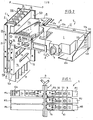
- the system S illustrated in FIG. 1 is associated with a distribution column C comprising non-coplanar bus bars Bl to B5, parallel to the same plane P in a protective envelope E.
- the system shown is designed for the attachment and electrical connection of switch devices I, for example contactors, circuit breakers, contactor breakers or switches proper, with which are possibly associated non-represented devices such as protection auxiliaries, fuses, remote control auxiliaries.
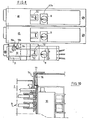
- the S system consists of supports forming M modules; Figure 1 shows several supports Ml-M6 arranged bilaterally relative to the column on the opposite sides thereof.
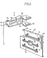
- Each support or module M is of generally elongated shape and comprises a fixed part 11 and a plate 12 adjustable in depth, that is to say perpendicular to the planes of the bars, relative to the fixed part ( Figures 2, 3 and 4); it also includes, if necessary, at least one square 13 increasing the depth adjustment latitude, this square being fixed to the plate 12 (FIG. 4); the plate 12 allows to keep, with devices of different depths, a housing template located at the rear of a Pl-Pl plane ( Figure 4) corresponding for example to a cabinet door housing the described distribution system.
- the brackets 13 can for example support vertical or horizontal rails themselves carrying modular switch devices and their annexes (Figure 3).
- the plate 12 is preferably a profile or chassis provided with standardized perforations 12a in a core 12b bordered by wings 12c, 12d there are provided on its wings 12c, 12d fixing holes 12e allowing the passage of screws which also pass through adjustment orifices, for example in the form of buttonholes 11a, formed on an upper horizontal wall 11b of the fixed support 11.
- the bracket 13 has orifices 13a corresponding to orifices 12e of the plate in order to produce an adjustable fixing in depth of the bracket 13 by means of screws engaged in said orifices, this allowing modular devices to be fitted to the support with less depth than devices I.
- the plate 12 has a surface developed vertically to carry by means of telescopic legs 74 frontally attached to several horizontal rails 75 for supporting modular devices.
- the fixed support 11 has an upper horizontal wall llb and a lower horizontal wall llc comprising the abovementioned adjustment buttonholes lla for the plate 12.
- the walls llb, llc are joined by a vertical veil lld provided with an opening intended to be placed opposite a hatch formed in a side of the column to allow the passage of blades or skewers on the bars B1-B5.
- the fixed support 11 comprises a front wall llf and a rear wall llg for attachment to the casing E of the column C.
- the walls llf, llg are vertical and are attached at right angles to the vertical veil lld the wall llf is equipped with a tenon llh and a locking piece lli of any type, for example quarter turn.
- the wall llg is provided with two studs llh; the tenons llh have frustoconical ends to be suitably guided in housings of the envelope E.
- the protective envelope E in column C contains the bus bars B1-B5. It comprises (FIGS. 2 and 3) two opposite vertical flanks 14, 15 perpendicular to the plane PP and each provided with hatches 16 for the passage of racking clamps specific to each support M. To each of the vertical flanks 14, 15 is attached a folded front wing 14a, 15a and a folded rear wing 14b, 15b. A U-shaped profile 17 is fixed inside the casing E on the internal faces of the vertical walls 14, 15, so as to provide a chamber 18 set back from the wings 14a, 15a, while a dish 19 is fixed behind the wings 14b, 15b to close the chamber 22 of the bars B1-B5.
- the wings 14a, 14b, 15a, 15b are parallel to the plane PP and are provided, at regular intervals h corresponding to the pitch of attachment of the modular supports, with holes 20 for passage for the pins llh and holes 21 for passage for the locking parts lli. It is understood that the supports M are engaged horizontally on the column in a frontal manner, that is to say in a direction perpendicular to the plane PP and to the planes of the bus bars Bl-B5, so that the pins llh and the pieces of locking lli penetrate into the respective orifices 20, 21 of the wings 14a, 14b, 15a, 15b.
- the sides 14, 15 of the envelope E may advantageously have projections 72, for example obtained by a puncture, to serve as a support for the support 11 and to facilitate the positioning of the latter.
- the bars B are five in number but can, of course, be fewer. Bars Bl to B5 correspond to the conductors of a three-phase electrical network with distributed neutral and protective conductor.
- the protective conductor can consist of the envelope E itself when the latter is made of electrically conductive material, or by a protective conductor attached to the envelope when the latter is made of material insulating. This latter embodiment will be described later with reference to FIG. 10.
- the outlet and sectioning member is a block 30 attached to the fixed support 11 by means of fixing means, but it could of course itself constitute this fixed support and / or consist of a member socket outlet and a sectioning device.
- the vertical veil lld of the fixed support 11 can be fixed to the side 14 of the envelope E.
- the block 30 is molded in insulating material and has pliers 31 for plugging in the current socket onto the bus bars B1-B5 and withdrawable therefrom by translation of a single-section slide 32 controlled by a rotary shaft 33; the clamps 31 are housed individually in compartments formed in the slide 32.
- the block 30 has, on the other hand, fixed means of connection, for example by screw with power terminals of the switching device I.
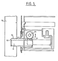
- the control of the movement of translation of the slide takes place in response to the rotation of the shaft 33 by means of at least one movement transformation link, for example of the pinion and rack type.
- FIG. 5 represents this type of connection with the pinion 35 mounted on the rotary shaft 33 and meshing with the rack 36 produced on the upper face of the slide 32, so as to transform the rotational movement of the shaft into a movement of translation of the slide; in Figure 5, the clamp 31 is illustrated in the plugged-in position on the busbar B2 for example.
- the rotation of the shaft 33 is produced by means of a key, not shown, the imprint of which can penetrate into an appropriate housing 43 of a nut 40 fixed to the shaft (FIG. 4).
- This nut 40 can be guided axially on the shaft 33 and be urged towards a section faceplate 50 by a spring 41, so as to be capable of a slight axial stroke towards the rear relative to the shaft 33 during the introduction of the sectioning control key in order to actuate a precut contact 42 associated with the switch device I so as to ensure that the sectioning will be carried out empty.
- the sectioning faceplate 50 is fixed for example by snap-fastening on the front face of the sectioning block 30 or of the fixed support 11.
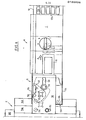
- This faceplate 50 comprises (FIG. 4) a feeler 51 which can be moved manually parallel to the plane Pl-Pl in an arrow A against the force of an unspecified return spring.
- the probe is housed and guided in the faceplate, being provided with a manual displacement member.
- This member is for example a button 52 for maneuvering through an oblong window 53 of the faceplate ( Figures 2 and 6) or a socket 52 formed by a withdrawal of the probe ( Figures 8 and 9).
- the free end of the probe can thus be brought from the rest position 1 to the detection position 2 "on” or “closing” or to the detection position 3 "cut", "tripping” or “opening” from the position taken by button B of the switching device I.
- the probe 51 also has an unspecified stop cooperating with a bearing, for example a cam 44 of the nut 40 to prevent cutting and re-engagement when the probe can only come 'in position 2.
- Rotary detection can of course also be carried out.
- Sensors 51 of different shapes can be provided in association with switch devices of different dimensions and / or switch devices equipped with buttons or handles arranged differently.
- the front face of the faceplate has on the other hand a slotted orifice 55 for the introduction of the cutting and resetting control key, an indication window 56 opposite which comes an indication "0" or "1" carried by a face integral in rotation with the shaft 33, for example the front face of the nut 40, and an oblong window 57 capable of coinciding with a corresponding window 58 of the nut to allow padlocking or locking of the shaft 33 in its sectioning position.
- the nut 40 has been illustrated in FIG. 6 in solid lines in its sectioning position and in broken lines in its rearming position.
- the shape of the key and the hole 55 ensures that the key can only be engaged and removed in the two positions “sectioned” and “reset” by quarter-turn rotation to go from one to the other, notably prohibiting the withdrawal of the key in its intermediate position.
- the power wiring downstream of the switch device and its possible control wiring can easily be collected laterally to the modular supports M.
- the system shown can be installed independently or in a distribution cabinet.
- horizontal insulating partitions 60a are provided between the various supports M (FIGS. 1 and 2).
- each support M is housed in a box 60 comprising a bottom wall 61, a front wall 62, an upper wall 63 and a lower wall 64, as well as on the side opposite the fixed part 11 of the support two spacers 65, 66 and a side wall 67.
- the rigidity of the walls 62, 67 of the box combined with that of the support M provides the desired mechanical strength of the assembly.
- the walls 63 and 64 have hinges 63a, 64a for a pivoting door 68.
- the front wall 62 forms a device faceplate for the switching devices and comprises at least one window 62a to leave visible the button B of each device, while being shaped and mounted so as to leave accessible the cutting faceplate 50 and the probe. 51 ( Figures 7 and 8).
- the door 68 has an opening 68a allowing access to the button B and to the socket 52 for operating the probe 51.
- the probe is moreover provided with an orifice allowing the padlocking of the probe in the open position 3 of the switch device; it can be seen that the operator can thus carry out a test of the button B and a locking in the open state of the device without having to open the door 68, the blocking unit being able to remain connected.
- Certain walls of the cabinet for example the bottom wall 64, can play the role of partitioning in a cabinet.
- a window 71 allowing the operator to observe the actual cut-off using indicator means linked to the movable part of the block 30 and appearing in this window in the sectioning position.
- a padlock 73 has been shown engaged in an orifice 40a of the nut 40 and in a corresponding orifice 70 of the sectioning faceplate 50.
- the faceplate 50 has at its rear part a facet 50a which masks a screw not shown for fixing the appliance faceplate 62 to the support.
- the faceplate 50 is retractable, for example by pivoting about an axis 50b, to release the fixing screw. It is understood that the intervention on the switch device I or the disassembly thereof is therefore only authorized after the pivoting of the sectioning faceplate 50 to disassemble the device faceplate 62.
- the pivoting the faceplate 50 to come into the open position 50c is only possible in the sectioning position of the movable part of the block 30; cooperating conformations are provided for this purpose on the faceplate and the mobile part, for example the nut 40, of the block 30 to prevent the opening of the faceplate 50 in the plugged-in position.
- the casing E of the distribution column illustrated in FIG. 10 houses several bars B and has, on its rear external part, an added angle 76. On this angle iron is fixed on the side of the blocking block 30 a flat conductor 77 of protection; this conductor 77 is optionally arranged and it is brought into contact in the plugging-in position of the block 30 with an elastic conductive part 78 provided on the block.
- the operator grasps the button or the socket 52 and moves the probe 51 in the direction of the arrow A (FIGS. 2 and 4) until the end of the probe end against the button B of switch device I.
- the operator can insert the cutting control key into the slot 55 and in the corresponding coaxial housing 43 of the nut 40, the respective slots of the orifice and of the housing being aligned.
- the operator then produces the pivoting of the shaft and the displacement of the slide 32.
- the precut microswitch 42 is actuated by the rearward movement of the nut 40 against the return spring 41 when the operator enters the key. The operator can then safely operate the interrupted device 1 and check the auxiliaries thereof.
Landscapes
- Power Engineering (AREA)
- Engineering & Computer Science (AREA)
- Patch Boards (AREA)
- Remote Monitoring And Control Of Power-Distribution Networks (AREA)
- Variable-Direction Aerials And Aerial Arrays (AREA)
- Supply And Distribution Of Alternating Current (AREA)
- Electronic Switches (AREA)
- Trip Switchboards (AREA)
- Near-Field Transmission Systems (AREA)
- Vehicle Body Suspensions (AREA)
- Arrangements For Transmission Of Measured Signals (AREA)
- Switches With Compound Operations (AREA)
- Geophysics And Detection Of Objects (AREA)
- Transmitters (AREA)
- Driving Mechanisms And Operating Circuits Of Arc-Extinguishing High-Tension Switches (AREA)
Priority Applications (1)
| Application Number | Priority Date | Filing Date | Title |
|---|---|---|---|
| AT85402350T ATE43207T1 (de) | 1984-12-20 | 1985-11-29 | Verteilersystem und -saeule fuer elektrische schaltanlagen. |
Applications Claiming Priority (2)
| Application Number | Priority Date | Filing Date | Title |
|---|---|---|---|
| FR8419536 | 1984-12-20 | ||
| FR8419536A FR2575340B1 (fr) | 1984-12-20 | 1984-12-20 | Systeme et colonne de distribution pour appareils interrupteurs |
Publications (2)
| Publication Number | Publication Date |
|---|---|
| EP0186556A1 true EP0186556A1 (de) | 1986-07-02 |
| EP0186556B1 EP0186556B1 (de) | 1989-05-17 |
Family
ID=9310825
Family Applications (1)
| Application Number | Title | Priority Date | Filing Date |
|---|---|---|---|
| EP85402350A Expired EP0186556B1 (de) | 1984-12-20 | 1985-11-29 | Verteilersystem und -säule für elektrische Schaltanlagen |
Country Status (10)
| Country | Link |
|---|---|
| US (1) | US4668035A (de) |
| EP (1) | EP0186556B1 (de) |
| JP (1) | JPS61154410A (de) |
| AT (1) | ATE43207T1 (de) |
| CA (1) | CA1262182A (de) |
| DE (1) | DE3570333D1 (de) |
| ES (1) | ES8702746A1 (de) |
| FR (1) | FR2575340B1 (de) |
| NO (1) | NO164148C (de) |
| SG (1) | SG101590G (de) |
Cited By (10)
| Publication number | Priority date | Publication date | Assignee | Title |
|---|---|---|---|---|
| EP0708512A1 (de) * | 1994-10-21 | 1996-04-24 | Holec Systemen En Componenten B.V. | Innenraumsystem für einen Schaltschrank |
| GB2310768A (en) * | 1996-01-31 | 1997-09-03 | Schneider Ltd | Distribution equipment for a wall mountable consumer unit |
| EP0788205A3 (de) * | 1996-01-31 | 1997-12-17 | Schneider Electric Sa | Verbesserung von elektrischen Verteilungsgeräten |
| EP0884814A1 (de) * | 1997-05-16 | 1998-12-16 | ABB SACE S.p.A. | Modularer Adapter für elektrische Vorrichtungen |
| DE19738705A1 (de) * | 1997-08-29 | 1999-03-04 | Siemens Ag | Verteilungssystem der Energietechnik mit einem Geräteeinsatz |
| US5905631A (en) * | 1995-03-28 | 1999-05-18 | Klockner-Moeller Gmbh | Low-voltage switchgear assembly for the output or distribution of electrical energy |
| RU2251771C1 (ru) * | 2001-04-20 | 2005-05-10 | Сименс Акциенгезелльшафт | Устройство подключения для камеры распределительного устройства с выдвижными приборными блоками |
| CN103560426A (zh) * | 2013-11-08 | 2014-02-05 | 张家港市天鸿机电有限公司 | 一种抽出式低压开关柜壳体的四分之一单元抽屉 |
| CN103579940A (zh) * | 2013-11-07 | 2014-02-12 | 江苏天港箱柜有限公司 | 高低压配电柜中垂直铜排与插件的连接结构 |
| CN106300120A (zh) * | 2015-05-11 | 2017-01-04 | 江苏中自电气技术有限公司 | 一种带定位支撑件的低压抽屉柜抽屉回路操作系统 |
Families Citing this family (12)
| Publication number | Priority date | Publication date | Assignee | Title |
|---|---|---|---|---|
| FR2593322B1 (fr) * | 1986-01-22 | 1991-04-19 | Telemecanique Electrique | Dispositif de prise de courant sectionnable sur une colonne de distribution a barres omnibus |
| DE3939355A1 (de) * | 1989-11-24 | 1991-05-29 | Siemens Ag | Elektrische schaltanlage mit einem ein- und ausfahrbaren geraetetraeger |
| DE102005003199A1 (de) * | 2004-08-24 | 2006-03-02 | Weidmüller Interface GmbH & Co. KG | Montage- und Anschluß-System für elektrische Geräte |
| US8203828B2 (en) | 2005-01-27 | 2012-06-19 | Production Resource Group Llc | Portable power and signal distribution system for a controllable system including multiple devices |
| JP4578273B2 (ja) * | 2005-02-28 | 2010-11-10 | 三菱電機株式会社 | コントロールセンタの機能ユニット及びその製造方法 |
| JP2008099498A (ja) * | 2006-10-16 | 2008-04-24 | Meidensha Corp | コントロールセンタユニット |
| US8671556B1 (en) | 2009-07-09 | 2014-03-18 | Finley Lee Ledbetter | Remote racking tool |
| DE102011003208B4 (de) * | 2011-01-26 | 2016-05-25 | Senvion Gmbh | Turm einer Windenergieanlage mit Stromleitmitteln |
| BR102014007562B1 (pt) * | 2014-03-28 | 2021-12-28 | Melquisedec Francisquini | Centro de controle de motores |
| EP3454437A1 (de) * | 2017-09-11 | 2019-03-13 | ABB S.p.A. | Elektrische niederspannungsschalttafel |
| US10965072B2 (en) | 2018-09-10 | 2021-03-30 | Eaton Intelligent Power Limited | Remote racking device for bus plug |
| CN113286480B (zh) * | 2021-05-24 | 2022-09-20 | 北京广利核系统工程有限公司 | 机箱的固定装置及电器设备 |
Citations (3)
| Publication number | Priority date | Publication date | Assignee | Title |
|---|---|---|---|---|
| US3321672A (en) * | 1964-12-31 | 1967-05-23 | Westinghouse Electric Corp | Control center housing structure |
| US3626253A (en) * | 1970-05-06 | 1971-12-07 | Zinsco Electrical Products | Cell construction for motor control center for separate disengaging of terminal blocks and bus stabs |
| FR2126115A3 (de) * | 1971-02-26 | 1972-10-06 | Memn |
Family Cites Families (6)
| Publication number | Priority date | Publication date | Assignee | Title |
|---|---|---|---|---|
| US3067402A (en) * | 1961-04-05 | 1962-12-04 | Norrich Plastic Corp | Safety plug lock |
| US3217211A (en) * | 1961-10-16 | 1965-11-09 | Fed Pacific Electric Co | Electrical control apparatus |
| US3634810A (en) * | 1970-02-03 | 1972-01-11 | Reynolds Metals Co | Electrical bus bar construction and method of making same |
| US4032209A (en) * | 1976-01-15 | 1977-06-28 | Appleton Electric Company | Multiple socket assembly for electrical components |
| JPS5833908A (ja) * | 1981-08-18 | 1983-02-28 | 三菱電機株式会社 | コントロ−ルセンタ |
| US4531174A (en) * | 1981-10-27 | 1985-07-23 | Square D Company | Draw-out circuit breaker with improved external connectors |
-
1984
- 1984-12-20 FR FR8419536A patent/FR2575340B1/fr not_active Expired
-
1985
- 1985-11-29 AT AT85402350T patent/ATE43207T1/de not_active IP Right Cessation
- 1985-11-29 EP EP85402350A patent/EP0186556B1/de not_active Expired
- 1985-11-29 DE DE8585402350T patent/DE3570333D1/de not_active Expired
- 1985-12-17 NO NO855099A patent/NO164148C/no unknown
- 1985-12-17 CA CA000497921A patent/CA1262182A/fr not_active Expired
- 1985-12-18 US US06/810,124 patent/US4668035A/en not_active Expired - Lifetime
- 1985-12-20 JP JP60287576A patent/JPS61154410A/ja active Granted
- 1985-12-20 ES ES550222A patent/ES8702746A1/es not_active Expired
-
1990
- 1990-12-21 SG SG1015/90A patent/SG101590G/en unknown
Patent Citations (3)
| Publication number | Priority date | Publication date | Assignee | Title |
|---|---|---|---|---|
| US3321672A (en) * | 1964-12-31 | 1967-05-23 | Westinghouse Electric Corp | Control center housing structure |
| US3626253A (en) * | 1970-05-06 | 1971-12-07 | Zinsco Electrical Products | Cell construction for motor control center for separate disengaging of terminal blocks and bus stabs |
| FR2126115A3 (de) * | 1971-02-26 | 1972-10-06 | Memn |
Cited By (13)
| Publication number | Priority date | Publication date | Assignee | Title |
|---|---|---|---|---|
| EP0708512A1 (de) * | 1994-10-21 | 1996-04-24 | Holec Systemen En Componenten B.V. | Innenraumsystem für einen Schaltschrank |
| NL9401755A (nl) * | 1994-10-21 | 1996-06-03 | Holec Syst & Componenten | Interieursysteem voor een schakelkast. |
| US5905631A (en) * | 1995-03-28 | 1999-05-18 | Klockner-Moeller Gmbh | Low-voltage switchgear assembly for the output or distribution of electrical energy |
| EP0788205A3 (de) * | 1996-01-31 | 1997-12-17 | Schneider Electric Sa | Verbesserung von elektrischen Verteilungsgeräten |
| GB2310768A (en) * | 1996-01-31 | 1997-09-03 | Schneider Ltd | Distribution equipment for a wall mountable consumer unit |
| EP0884814A1 (de) * | 1997-05-16 | 1998-12-16 | ABB SACE S.p.A. | Modularer Adapter für elektrische Vorrichtungen |
| DE19738705A1 (de) * | 1997-08-29 | 1999-03-04 | Siemens Ag | Verteilungssystem der Energietechnik mit einem Geräteeinsatz |
| RU2213402C2 (ru) * | 1997-08-29 | 2003-09-27 | Сименс Акциенгезелльшафт | Энергетическая распределительная система со съемным приборным блоком |
| RU2251771C1 (ru) * | 2001-04-20 | 2005-05-10 | Сименс Акциенгезелльшафт | Устройство подключения для камеры распределительного устройства с выдвижными приборными блоками |
| CN103579940A (zh) * | 2013-11-07 | 2014-02-12 | 江苏天港箱柜有限公司 | 高低压配电柜中垂直铜排与插件的连接结构 |
| CN103579940B (zh) * | 2013-11-07 | 2015-10-28 | 江苏天港箱柜有限公司 | 高低压配电柜中垂直铜排与插件的连接结构 |
| CN103560426A (zh) * | 2013-11-08 | 2014-02-05 | 张家港市天鸿机电有限公司 | 一种抽出式低压开关柜壳体的四分之一单元抽屉 |
| CN106300120A (zh) * | 2015-05-11 | 2017-01-04 | 江苏中自电气技术有限公司 | 一种带定位支撑件的低压抽屉柜抽屉回路操作系统 |
Also Published As
| Publication number | Publication date |
|---|---|
| DE3570333D1 (en) | 1989-06-22 |
| NO164148C (no) | 1990-08-29 |
| SG101590G (en) | 1991-08-23 |
| NO164148B (no) | 1990-05-21 |
| JPH0576244B2 (de) | 1993-10-22 |
| JPS61154410A (ja) | 1986-07-14 |
| ATE43207T1 (de) | 1989-06-15 |
| US4668035A (en) | 1987-05-26 |
| FR2575340A1 (fr) | 1986-06-27 |
| ES550222A0 (es) | 1987-01-01 |
| ES8702746A1 (es) | 1987-01-01 |
| FR2575340B1 (fr) | 1987-02-06 |
| CA1262182A (fr) | 1989-10-03 |
| NO855099L (no) | 1986-06-23 |
| EP0186556B1 (de) | 1989-05-17 |
Similar Documents
| Publication | Publication Date | Title |
|---|---|---|
| EP0186556B1 (de) | Verteilersystem und -säule für elektrische Schaltanlagen | |
| EP0236179B1 (de) | Mechanismus zum Schnappen und Trennen eines elektrischen Schalters mit Haupt- und Hilfsschaltkreisen | |
| CA2019138A1 (fr) | Platine amovible de support d'appareils electriques pour dispositif repartiteur de puissance | |
| EP1331712A1 (de) | Elektrisches Gerät zur Befestigung auf einer Hutprofiltragschiene | |
| EP0233420B1 (de) | Trennbare Stromentnahmevorrichtung auf einer Verteilsäule mit Sammelschiene | |
| EP2538493B1 (de) | Elektrische Anschlussvorrichtung mindestens eines Leiters an mindestens einen Kontaktbereich eines elektrischen Geräts und elektrisches Gerät, das damit ausgestattet ist | |
| FR2646568A1 (en) | Electrical distribution panel equipped with isolators | |
| FR2513006A1 (fr) | Dispositif interrupteur modulaire a poles multiples | |
| EP3041021B1 (de) | Modulares gerät mit erhöhter sicherheit, und selbstgeschützte elektrische anlage, die ein solches modulares gerät verbunden mit einem schutzschalter umfasst | |
| EP0030489B1 (de) | In der Fabrik vorgefertigte elektrische Mittelspannungsschaltanlage und Verfahren zu ihrer Montage | |
| FR2622734A1 (fr) | Boitier pour appareil de coupure, notamment disjoncteur ou interrupteur, utilisable en atmosphere explosible | |
| EP2369699A1 (de) | Elektrischer Verteiler- oder Schaltkasten, der eine entfernbare Schienenauflagerung für die Montage von elektrischen Geräten umfasst | |
| EP3041022A1 (de) | Modulares gerät mit einziehbarem verbindungszapfen, und selbstgeschützte elektrische anlage, die ein solches modulares gerät verbunden mit einem schutzschalter umfasst | |
| EP4106120A1 (de) | Abzweigkasten für sammelschienen | |
| FR2708392A1 (fr) | Cellule moyenne tension sous enveloppe métallique avec disjoncteur auto-sectionneur. | |
| EP4106122B1 (de) | Abzweigkasten für sammelschienen | |
| EP4348692B1 (de) | Anordnung mit einem elektronischen auslöser und einem kontaktmodul | |
| EP4106121B1 (de) | Abzweigkasten für sammelschienen | |
| EP2320532B1 (de) | Vorrichtung zur Montage eines Pfostens am hinteren Teil eines Stromverteilungskastens, und mit einer solchen Vorrichtung ausgestatteter Stromverteilungskasten | |
| EP4256662B1 (de) | Einschub für schaltgerät und baugruppe beinhaltend einen solchen einschub und ein solches schaltgerät | |
| EP2750157B1 (de) | Selektiver Schutzschalter in einem modularen Gehäuse | |
| FR2594266A1 (fr) | Mecanisme d'embrochage et de debrochage d'un disjoncteur electrique a systeme de blocage du support mecanique mobile. | |
| EP2693579A1 (de) | Stromverteilungsschiene für elektrische Leitungsschutzgeräte | |
| EP0128130A2 (de) | Gekapselte Zelle mit ausziehbarem Lasttrennschalter | |
| EP0064904B1 (de) | Schrank oder Gehäuse für steckbare elektrische Geräte |
Legal Events
| Date | Code | Title | Description |
|---|---|---|---|
| PUAI | Public reference made under article 153(3) epc to a published international application that has entered the european phase |
Free format text: ORIGINAL CODE: 0009012 |
|
| 17P | Request for examination filed |
Effective date: 19851202 |
|
| AK | Designated contracting states |
Kind code of ref document: A1 Designated state(s): AT BE CH DE FR GB IT LI NL |
|
| 17Q | First examination report despatched |
Effective date: 19880311 |
|
| GRAA | (expected) grant |
Free format text: ORIGINAL CODE: 0009210 |
|
| AK | Designated contracting states |
Kind code of ref document: B1 Designated state(s): AT BE CH DE FR GB IT LI NL |
|
| REF | Corresponds to: |
Ref document number: 43207 Country of ref document: AT Date of ref document: 19890615 Kind code of ref document: T |
|
| GBT | Gb: translation of ep patent filed (gb section 77(6)(a)/1977) | ||
| ITF | It: translation for a ep patent filed | ||
| REF | Corresponds to: |
Ref document number: 3570333 Country of ref document: DE Date of ref document: 19890622 |
|
| PLBE | No opposition filed within time limit |
Free format text: ORIGINAL CODE: 0009261 |
|
| STAA | Information on the status of an ep patent application or granted ep patent |
Free format text: STATUS: NO OPPOSITION FILED WITHIN TIME LIMIT |
|
| 26N | No opposition filed | ||
| ITTA | It: last paid annual fee | ||
| PGFP | Annual fee paid to national office [announced via postgrant information from national office to epo] |
Ref country code: NL Payment date: 19981020 Year of fee payment: 14 |
|
| PGFP | Annual fee paid to national office [announced via postgrant information from national office to epo] |
Ref country code: AT Payment date: 19981021 Year of fee payment: 14 |
|
| PGFP | Annual fee paid to national office [announced via postgrant information from national office to epo] |
Ref country code: CH Payment date: 19981119 Year of fee payment: 14 |
|
| PGFP | Annual fee paid to national office [announced via postgrant information from national office to epo] |
Ref country code: BE Payment date: 19981210 Year of fee payment: 14 |
|
| PG25 | Lapsed in a contracting state [announced via postgrant information from national office to epo] |
Ref country code: AT Free format text: LAPSE BECAUSE OF NON-PAYMENT OF DUE FEES Effective date: 19991129 |
|
| PG25 | Lapsed in a contracting state [announced via postgrant information from national office to epo] |
Ref country code: LI Free format text: LAPSE BECAUSE OF NON-PAYMENT OF DUE FEES Effective date: 19991130 Ref country code: CH Free format text: LAPSE BECAUSE OF NON-PAYMENT OF DUE FEES Effective date: 19991130 Ref country code: BE Free format text: LAPSE BECAUSE OF NON-PAYMENT OF DUE FEES Effective date: 19991130 |
|
| BERE | Be: lapsed |
Owner name: LA TELEMECANIQUE ELECTRIQUE Effective date: 19991130 |
|
| PG25 | Lapsed in a contracting state [announced via postgrant information from national office to epo] |
Ref country code: NL Free format text: LAPSE BECAUSE OF NON-PAYMENT OF DUE FEES Effective date: 20000601 |
|
| REG | Reference to a national code |
Ref country code: CH Ref legal event code: PL |
|
| NLV4 | Nl: lapsed or anulled due to non-payment of the annual fee |
Effective date: 20000601 |
|
| REG | Reference to a national code |
Ref country code: GB Ref legal event code: 732E |
|
| REG | Reference to a national code |
Ref country code: GB Ref legal event code: IF02 |
|
| PGFP | Annual fee paid to national office [announced via postgrant information from national office to epo] |
Ref country code: DE Payment date: 20021017 Year of fee payment: 18 |
|
| PGFP | Annual fee paid to national office [announced via postgrant information from national office to epo] |
Ref country code: FR Payment date: 20031022 Year of fee payment: 19 |
|
| PGFP | Annual fee paid to national office [announced via postgrant information from national office to epo] |
Ref country code: GB Payment date: 20031121 Year of fee payment: 19 |
|
| PG25 | Lapsed in a contracting state [announced via postgrant information from national office to epo] |
Ref country code: DE Free format text: LAPSE BECAUSE OF NON-PAYMENT OF DUE FEES Effective date: 20040602 |
|
| PG25 | Lapsed in a contracting state [announced via postgrant information from national office to epo] |
Ref country code: GB Free format text: LAPSE BECAUSE OF NON-PAYMENT OF DUE FEES Effective date: 20041129 |
|
| GBPC | Gb: european patent ceased through non-payment of renewal fee |
Effective date: 20041129 |
|
| PG25 | Lapsed in a contracting state [announced via postgrant information from national office to epo] |
Ref country code: FR Free format text: LAPSE BECAUSE OF NON-PAYMENT OF DUE FEES Effective date: 20050729 |
|
| REG | Reference to a national code |
Ref country code: FR Ref legal event code: ST |