EP4106121B1 - Abzweigkasten für sammelschienen - Google Patents
Abzweigkasten für sammelschienen Download PDFInfo
- Publication number
- EP4106121B1 EP4106121B1 EP22178611.4A EP22178611A EP4106121B1 EP 4106121 B1 EP4106121 B1 EP 4106121B1 EP 22178611 A EP22178611 A EP 22178611A EP 4106121 B1 EP4106121 B1 EP 4106121B1
- Authority
- EP
- European Patent Office
- Prior art keywords
- safety bar
- face plate
- handle
- housing
- junction box
- Prior art date
- Legal status (The legal status is an assumption and is not a legal conclusion. Google has not performed a legal analysis and makes no representation as to the accuracy of the status listed.)
- Active
Links
Images




Classifications
-
- H—ELECTRICITY
- H02—GENERATION; CONVERSION OR DISTRIBUTION OF ELECTRIC POWER
- H02G—INSTALLATION OF ELECTRIC CABLES OR LINES, OR OF COMBINED OPTICAL AND ELECTRIC CABLES OR LINES
- H02G5/00—Installations of bus-bars
- H02G5/06—Totally-enclosed installations, e.g. in metal casings
- H02G5/08—Connection boxes therefor
-
- H—ELECTRICITY
- H01—ELECTRIC ELEMENTS
- H01R—ELECTRICALLY-CONDUCTIVE CONNECTIONS; STRUCTURAL ASSOCIATIONS OF A PLURALITY OF MUTUALLY-INSULATED ELECTRICAL CONNECTING ELEMENTS; COUPLING DEVICES; CURRENT COLLECTORS
- H01R13/00—Details of coupling devices of the kinds covered by groups H01R12/70 or H01R24/00 - H01R33/00
- H01R13/62—Means for facilitating engagement or disengagement of coupling parts or for holding them in engagement
- H01R13/639—Additional means for holding or locking coupling parts together, after engagement, e.g. separate keylock, retainer strap
-
- H—ELECTRICITY
- H01—ELECTRIC ELEMENTS
- H01R—ELECTRICALLY-CONDUCTIVE CONNECTIONS; STRUCTURAL ASSOCIATIONS OF A PLURALITY OF MUTUALLY-INSULATED ELECTRICAL CONNECTING ELEMENTS; COUPLING DEVICES; CURRENT COLLECTORS
- H01R13/00—Details of coupling devices of the kinds covered by groups H01R12/70 or H01R24/00 - H01R33/00
- H01R13/62—Means for facilitating engagement or disengagement of coupling parts or for holding them in engagement
- H01R13/629—Additional means for facilitating engagement or disengagement of coupling parts, e.g. aligning or guiding means, levers, gas pressure electrical locking indicators, manufacturing tolerances
-
- H—ELECTRICITY
- H01—ELECTRIC ELEMENTS
- H01R—ELECTRICALLY-CONDUCTIVE CONNECTIONS; STRUCTURAL ASSOCIATIONS OF A PLURALITY OF MUTUALLY-INSULATED ELECTRICAL CONNECTING ELEMENTS; COUPLING DEVICES; CURRENT COLLECTORS
- H01R25/00—Coupling parts adapted for simultaneous co-operation with two or more identical counterparts, e.g. for distributing energy to two or more circuits
- H01R25/16—Rails or bus-bars provided with a plurality of discrete connecting locations for counterparts
- H01R25/161—Details
- H01R25/162—Electrical connections between or with rails or bus-bars
Definitions
- the present invention relates to a junction box for a busbar.
- busbars In the field of industrial electrical distribution, it is known to use busbars to distribute electrical energy from an electricity source to electrical circuits. It is known to install such busbars in trunking, more commonly called “pipes”.
- junction box On a busbar, to allow the connection of an electrical circuit to the busbar.
- a junction box generally comprises connectors, electrically connected to the busbar, an electrical distribution device, making it possible to supply an electrical circuit, and a cutting device, making it possible either to connect together, or to isolate, the connectors and the distribution device.
- such a branch box comprises a body, in contact with the busbar pipe, and a door, allowing access to the interior of the box.
- a door complicates the manufacture of the box and thus increases its cost, and reduces the versatility of such a box.
- the orientation of the box cannot be modified, because the orientation of the door is constrained.
- access to the switching device of such a box is sometimes complex, because opening the door is sometimes only possible when the box is unhooked from the busbar.
- CN-A-110 752 567 describes a junction box comprising side walls and a door.
- the door can be locked by a locking piece, operated when a switch lever on the cabinet is flipped.
- the locking part cannot be operated or visible from outside the box by a user, which makes locking the door insecure.
- Other similar locked junction boxes are disclosed in CN112420419A And US3301989A .
- the invention more particularly intends to remedy by proposing a junction box for a busbar whose access to the cutting device is facilitated and secure.
- the safety bar comprises an external part, arranged outside the housing, an internal part, extending inside the housing from the external part through the window of the perforated front plate and a slot , provided between the internal part and the external part.
- the safety bar locking position the safety bar is positioned so that the perforated faceplate is engaged in the slot
- the safety bar unlocking position the safety bar is positioned so that the faceplate is not engaged in the slot
- the junction box comprises a perforated faceplate which is simple to dismantle, the dismantling of which allows access to the cutting device and which can only be dismantled when the safety bar is in a position guaranteeing that the cutting device is in open configuration, thus eliminating any electrical risk linked to the cutting device when the faceplate is removed.
- the safety bar includes an external part, making it simple for a user to manipulate. The fact that the perforated front plate is blocked by being engaged in the slot of the safety bar makes this blocking simple to implement and particularly reliable.
- FIG. 1 An electrical installation 10 is shown in figure 1 .
- This electrical installation comprises a source of electricity 12 as well as a set of bars 14, connected to the source of electricity 12.
- the set of bars in practice comprises several conductive bars, for example made of copper or aluminum.
- the busbar includes five conductive bars, one of which is connected to a neutral of the electricity source, three of which are connected to phases of the electricity source and one of which is connected to earth.
- the electricity source 12 is a source delivering a three-phase current and a neutral.
- the conductor bar connected to earth is not visible at the figure 1 .
- the busbar 14 makes it possible to distribute electrical power delivered by the electricity source 12 to electrical circuits connected thereto.
- several groups of connectors 16 are connected to the busbar 14.
- the electrical installation 10 comprises six groups of connectors 16.
- the number of groups of connectors 16 varies depending on the length of the busbar 14 and the number of electrical circuits to be connected to the busbar. Additionally, in the example, each connector group includes five electrical connectors.
- the busbar 14 is protected inside an electrical trunking 18, in other words in a “pipe”.
- this electrical trunking is made of polymer material.
- the electrical trunking is electrically insulating.
- the electrical trunking 18 also carries the groups of connectors 16.
- the busbar 14 and the electrical trunking 18 extend along a longitudinal axis X14.
- the longitudinal axis X14 is horizontal. In practice, depending on the specifics of the electrical installation 10, the longitudinal axis X14 is horizontal, vertical, or any other orientation.
- the electricity source 12 is fixed to a first end of the busbar 14 and the electrical trunking 18, along the axis X14. At the opposite end of the electrical trunking, the end of the busbar is exposed, which allows a second set of busbars to be connected to it. bars and a second electrical trunking, so as to extend the electrical installation 10. When such an extension is not necessary, a cover is then installed on the opposite end of the electrical trunking, to hide the end of the clearance of bars.
- the electrical installation 10 also includes a junction box 30, fixed on the electrical trunking 18 and making it possible to connect the busbar 14 to an electrical circuit not shown, in order to power this electrical circuit.
- the 30 junction box comprises a housing 32.
- the housing 32 is of parallelepiped shape, and preferably cubic. Thus, the housing 32 has six sides.
- X30 as a width axis
- Y30 as a depth axis
- Z30 as a height axis of the junction box.
- the housing 32 comprises two crosspieces 34 which extend parallel to the axis X30 and a bottom 38 which extends parallel to the crosspieces 34 and which together form a frame of the housing.
- the width axis X30 of the box is parallel to the longitudinal axis X14 of the busbar 14.
- the housing 32 includes two cheeks 36, parallel to each other.
- the cheeks 36 are flat and generally rectangular, and advantageously generally square, with cutouts.
- the crosspieces 34 extend between the two cheeks 36 and are advantageously arranged at two adjacent corners of the cheeks.
- the bottom 38 extends between the two cheeks 36, advantageously between two adjacent corners of the cheeks, opposite the crosspieces 34.
- the cheeks 36 close two of the six sides of the housing 32.
- the cheeks 36 are located on either side and other of the housing 32, along the axis of width X30.
- the four sides of the housing 32 not being closed by the cheeks 36 are denoted 32A, 32B, 32C and 32D and correspond respectively to the upper, lower, front and rear side of the housing 32, depending on the orientation of the figure 2 And 3 .
- the bottom 38 extending between the cheeks 36, it closes one of the sides 32A, 32B, 32C and 32D of the housing 32.
- the bottom 38 is parallel with the trunking electrical, and preferably in contact with the electrical trunking.
- the housing 32 comprises four crosspieces 34 which extend between the cheeks 36 being arranged at the four corners of the cheeks.
- the bottom 38 extends between two adjacent crosspieces 34, so as to close one of the sides 32A, 32B, 32C and 32D of the housing.
- the housing 32 includes three faceplates 40, perpendicular to the cheeks 36. Among the three faceplates 40, two are parallel between two and perpendicular to the bottom 38, and one is parallel to the bottom 38. Each faceplate 40 extends between two crosspieces 34 or between a crosspiece and the bottom. Thus, the three faceplates 40 close three of the six sides of the housing 32.
- the cheeks 36 and the faceplates 40 are thus fixed on the frame of the housing 32, that is to say on the crosspieces 34 and on the bottom 38.
- the housing 32 is closed, that is to say that the interior of the housing is not accessible.
- two of the three faceplates 40 are solid faceplates 42, that is to say faceplates having no opening.
- these two solid faceplates 42 are parallel to each other and perpendicular to the bottom 38.
- the two solid faceplates 42 are located on either side of the housing 32, along the height axis Z30.
- one of the three faceplates 40 is an openwork faceplate 44, that is to say it includes a window 46.
- the openwork faceplate 44 is parallel to the bottom 38.
- the bottom and the perforated plastron are located on either side of the housing 32, along the depth axis Y30.
- the perforated faceplate 44 is fixed to the crosspieces 34 using screws 45, in the example using four screws 45.
- the faceplates 40 are fixed to the frame of the housing 32, that is to say to the crosspieces 34 and/or to the bottom 38.
- the junction box 30 includes an electrical distribution system 60.
- the electrical distribution system 60 comprises electrical input connectors 62, advantageously arranged at the bottom 38 of the housing 32.
- the electrical distribution system comprises four electrical input connectors 62, designed to cooperate with the electrical connectors of a group of connectors 16.
- a connector 62 is electrically connected to the power bar of the busbar 14 connected to the neutral of the electricity source 12, via a connector of a group of connectors 16, and three other connectors 62 are each electrically connected to a power bar of the busbar connected to a phase of the electricity source, via a connector of the same group of connectors 16. Thanks to the connectors 62, the box 30 is thus powered, in the example, in three-phase current with neutral.
- the electrical distribution system 60 also includes an earth connector 64, designed to cooperate with the connectors 16.
- the earth connector 64 is electrically connected to the bar power supply of busbar 14 connected to earth.
- the electrical distribution system 60 comprises an output electrical distribution device 66, making it possible to power a downstream electrical circuit.
- this device comprises four electrical outlets 68.
- the device comprises a different number of electrical outlets 68, for example one or two.
- the electrical output distribution device 66 comprises any combination of connectors and/or components making it possible to supply electrical energy to the downstream electrical circuit.
- These connectors and/or components are, for example, electrical cables, electrical sockets, terminal blocks, lugs, and/or connectors.
- the downstream electrical circuit includes electrical loads which are for example electrical cabinets, motors, electrical sockets, terminal blocks, lugs and/or connectors.
- the electrical distribution system 60 makes it possible to supply electrical energy to one or more electrical loads connected to the output electrical distribution device 66, from the power supplied by the busbar 14, by the intermediate electrical input connectors 62.
- the electrical distribution system 60 further comprises a cutting device 70.
- the cutting device 70 is electrically connected on the one hand to the input electrical connectors 62 and on the other hand to the output electrical distribution device 66.
- the cutting device 70 comprises four circuit breakers 72.
- Each circuit breaker 72 is switchable between a closed configuration and an open configuration.
- each circuit breaker 72 electrically connects an electrical socket 68 of the electrical output distribution device 66 to the input electrical connectors 62.
- a circuit breaker 72 supplies a socket 68 of the electrical output distribution device 66.
- each circuit breaker 72 electrically isolates the socket 68 of the output electrical distribution device 66 from the input electrical connectors 62.
- the cutoff device 70 is switchable between a closed configuration, in which all the circuit breakers 72 are in closed configuration, that is to say the cutoff device connects the input electrical connectors 62 to the output electrical distribution device 66, and an open configuration, in which all circuit breakers 72 are in open configuration, i.e. the interrupting device isolates the input electrical connectors from the output electrical distribution device .
- the cutting device 70 is in closed configuration when at least one circuit breaker 72 is in closed configuration, that is to say when at least part of the electrical distribution device is powered.
- each circuit breaker 72 includes a switching lever 74, movable between a closed position in which the circuit breaker is in the closed configuration, and an open position, in which the circuit breaker is in the open configuration.
- the closed configuration of a circuit breaker 72 corresponds to the position of its switching lever tilted towards the side of the faceplate 42 visible in the upper part of the figure 2 And 3 .
- the switching levers 74 are designed to be operable by hand by a user between their closed position and their open position.
- the switching levers 74 of the four circuit breakers 72 together form a switching lever of the cutting device 70.
- the circuit breakers 72 are essentially arranged inside the housing 32, on the side of the housing comprising the perforated faceplate 44, so that the switching levers 74 extend outside the housing 32, through the window 46 of the openwork bib. The switching levers can therefore be switched from outside the housing 32.
- circuit breakers 72 are therefore arranged on the side of the case parallel to the bottom 38.
- the circuit breakers are arranged on one side of the case perpendicular to the bottom 38 and to the cheeks 36.
- circuit breakers 72 are, for example, arranged closest to one of the two cheeks 36.
- the cutting device 70 advantageously comprises an inert block 76, arranged adjacent to the circuit breakers 72, along the axis of width X30.
- the inert block 76 makes it possible to fill the space left free between the circuit breakers 72 and the cheek 36 farthest from the circuit breakers 72, so that the interior of the box 32 is not visible through the window 46 of the perforated faceplate 44.
- the cumulative width of the circuit breakers 72 and the inert block 76 is substantially equal to the width of the window 46, the widths being measured along the width axis X30.
- the junction box 30 includes a locking mechanism 80.
- the locking mechanism 80 makes it possible to fix and lock the junction box 30 to the busbar 14 and to the electrical trunking 18.
- the locking mechanism 80 comprises hooks 82, in the example four hooks, mounted movable relative to the housing 32 between a locking position, in which the housing is fixed, and locked, on the busbar 14, and an unlocked position, in which the housing is not locked to the busbar, and is detachable from the busbar.
- the hooks 82 are pivotally mounted relative to the housing 32.
- the hooks extend from the cheeks 36 of the housing 32, along the depth axis Y30 of the housing, moving away from the bottom 38 and the perforated faceplate 44.
- each cheek 36 carries two hooks 82, arranged at the two ends of the cheek, along the height axis Z30.
- Each hook 82 is housed in a volume V83 in the shape of a re-entrant dihedral defined by a bracket 83 which extends opposite the perforated faceplate 44, from one of the corners of the bottom 38, parallel to the axis Y30.
- Each hook 82 is thus mechanically protected when the junction box 30 is separated from the busbar 14.
- the volumes V83 make it possible to protect the hooks 82 when the junction box 30 is transported or placed on a work surface.
- Each bracket 83 is provided with a notch 83A, and two of these brackets receive a locating pin 82A secured to the hook 82 received in its volume V83.
- two hooks 82 comprise locating pins 82A received in notches 83A.
- the two brackets receiving the locating pins 82A are aligned along the width axis X30, that is to say they are located on either side of the bottom 38, and these two brackets are the two brackets closest to the earth connector 64, along the height axis Z30.
- the locating pins 82A thus make it possible to locate the position of the earth connector 64 among the electrical distribution system 60, which facilitates the positioning of the junction box 30 and its alignment with the group of connectors 16 of the busbar 14 during installation of the box on the busbar.
- the hooks 82 are shown in the locking position at the figure 2 , and in the unlocked position at the Figure 3 .
- the locking mechanism 80 comprises other locking means on the busbar 14, such as for example latches, replacing the hooks 82.
- the locking mechanism 80 also includes handles 84.
- the locking mechanism includes two handles and each cheek 36 carries a handle 84.
- the handles 84 can be operated from outside the housing 32.
- the handles 84 are movable in translation along a handle axis Y84 parallel to the depth axis Y30 of the junction box 30, between a locking position, in which the hooks 82 are in the locking position, and an unlocking position, in which the hooks are in the unlocking position.
- the handles are movable in a movement away from the bottom 38 between their locking position and their unlocking position.
- the handles 84 are guided in translation by the cheeks 36, by means of ribs 36A provided on the internal faces of the cheeks 36 and against which the handles 84 slide.
- the handles are in the locking position when they are brought closer to the bottom 38 and are in the unlocking position when they are moved away from the bottom 38.
- each handle 84 makes it possible to drive the movement of two hooks 82.
- each handle 84 includes an external cavity 86, allowing the handle to be held by a user in order to facilitate its movement between the locking and unlocking positions.
- each handle 84 includes three pins 88, and, advantageously, a cleat 90.
- the three pins 88 are arranged in a triangle, that is to say that a pin 88 is arranged in the center of the handle, in other words on the handle axis Y84, which is advantageously an axis of symmetry of the handle, and that two pins 88 are arranged on either side of the handle axis Y84.
- the handle thus includes a central pawn and two peripheral pawns.
- the locking mechanism 80 comprises arms 92 for transmitting force.
- Each transmission arm is connected on the one hand to the handle 84 and on the other hand to a hook 82.
- each transmission arm makes it possible to cause the pivoting of a hook from the translation of the handle.
- the locking mechanism comprises elastic return members 94, in the example four springs, which each exert an elastic force on a hook 82, relative to the housing 32, this force tending to tilt the hooks into the locking position.
- the locking position of the hooks is a stable position.
- the locking mechanism includes as many elastic return members 94 as hooks 82.
- the locking mechanism comprises elastic return members 96, in the example two springs, which each exert an elastic force on a handle 84, relative to the housing 32, tending to push the handles back into the locking position.
- the locking position of the handles is a stable position.
- the locking mechanism includes as many elastic return members 96 as handles 84.
- the junction box 30 can only be unlocked and dismantled from the busbar 14 when the handles are held in the unlocking position by a user.
- the locking mechanism 80 includes two locking latches 100, movable between a locking position, in which the locking latches prevent movement of the handles 84 from their locking position to their unlocking position, and an unlocking position, in which locking latches do not prevent movement of handles.
- each cheek 36 carries a locking latch 100, advantageously arranged inside the housing 32, and each locking latch makes it possible to block the movement of a handle 84.
- each latch is associated with a handle.
- each locking latch 100 is movable in translation along a latch axis Z100, perpendicular to the handle axis Y84 and advantageously parallel to the height axis Z30 of the box.
- each latch 100 is designed to, when in the locking position, be in contact with a handle 84 in order to prevent its movement.
- the handles can be locked in the locked position by the locking latches.
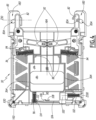
- a locking latch 100 When a locking latch 100 is in the unlocking position, it is moved away from the associated handle 84 by a non-zero distance D100, measured along the latch axis Z100. This position is illustrated in figures 5 And 6 .
- the locking mechanism 80 comprises elastic return members 102, in the example two springs 102.
- each spring 102 exerts an elastic force on a locking latch 100, relative to the housing 32, tending to translate the locking latches in locked position.
- each locking latch comprises a rod 104, which extends along the latch axis Z100 and which comprises a lug 106.
- the lug 106 of a rod 104 is designed to cooperate with a locking notch 108 which is part of the housing 32, so as to block the position of the locking latch 100 along the axis Z100.
- the housing 32 then comprises two locking notches 108, carried by the internal faces of the two cheeks 36.
- a locking latch 100 When a locking latch 100 is in the locking position, it is held in this position under the effect of the force exerted by the spring 102 and, advantageously, by blocking the tip 112 of the rod 104, which is in abuts against a rib 114 of the housing 32, as visible in the Figure 4 .
- Each locking latch 100 is also accessible through an opening 110 made in the housing 32.
- the housing 32 comprises two openings 110, which are, in the example, made in the two cheeks 36.
- the locking latches 100 are intended to be maneuvered from their locking position to their unlocking position by a user, through the openings 110.
- a user can exert force on a locking latch, preferably at the using a tool for safety and normative reasons, such as for example a flat-tipped screwdriver, so as to move the latch along the axis Z100 to its unlocking position, against the elastic force exerted by the spring 102.
- the force exerted by a user is sufficient to slide an inclined surface 106A of the lug 106 against an inclined surface 108A of the locking notch 108.
- the spring 102 is gradually compressed. At the end of this movement, the locking latch is held in the unlocked position by blocking the lug 106 against the locking notch 108.
- This elastic deformation makes it possible to move the lug 106 away from the locking notch 108, that is to say to disengage the lug from the locking notch.
- the lug 106 is not blocked against the locking notch 108, which allows the locking latch 100 to be driven in movement along the axis Z100, under the effect of the spring 102.
- the locking latch is then moved in the direction of the handle 84, until it comes into contact with the handle, which is located, along the latch axis Z100, opposite the latch, i.e. i.e. until the distance D100 is equal to zero.
- the latch is then located between its locking position and its unlocking position, and is held against the handle under the effect of spring 102.
- the handle 84 When the handle 84 is released by the user, it moves in translation to the locking position under the effect of one of the two springs 96, until it no longer prevents the movement of the locking latch 100 towards its locking position, that is to say until it is no longer located opposite the latch, along the latch axis Z100. The locking latch then translates into the locking position, under the effect of spring 102.
- the tab 90 makes it possible to disengage the lug 106 from the locking notch 108, so that the locking latch is automatically returned to the locking position under the effect of the spring 102, even if this return to position locking is only carried out in a second step, after the release of the handle 84.
- the translational movement of the locking latches 100 in the unlocking position is carried out by a user, before actuation of the handles 84 towards their unlocking position, and the translational movement of the latches in the locking position is carried out without intervention of a user, as soon as the handles 84 are released and returned to the locking position.
- the locking mechanism 80 includes a safety bar 120, movable between a locking position, in which the safety bar prevents movement of the handles 84 from their locking position to their unlocking position, and an unlocking position, in which the safety bar does not prevent the movement of the handles and in which all of the circuit breakers 72 are switched to the open configuration, that is to say in which the cutting device 70 is switched to the open configuration.
- the safety bar 120 extends along a longitudinal axis X120 parallel to the axis X30.
- the safety bar 120 is movable in translation, along a bar translation axis Z120 parallel to the perforated faceplate 44 near which the circuit breakers 72 are installed.
- the Z120 bar translation axis is also perpendicular to the width axis X30 of the junction box 30.
- the bar translation axis Z120 is parallel to the height axis Z30 of the box and perpendicular to the handle axis Y84.
- the security bar 120 extends partially outside the housing 32, and can be maneuvered, from outside the housing, by a user between its locking and unlocking positions.
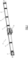
- the safety bar 120 comprises an external part 122, comprising two external wings 124 and a rod 126, each external wing 124 being arranged near a cheek 36 and the rod 126 extending between the external wings over the entire width of the perforated plastron 44, parallel to the width axis X30 and along the longitudinal axis X120.
- the external part 122 advantageously extends outside the housing 32.
- the safety bar 120 also includes two internal wings 128, together forming an internal part of the safety bar, each internal wing being carried by a support 130 of the locking mechanism 80, the support 130 being carried by a cheek. Only one internal wing is visible in the figures, but the position of the other internal wing is deduced from the overall symmetry of the safety bar 120 with respect to a plane perpendicular to the axis X120 and median between the external wings 124.
- each internal wing 128 extends, parallel to the axis Y30, in the extension of an external wing 124 inside the housing 32.
- each support 130 is snapped into a cheek 36.
- the external part 122 extends from the internal part of the safety bar through the window 46 of the perforated faceplate 44.
- the translation of the safety bar 120 between its locking and unlocking positions is guided by the supports 130, on which the internal wings 128 slide and are guided by form cooperation.
- each internal wing 128 comprises a rack 132, which extends parallel to the bar translation axis Z120.
- slots 134 are provided between the internal wings 128 and the external wings 124.
- the rod 126 of the external part 122 comes into contact with these switching levers, which causes them to swing into the open position.
- the rod 126 impacts the switching levers.
- the tilting of the switching levers 74 into the closed position is prevented, by blocking against the rod 126 of the external part 122.
- the cutting device 70 is in open configuration.
- the safety bar 120 therefore makes it possible to switch the cutting device 70 to the open configuration in a simple and rapid manner, by lowering its rod 126 from the high position shown in Figure 7 and on insert a) of the Figure 9 to the lower position shown in figure 8 and on inserts b) and c) of the Figure 9 .
- the locking mechanism 80 comprises a blocking device 140, driven by the safety bar 120.
- the blocking device is designed to block the translation of the handles 84 when the safety bar 120 is in the locking position, and not to block the translation of the handles when the safety bar is in the unlocking position.
- the blocking device 140 comprises two toothed wheels, movable in rotation, relative to the housing 32, around a wheel axis X140 perpendicular to the bar translation axis Z120 and perpendicular to the handle axis Y84.
- a single toothed wheel 140 is shown on the figures 7 And 8 .
- each toothed wheel 140 is associated with a cheek 36 and a handle 84.
- the supports 130 therefore carry the safety bar 120 and the toothed wheels 140, which are assembled together.
- Each toothed wheel 140 comprises, on its periphery surface S140, several teeth 142 engaged with the rack 132 of an internal wing 128 of the safety bar 120.
- a translation of the safety bar around the axis Z120 causes a rotation of the toothed wheels 140 around the axis Z140.
- Each toothed wheel 140 includes two grooves 144, which extend from its peripheral surface S140 towards the wheel axle X140.
- the grooves 144 extend along groove axes X144 radial with respect to the wheel axis X140.
- the two grooves 144 extend along groove axes X144 perpendicular to each other, that is to say separated by an angular sector with an angle equal to 90°.
- the toothed wheel 140 carried by a cheek 36 is aligned, along the axis of width X30, with the pins 88 of the handle 84 associated with this toothed wheel.
- the two grooves 144 extend along groove axes X144 intersecting, but not perpendicular, with the handle axis Y84.
- the handle 84 associated with a toothed wheel is blocked in the locking position, because one of the pins 88 of the handle is in contact with the peripheral surface S140 of the toothed wheel.
- this pawn is the central pawn of the handle. This pin 88 being abutting against the peripheral surface S140, it cannot engage in a groove 144 and the handle is prevented from moving into the unlocking position.
- the other pins 88 of the handle are offset from the toothed wheel.
- offset we mean that the projection of the pins 88 on an axis perpendicular to the handle axis X84 and perpendicular to the wheel axis X140, that is to say, in the example, on a axis parallel to axis Z30, has no intersection with the projection of the toothed wheel on this same axis.
- the two other pins 88 are the peripheral pins and are located on either side of the toothed wheel, along the axis Z30.
- a first groove 144 extends along a groove axis X144 parallel to the handle axis Y84 and a second groove extends along a groove axis perpendicular to the handle axis.
- the handle 84 associated with a toothed wheel can switch from its locking position to its unlocking position, because two of the three pins 88 are offset with the toothed wheel and the third pin 88, corresponding to the pin which is in position. abutting against the peripheral surface S140 when the safety bar 120 is in the locking position, is aligned with the groove 144 extending parallel to the handle axis Y84.
- this pin can engage in this groove 144, and does not prevent the movement of the handle from its locking position to its unlocking position.
- the safety bar 120 is shown in the locked position and the switch levers 74 are shown in the open position.
- the safety bar is shown in the unlocked position. On these two inserts, the safety bar hides the switching levers 74.
- the perforated faceplate 44 engages in the slots 134 provided between the internal wings 128 and the external wings 124 of the safety bar.
- the dismantling of the perforated plastron is impossible, even after removal of the screws 45, because the movement of the faceplate in the plane of the faceplate, denoted P44, is prevented by its contact with the frame of the box 32, more precisely with the crosspieces 34, and with the safety bar 120 , as better visible at figure 2 , and the movement of the faceplate perpendicular to the plane of the faceplate P44, that is to say in a direction away from the box 30, is prevented by the contact of the faceplate with the external wings 124 of the safety bar, at the level of slot 134.
- the plane of the faceplate P44 is parallel to the bar translation axis Z120. Furthermore, in the example, this plane is perpendicular to the depth axis Y30. Thus, in the example, the direction of movement of the box 30 is along the depth axis Y30.
- the projection of the external part 122 of the safety bar that is to say the external wings 124 and the rod 126, in the plane of the faceplate P44, is contained in window 46 of the openwork plastron.
- the perforated plastron 44 does not engage in the slots 134.
- the dismantling of the perforated plastron is made possible by a translation movement of the perforated plastron perpendicular to the plane of the plastron, this that is to say in a direction away from the box 30, parallel to the axis Y30.
- the external part 122 of the safety bar passes inside the window 46.
- the perforated faceplate 44 can only be removed when the safety bar 120 is in the unlocked position.
- the perforated faceplate 44 is particularly simple to dismantle, because its dismantling only requires tilting the safety bar into the unlocking position and removing the screws 45.
- the slots 134 have a height H134, measured in the plane of the faceplate P44 along the bar translation axis Z120, at least equal to 50% of the height H124 of the external wings 124.
- H134 the height of the faceplate P44 along the bar translation axis Z120.
- the height H46 of the window 46 of the perforated faceplate is substantially equal, except for operating clearance, to the height H124 of the external wings 124.
- the height of the external part 122 of the safety bar 120 is substantially equal to the height of the window 46, without being greater.
- the height of the external part 122 of the safety bar 120 is strictly less than the height H46 of the window 46.
- handles 84 can be operated from outside the junction box 30 is particularly advantageous, because this allows the junction box of the busbar 14 to be assembled and dismantled without having to access the inside of the box, i.e. that is to say without having to dismantle one of the faceplates 40, in particular the perforated faceplate 44.
- the safety bar 120 actuation of the handles 84 is only possible when the cutting device 70 is in open configuration, which is particularly advantageous. Indeed, the dismantling of the junction box 30 is thus secure, because it is not possible to dismantle the junction box of the busbar 14 when the electrical circuits connected to it are electrically powered.
- the perforated faceplate 44 is removable only when the safety bar 120 is in the unlocked position is particularly advantageous, because this allows access to the interior of the junction box 30 only when the cutting device is in the open configuration. , which is more secure. In fact, this makes it possible to prevent access to the interior of the box when the electrical connections of the electrical output distribution device 66 are under voltage. Thanks to this system, it is possible to carry out maintenance operations inside the box 30 simply and safely.
- the perforated faceplate 44 is simpler and less expensive to implement than a door, which facilitates the manufacture of the junction box 30 as well as its cost.
- a second embodiment of the junction box 30 is shown in Figure 10 .
- the elements similar to those of the first embodiment bear the same references and operate in the same way.
- the differences between the first and second embodiments are mainly described.
- a component is mentioned in the description of the second embodiment without being shown on the Figure 10 , it corresponds to the same element represented on the figures 1 to 9 for the first embodiment.
- This embodiment can be implemented in the case of a junction box 30 suspended under the busbar 14, with the circuit breakers 72 arranged on one side of the box, and not below the box, which is the case if the junction box is according to the first embodiment.
- the perforated faceplate 44 is perpendicular to the bottom 38.
- the perforated faceplate is parallel to a solid faceplate 42.
- the circuit breakers 72 of the cutting device 70 are then oriented perpendicular to the circuit breakers of the first mode of embodiment, so as to be arranged on the side of the housing comprising the perforated faceplate 44.
- the safety bar is also oriented perpendicular to the safety bar of the first embodiment, so as to extend through the window 46 of the perforated faceplate 44.
- the bar translation axis Z120 is, in this example, parallel to the depth pin Y30 and handle pin Y84.
- the safety bar 120 being assembled with the supports 130 and the toothed wheels 140, these elements are also oriented perpendicular to the supports and the toothed wheels of the first embodiment.
- this change in orientation and positioning of the safety bar 120 and the toothed wheels 140 does not change the operation of the locking mechanism 80, and more particularly, does not change the interaction between the handles 84 and the blocking device 140 formed by the toothed wheels.
- the pins 88 are advantageously positioned on the handles 84, so that in the orientation of the second embodiment, when the safety bar 120 is in the locking position, one of the two peripheral pins can be engage in one of the two grooves 144 of the toothed wheels, and so that, when the safety bar is in the unlocking position, this same peripheral pin abuts against the peripheral surface S140.
- the locking of the handles 84 is thus ensured by the toothed wheels 140 in the same manner as in the first embodiment.
- the groove axis X144 extending parallel to the handle axis Y84 in the configuration of the first embodiment, extends perpendicular to the handle axis Y84 in the configuration of the second embodiment.
- the toothed wheels 140 each include two grooves 144 arranged perpendicularly to each other is particularly advantageous, because this allows that, whatever the orientation of the toothed wheels 140, and therefore of the safety bar 120 and the circuit breakers 72, the One of the two grooves 144 of a wheel is always oriented parallel to the handle axis Y84, when the safety bar is in the locking position. Thanks to this versatility, the circuit breakers 72 and the safety bar 120 can be installed equally on one side of the box parallel, or perpendicular, to the bottom 38, which makes the junction box 30 modular and customizable.
- the handle 84 it is particularly advantageous for the handle 84 to include two peripheral pins 88.
- the junction box comprises two perforated faceplates 44, arranged parallel to each other and perpendicular to the bottom 38, on two opposite sides of the junction box. bypass, and two cutting devices 70 each comprising circuit breakers 72 arranged on both sides of the housing 32 comprising the perforated faceplates 44.
- the locking mechanism then comprises two safety bars 120, each safety bar extending through the window 46 of one of the two perforated faceplates 44 and being able to switch one of the two cutting devices 70, and four toothed wheels 140, each safety bar driving two gears.
- the junction box 30 comprises two safety bars and two pairs of toothed wheels arranged as mirrors of each other.
- the translation of a handle 84 can be blocked by two toothed wheels, because when the two handles are in the locking position, a first peripheral pin 88 of a handle abuts on the peripheral surface S140 of a first gear wheel and a second peripheral pin abuts on the peripheral surface of a second gear wheel.
- the two peripheral pins 88 of a handle engage in two of the grooves 144 of the two toothed wheels associated with this handle.
- the translation of the handles 84 towards their unlocking position is prevented by blocking one of the pins 88 of each handle against the peripheral surface S140 of one of the toothed wheels 140.
- the locking mechanism 80 comprises a different number of hooks 82, for example two or six hooks, which can be arranged on the cheeks 36 or at other locations of the housing 32, so as to allow the fixing of the housing on the set of bars 14.
- the mechanism comprises one hook per cheek 36, or two hooks per cheek 36 and two hooks arranged on the bottom 38.
- the locking mechanism 80 comprises a different number of handles 84, for example a single handle driving all of the hooks 82.
- the junction box 30 is adapted accordingly, for example by providing only a single toothed wheel 140 and a single latch 100.
- the hooks 82 are not carried by the cheeks 36 but, for example, by the bottom 38.
- each handle 84 comprises a different number of pawns 88, for example a single pawn, two pawns or at least four pawns.
- the safety bar 120 is movable in rotation around an axis perpendicular to the handle axis Y84 between its locking position and its position of unlocking, and the racks 132 are replaced by pinions rotating the toothed wheels 140.
- the blocking device 140 comprises a single groove 144, designed to be parallel to the handle axis Y84 when the safety bar 120 is in the unlocking position.
- the blocking device 140 comprises a single toothed wheel 140, allowing the blocking of a single handle 84.
- the safety bar 120 when moved to the unlocked position, switches the circuit breakers 72 to the open configuration without acting on their switching levers 74, for example by operating an opening mechanism internal to the circuit breakers.
- the cutting device 70 comprises a disconnector and the safety bar 120, when moved to the unlocking position, isolates the input electrical connectors 62 from the output electrical distribution device 66 by operating the disconnector.
- the cutting device 70 may not include circuit breakers 72.
Landscapes
- Connection Or Junction Boxes (AREA)
- Patch Boards (AREA)
Claims (9)
- Abzweigkasten (30) für Sammelschiene (14) bestehend aus:- einem Gehäuse (32), bestehend aus:∘ mindestens zwei Querstreben (34);∘ einem Boden (38);∘ zwei Wangen (36), die parallel zueinander und senkrecht zum Boden verlaufen, wobei sich der Boden zwischen den beiden Wangen erstreckt; und∘ mindestens drei Frontplatten (40), die sich senkrecht zu den Wangen erstrecken, wobei mindestens eine Frontplatte eine durchbrochene Frontplatte (44) mit einem Fenster (46) ist,- einem Verriegelungsmechanismus (80), der so konfiguriert ist, dass er die Verriegelung des Gehäuses (32) an einer Sammelschiene (14) ermöglicht, und- einem elektrisches Verteilungssystem (60), bestehend aus:∘ elektrischen Eingangsverbindern (62), die so konfiguriert sind, dass sie elektrisch mit der Sammelschiene verbunden werden, wenn das Gehäuse an der Sammelschiene verriegelt ist;∘ einer Ausgangsstromverteilungsvorrichtung (66), die so konfiguriert ist, dass sie einen nachgeschalteten Stromkreis mit Strom versorgt; und∘ einer Trennvorrichtung (70), die auf einer Seite des Gehäuses angeordnet ist, das eine durchbrochene Frontplatte umfasst und so konfiguriert ist, dass sie umschaltbar ist zwischen:▪ einer geschlossenen Konfiguration, in der die Trennvorrichtung die elektrischen Eingangsverbinder mit der Stromverteilungsvorrichtung verbindet; und▪ einer offenen Konfiguration, in der die Trennvorrichtung die elektrischen Eingangsverbinder von der Stromverteilungsvorrichtung isoliert,die Trennvorrichtung mindestens einen Schalthebel (74) umfasst, der durch das Fenster in der durchbrochenen Frontplatte zugänglich ist und zwischen einer geschlossenen Position, in der sich die Trennvorrichtung in der geschlossenen Konfiguration befindet, und einer offenen Position, in der sich die Trennvorrichtung in der offenen Konfiguration befindet, beweglich ist, wobei der Verriegelungsmechanismus (80) eine Sicherheitsleiste (120) umfasst, die beweglich ist zwischen:- einer Verriegelungsposition, in der die Sicherheitsleiste das Abnehmen der durchbrochenen Frontplatte (44) verhindert; und- einer Entriegelungsposition, in der sich die Trennvorrichtung (70) in der offenen Konfiguration befindet und die Sicherheitsleiste das Abnehmen der durchbrochenen Frontplatte nicht verhindert,dadurch gekennzeichnet, dassdie Querstreben sich zwischen den beiden Wangen erstrecken;die Frontplatten sich zwischen zwei Querstreben erstrecken oder zwischen einer Querstrebe und dem Boden;und wobei die Sicherheitsleiste (120) einen äußeren Teil (122)außerhalb des Gehäuses (32) umfasst, einen inneren Teil (128), der sich in das Innere des Gehäuses erstreckt, vom äußeren Teil durch das Fenster (46) der durchbrochenen Frontplatte (44), und einen Schlitz (134), der zwischen dem inneren Teil und dem äußeren Teil angeordnet ist, und dadurch, dass:- in der Verriegelungsposition der Sicherheitsleiste die Sicherheitsleiste so positioniert ist, dass die durchbrochene Frontplatte in den Schlitz eingreift; und- in der Position, in der die Sicherheitsleiste entriegelt ist, die Sicherheitsleiste so positioniert wird, dass die Frontplatte nicht in den Schlitz eingreift.
- Abzweigkasten (30) nach Anspruch 1, wobei das Kippen der Sicherheitsleiste (120) aus ihrer Verriegelungsstellung in ihre Entriegelungsstellung das Kippen des Schalthebels (74) der Trennvorrichtung (70) aus seiner geschlossenen Stellung in seine geöffnete Stellung bewirkt.
- Abzweigkasten (30) nach einem der vorhergehenden Ansprüche, wobei der Verriegelungsmechanismus (80) unter anderem Folgendes beinhaltet:- mindestens zwei Haken (82), die in Bezug auf das Gehäuse (32) zwischen einer Verriegelungsposition, in der das Gehäuse so konfiguriert ist, dass es an der Sammelschiene verriegelt ist, und einer Entriegelungsposition, in der das Gehäuse so konfiguriert ist, dass es nicht an der Sammelschiene verriegelt ist, beweglich angebracht sind; und- einen Griff (84), der mechanisch mit den Haken verbunden ist und entlang einer Griffachse (Y84) zwischen einer Verriegelungsposition, in der sich die Haken in der Verriegelungsposition befinden, und einer Entriegelungsposition, in der sich die Haken in der Entriegelungsposition befinden, translatorisch beweglich ist,und wobei:- in der Verriegelungsposition die Sicherheitsleiste (120) verhindert, dass sich der Griff aus seiner Verriegelungsposition in seine Entriegelungsposition bewegt; und- in der entriegelten Position die Sicherheitsleiste nicht verhindert, dass sich der Griff bewegt.
- Abzweigkasten (30) nach Anspruch 3, bei dem der innere Teil (128) der Sicherheitsleiste (120) eine Blockiervorrichtung (140) des Griffs (84) antreibt, die so konfiguriert ist, dass in der Verriegelungsposition der Sicherheitsleiste die
Translation des Griffs entlang der Griffachse (Y84) verhindert wird, und damit in der Entriegelungsposition der Sicherheitsleiste die Translation des Griffs entlang der Griffachse (Y84) nicht verhindert wird. - Abzweigkasten (30) nach einem der vorhergehenden Ansprüche, wobei in der Entriegelungsposition der Sicherheitsleiste (120) die Sicherheitsleiste so positioniert ist, dass die Projektion der Hülle seines äußeren Teils (122) in einer Ebene (P44) der durchbrochenen Frontplatte (44) in dem Fenster (46) der durchbrochenen Frontplatte (44) enthalten ist.
- Abzweigkasten (30) nach einem der vorhergehenden Ansprüche, wobei eine Höhe (H124) des äußeren Teils (122) der Sicherheitsleiste (120), gemessen in einer Ebene (P44) der durchbrochenen Frontplatte (44), kleiner oder gleich einer Höhe (H46) des Fensters (46) der durchbrochenen Frontplatte, gemessen in der Ebene der Frontplatte, ist.
- Abzweigkasten (30) nach einem der vorhergehenden Ansprüche, wobei eine Höhe (H134) der Latenz (134) der Sicherheitsleiste (120), gemessen in einer Ebene (P44) der durchbrochenen Frontplatte (44), mindestens 50 % einer Höhe (H124) des äußeren Teils (122), gemessen in der Ebene der Frontplatte, beträgt.
- Abzweigkasten (30) nach einem der vorhergehenden Ansprüche, der außerdem zwei Halterungen (130) umfasst, wobei jede Halterung von einer Wange (36) getragen wird, und wobei:- die Sicherheitsleiste (120) zwischen ihrer verriegelten und ihrer entriegelten Position translatorisch beweglich ist;- der äußere Teil (122) der Sicherheitsleiste zwei äußere Flügel (124) und einen Schaft (126) umfasst, der sich zwischen den beiden äußeren Flügeln erstreckt, wobei jeder äußere Flügel in der Nähe einer Wange angeordnet ist;- der innere Teil (128) der Sicherheitsleiste zwei innere Flügel (128) umfasst, wobei sich jeder innere Flügel in Verlängerung eines äußeren Flügels innerhalb des Gehäuses (32) erstreckt und so konfiguriert ist, dass er auf den Stützen gleitet, um die Sicherheitsleiste in Translation zu führen; und- die Sicherheitsleiste zwei Schlitze (134) umfasst, die zwischen den äußeren und den inneren Flügeln angeordnet sind.
- Abzweigkasten (30) nach einem der vorhergehenden Ansprüche, wobei das Gehäuse (32) insgesamt kubisch geformt ist, und wobei die durchbrochene Frontplatte (44) entweder parallel oder senkrecht zum Boden (38) des Gehäuses verläuft.
Applications Claiming Priority (1)
| Application Number | Priority Date | Filing Date | Title |
|---|---|---|---|
| FR2106263A FR3124032B1 (fr) | 2021-06-14 | 2021-06-14 | Coffret de dérivation pour jeu de barres |
Publications (2)
| Publication Number | Publication Date |
|---|---|
| EP4106121A1 EP4106121A1 (de) | 2022-12-21 |
| EP4106121B1 true EP4106121B1 (de) | 2024-01-24 |
Family
ID=77999048
Family Applications (1)
| Application Number | Title | Priority Date | Filing Date |
|---|---|---|---|
| EP22178611.4A Active EP4106121B1 (de) | 2021-06-14 | 2022-06-13 | Abzweigkasten für sammelschienen |
Country Status (3)
| Country | Link |
|---|---|
| EP (1) | EP4106121B1 (de) |
| CN (1) | CN115483577A (de) |
| FR (1) | FR3124032B1 (de) |
Family Cites Families (3)
| Publication number | Priority date | Publication date | Assignee | Title |
|---|---|---|---|---|
| US3301989A (en) * | 1965-07-02 | 1967-01-31 | Gen Electric | Handle assembly for circuit breakers |
| CN110752567B (zh) * | 2019-10-29 | 2021-09-21 | 威腾电气集团股份有限公司 | 具有三重联锁功能的插接箱 |
| CN112420419B (zh) * | 2020-11-09 | 2023-05-12 | 威腾电气集团股份有限公司 | 一种具有联动锁定功能的插接箱 |
-
2021
- 2021-06-14 FR FR2106263A patent/FR3124032B1/fr not_active Expired - Fee Related
-
2022
- 2022-06-13 EP EP22178611.4A patent/EP4106121B1/de active Active
- 2022-06-14 CN CN202210668352.9A patent/CN115483577A/zh active Pending
Also Published As
| Publication number | Publication date |
|---|---|
| FR3124032B1 (fr) | 2024-01-05 |
| FR3124032A1 (fr) | 2022-12-16 |
| CN115483577A (zh) | 2022-12-16 |
| EP4106121A1 (de) | 2022-12-21 |
Similar Documents
| Publication | Publication Date | Title |
|---|---|---|
| EP0407241B1 (de) | Lösbare Platine zur Halterung von elektrischen Geräten für eine Leistungsverteilereinrichtung | |
| EP0869594B1 (de) | Motoransteuerbaugruppe | |
| EP2930803B1 (de) | Einheit zum positionieren der einschübe für eine schaltanlage, eine solche einheit umfassende schaltanlage und montageverfahren dieser einheit | |
| EP0186556B1 (de) | Verteilersystem und -säule für elektrische Schaltanlagen | |
| EP0748013A1 (de) | Vorrichtung zur elektrischen Verbindung von modularen Geräten wie Schaltern oder dergleichen | |
| EP1885036B1 (de) | Verteilereinheit für elektrische Anlage | |
| EP4106121B1 (de) | Abzweigkasten für sammelschienen | |
| EP4106120B1 (de) | Abzweigkasten für sammelschienen | |
| EP4106122B1 (de) | Abzweigkasten für sammelschienen | |
| EP3703091A1 (de) | Elektrische schaltvorrichtung für schienenfahrzeug, und mit dieser vorrichtung ausgestattetes schienenfahrzeug | |
| FR2653607A1 (fr) | Dispositif pour la realisation d'ensembles pour la commande et la protection de circuits electriques basse tension. | |
| FR2646568A1 (en) | Electrical distribution panel equipped with isolators | |
| FR2649546A1 (fr) | Protection de couplage sequentiel pour connecteur a fiches | |
| EP3651277A1 (de) | Steckdose | |
| EP0233420B1 (de) | Trennbare Stromentnahmevorrichtung auf einer Verteilsäule mit Sammelschiene | |
| EP2117028B1 (de) | Modulare elektrische Einrichtung | |
| EP1655806B1 (de) | Verbinder, Sammelschienenadapter mit Verbinder und Verteilergehäuse mit Sammelschienenadapter und Verbinder | |
| FR2708392A1 (fr) | Cellule moyenne tension sous enveloppe métallique avec disjoncteur auto-sectionneur. | |
| EP3255732B1 (de) | Elektrische verbindungsklemme, die einen verbindungshebel umfasst, und entsprechende elektrische geräte | |
| FR3020506A1 (fr) | Borne de connexion electrique multi-conducteurs | |
| CH716357B1 (fr) | Appareil modulaire électrique muni d'un élément de blocage. | |
| FR2960697A1 (fr) | Chassis de montage pour appareils electriques | |
| EP4277044A1 (de) | Verbindungsvorrichtung und elektrische schalttafel mit einer solchen vorrichtung | |
| EP2535990B1 (de) | Elektrogerät zum Befestigen durch Einrasten auf einer waagrechten Halterungsschiene | |
| EP1011179A1 (de) | Aus einem oder mehreren Geräten bestehende elektronische Apparatur, mit Eingangs-/Ausgangsanschlüssen auf demselben Verbindungsvorderteil |
Legal Events
| Date | Code | Title | Description |
|---|---|---|---|
| PUAI | Public reference made under article 153(3) epc to a published international application that has entered the european phase |
Free format text: ORIGINAL CODE: 0009012 |
|
| STAA | Information on the status of an ep patent application or granted ep patent |
Free format text: STATUS: THE APPLICATION HAS BEEN PUBLISHED |
|
| AK | Designated contracting states |
Kind code of ref document: A1 Designated state(s): AL AT BE BG CH CY CZ DE DK EE ES FI FR GB GR HR HU IE IS IT LI LT LU LV MC MK MT NL NO PL PT RO RS SE SI SK SM TR |
|
| STAA | Information on the status of an ep patent application or granted ep patent |
Free format text: STATUS: REQUEST FOR EXAMINATION WAS MADE |
|
| 17P | Request for examination filed |
Effective date: 20230526 |
|
| RBV | Designated contracting states (corrected) |
Designated state(s): AL AT BE BG CH CY CZ DE DK EE ES FI FR GB GR HR HU IE IS IT LI LT LU LV MC MK MT NL NO PL PT RO RS SE SI SK SM TR |
|
| GRAP | Despatch of communication of intention to grant a patent |
Free format text: ORIGINAL CODE: EPIDOSNIGR1 |
|
| STAA | Information on the status of an ep patent application or granted ep patent |
Free format text: STATUS: GRANT OF PATENT IS INTENDED |
|
| INTG | Intention to grant announced |
Effective date: 20231013 |
|
| GRAS | Grant fee paid |
Free format text: ORIGINAL CODE: EPIDOSNIGR3 |
|
| GRAA | (expected) grant |
Free format text: ORIGINAL CODE: 0009210 |
|
| STAA | Information on the status of an ep patent application or granted ep patent |
Free format text: STATUS: THE PATENT HAS BEEN GRANTED |
|
| AK | Designated contracting states |
Kind code of ref document: B1 Designated state(s): AL AT BE BG CH CY CZ DE DK EE ES FI FR GB GR HR HU IE IS IT LI LT LU LV MC MK MT NL NO PL PT RO RS SE SI SK SM TR |
|
| REG | Reference to a national code |
Ref country code: GB Ref legal event code: FG4D Free format text: NOT ENGLISH |
|
| REG | Reference to a national code |
Ref country code: CH Ref legal event code: EP |
|
| REG | Reference to a national code |
Ref country code: IE Ref legal event code: FG4D Free format text: LANGUAGE OF EP DOCUMENT: FRENCH |
|
| REG | Reference to a national code |
Ref country code: DE Ref legal event code: R096 Ref document number: 602022001671 Country of ref document: DE |
|
| REG | Reference to a national code |
Ref country code: LT Ref legal event code: MG9D |
|
| REG | Reference to a national code |
Ref country code: NL Ref legal event code: MP Effective date: 20240124 |
|
| PG25 | Lapsed in a contracting state [announced via postgrant information from national office to epo] |
Ref country code: NL Free format text: LAPSE BECAUSE OF FAILURE TO SUBMIT A TRANSLATION OF THE DESCRIPTION OR TO PAY THE FEE WITHIN THE PRESCRIBED TIME-LIMIT Effective date: 20240124 |
|
| PG25 | Lapsed in a contracting state [announced via postgrant information from national office to epo] |
Ref country code: NL Free format text: LAPSE BECAUSE OF FAILURE TO SUBMIT A TRANSLATION OF THE DESCRIPTION OR TO PAY THE FEE WITHIN THE PRESCRIBED TIME-LIMIT Effective date: 20240124 |
|
| PG25 | Lapsed in a contracting state [announced via postgrant information from national office to epo] |
Ref country code: IS Free format text: LAPSE BECAUSE OF FAILURE TO SUBMIT A TRANSLATION OF THE DESCRIPTION OR TO PAY THE FEE WITHIN THE PRESCRIBED TIME-LIMIT Effective date: 20240524 |
|
| PG25 | Lapsed in a contracting state [announced via postgrant information from national office to epo] |
Ref country code: LT Free format text: LAPSE BECAUSE OF FAILURE TO SUBMIT A TRANSLATION OF THE DESCRIPTION OR TO PAY THE FEE WITHIN THE PRESCRIBED TIME-LIMIT Effective date: 20240124 |
|
| PG25 | Lapsed in a contracting state [announced via postgrant information from national office to epo] |
Ref country code: GR Free format text: LAPSE BECAUSE OF FAILURE TO SUBMIT A TRANSLATION OF THE DESCRIPTION OR TO PAY THE FEE WITHIN THE PRESCRIBED TIME-LIMIT Effective date: 20240425 |
|
| REG | Reference to a national code |
Ref country code: AT Ref legal event code: MK05 Ref document number: 1652930 Country of ref document: AT Kind code of ref document: T Effective date: 20240124 |
|
| PG25 | Lapsed in a contracting state [announced via postgrant information from national office to epo] |
Ref country code: RS Free format text: LAPSE BECAUSE OF FAILURE TO SUBMIT A TRANSLATION OF THE DESCRIPTION OR TO PAY THE FEE WITHIN THE PRESCRIBED TIME-LIMIT Effective date: 20240424 Ref country code: HR Free format text: LAPSE BECAUSE OF FAILURE TO SUBMIT A TRANSLATION OF THE DESCRIPTION OR TO PAY THE FEE WITHIN THE PRESCRIBED TIME-LIMIT Effective date: 20240124 |
|
| PG25 | Lapsed in a contracting state [announced via postgrant information from national office to epo] |
Ref country code: ES Free format text: LAPSE BECAUSE OF FAILURE TO SUBMIT A TRANSLATION OF THE DESCRIPTION OR TO PAY THE FEE WITHIN THE PRESCRIBED TIME-LIMIT Effective date: 20240124 |
|
| PG25 | Lapsed in a contracting state [announced via postgrant information from national office to epo] |
Ref country code: AT Free format text: LAPSE BECAUSE OF FAILURE TO SUBMIT A TRANSLATION OF THE DESCRIPTION OR TO PAY THE FEE WITHIN THE PRESCRIBED TIME-LIMIT Effective date: 20240124 |
|
| PG25 | Lapsed in a contracting state [announced via postgrant information from national office to epo] |
Ref country code: RS Free format text: LAPSE BECAUSE OF FAILURE TO SUBMIT A TRANSLATION OF THE DESCRIPTION OR TO PAY THE FEE WITHIN THE PRESCRIBED TIME-LIMIT Effective date: 20240424 Ref country code: NO Free format text: LAPSE BECAUSE OF FAILURE TO SUBMIT A TRANSLATION OF THE DESCRIPTION OR TO PAY THE FEE WITHIN THE PRESCRIBED TIME-LIMIT Effective date: 20240424 Ref country code: LT Free format text: LAPSE BECAUSE OF FAILURE TO SUBMIT A TRANSLATION OF THE DESCRIPTION OR TO PAY THE FEE WITHIN THE PRESCRIBED TIME-LIMIT Effective date: 20240124 Ref country code: IS Free format text: LAPSE BECAUSE OF FAILURE TO SUBMIT A TRANSLATION OF THE DESCRIPTION OR TO PAY THE FEE WITHIN THE PRESCRIBED TIME-LIMIT Effective date: 20240524 Ref country code: HR Free format text: LAPSE BECAUSE OF FAILURE TO SUBMIT A TRANSLATION OF THE DESCRIPTION OR TO PAY THE FEE WITHIN THE PRESCRIBED TIME-LIMIT Effective date: 20240124 Ref country code: GR Free format text: LAPSE BECAUSE OF FAILURE TO SUBMIT A TRANSLATION OF THE DESCRIPTION OR TO PAY THE FEE WITHIN THE PRESCRIBED TIME-LIMIT Effective date: 20240425 Ref country code: FI Free format text: LAPSE BECAUSE OF FAILURE TO SUBMIT A TRANSLATION OF THE DESCRIPTION OR TO PAY THE FEE WITHIN THE PRESCRIBED TIME-LIMIT Effective date: 20240124 Ref country code: ES Free format text: LAPSE BECAUSE OF FAILURE TO SUBMIT A TRANSLATION OF THE DESCRIPTION OR TO PAY THE FEE WITHIN THE PRESCRIBED TIME-LIMIT Effective date: 20240124 Ref country code: BG Free format text: LAPSE BECAUSE OF FAILURE TO SUBMIT A TRANSLATION OF THE DESCRIPTION OR TO PAY THE FEE WITHIN THE PRESCRIBED TIME-LIMIT Effective date: 20240124 Ref country code: AT Free format text: LAPSE BECAUSE OF FAILURE TO SUBMIT A TRANSLATION OF THE DESCRIPTION OR TO PAY THE FEE WITHIN THE PRESCRIBED TIME-LIMIT Effective date: 20240124 |
|
| PG25 | Lapsed in a contracting state [announced via postgrant information from national office to epo] |
Ref country code: PT Free format text: LAPSE BECAUSE OF FAILURE TO SUBMIT A TRANSLATION OF THE DESCRIPTION OR TO PAY THE FEE WITHIN THE PRESCRIBED TIME-LIMIT Effective date: 20240524 Ref country code: PL Free format text: LAPSE BECAUSE OF FAILURE TO SUBMIT A TRANSLATION OF THE DESCRIPTION OR TO PAY THE FEE WITHIN THE PRESCRIBED TIME-LIMIT Effective date: 20240124 |
|
| PG25 | Lapsed in a contracting state [announced via postgrant information from national office to epo] |
Ref country code: SE Free format text: LAPSE BECAUSE OF FAILURE TO SUBMIT A TRANSLATION OF THE DESCRIPTION OR TO PAY THE FEE WITHIN THE PRESCRIBED TIME-LIMIT Effective date: 20240124 Ref country code: PT Free format text: LAPSE BECAUSE OF FAILURE TO SUBMIT A TRANSLATION OF THE DESCRIPTION OR TO PAY THE FEE WITHIN THE PRESCRIBED TIME-LIMIT Effective date: 20240524 Ref country code: PL Free format text: LAPSE BECAUSE OF FAILURE TO SUBMIT A TRANSLATION OF THE DESCRIPTION OR TO PAY THE FEE WITHIN THE PRESCRIBED TIME-LIMIT Effective date: 20240124 Ref country code: LV Free format text: LAPSE BECAUSE OF FAILURE TO SUBMIT A TRANSLATION OF THE DESCRIPTION OR TO PAY THE FEE WITHIN THE PRESCRIBED TIME-LIMIT Effective date: 20240124 |
|
| PG25 | Lapsed in a contracting state [announced via postgrant information from national office to epo] |
Ref country code: DK Free format text: LAPSE BECAUSE OF FAILURE TO SUBMIT A TRANSLATION OF THE DESCRIPTION OR TO PAY THE FEE WITHIN THE PRESCRIBED TIME-LIMIT Effective date: 20240124 |
|
| PG25 | Lapsed in a contracting state [announced via postgrant information from national office to epo] |
Ref country code: SM Free format text: LAPSE BECAUSE OF FAILURE TO SUBMIT A TRANSLATION OF THE DESCRIPTION OR TO PAY THE FEE WITHIN THE PRESCRIBED TIME-LIMIT Effective date: 20240124 |
|
| PG25 | Lapsed in a contracting state [announced via postgrant information from national office to epo] |
Ref country code: EE Free format text: LAPSE BECAUSE OF FAILURE TO SUBMIT A TRANSLATION OF THE DESCRIPTION OR TO PAY THE FEE WITHIN THE PRESCRIBED TIME-LIMIT Effective date: 20240124 Ref country code: CZ Free format text: LAPSE BECAUSE OF FAILURE TO SUBMIT A TRANSLATION OF THE DESCRIPTION OR TO PAY THE FEE WITHIN THE PRESCRIBED TIME-LIMIT Effective date: 20240124 |
|
| REG | Reference to a national code |
Ref country code: DE Ref legal event code: R097 Ref document number: 602022001671 Country of ref document: DE |
|
| PG25 | Lapsed in a contracting state [announced via postgrant information from national office to epo] |
Ref country code: SK Free format text: LAPSE BECAUSE OF FAILURE TO SUBMIT A TRANSLATION OF THE DESCRIPTION OR TO PAY THE FEE WITHIN THE PRESCRIBED TIME-LIMIT Effective date: 20240124 |
|
| PG25 | Lapsed in a contracting state [announced via postgrant information from national office to epo] |
Ref country code: SM Free format text: LAPSE BECAUSE OF FAILURE TO SUBMIT A TRANSLATION OF THE DESCRIPTION OR TO PAY THE FEE WITHIN THE PRESCRIBED TIME-LIMIT Effective date: 20240124 Ref country code: SK Free format text: LAPSE BECAUSE OF FAILURE TO SUBMIT A TRANSLATION OF THE DESCRIPTION OR TO PAY THE FEE WITHIN THE PRESCRIBED TIME-LIMIT Effective date: 20240124 Ref country code: EE Free format text: LAPSE BECAUSE OF FAILURE TO SUBMIT A TRANSLATION OF THE DESCRIPTION OR TO PAY THE FEE WITHIN THE PRESCRIBED TIME-LIMIT Effective date: 20240124 Ref country code: DK Free format text: LAPSE BECAUSE OF FAILURE TO SUBMIT A TRANSLATION OF THE DESCRIPTION OR TO PAY THE FEE WITHIN THE PRESCRIBED TIME-LIMIT Effective date: 20240124 Ref country code: CZ Free format text: LAPSE BECAUSE OF FAILURE TO SUBMIT A TRANSLATION OF THE DESCRIPTION OR TO PAY THE FEE WITHIN THE PRESCRIBED TIME-LIMIT Effective date: 20240124 |
|
| PLBE | No opposition filed within time limit |
Free format text: ORIGINAL CODE: 0009261 |
|
| STAA | Information on the status of an ep patent application or granted ep patent |
Free format text: STATUS: NO OPPOSITION FILED WITHIN TIME LIMIT |
|
| PG25 | Lapsed in a contracting state [announced via postgrant information from national office to epo] |
Ref country code: IT Free format text: LAPSE BECAUSE OF FAILURE TO SUBMIT A TRANSLATION OF THE DESCRIPTION OR TO PAY THE FEE WITHIN THE PRESCRIBED TIME-LIMIT Effective date: 20240124 |
|
| PG25 | Lapsed in a contracting state [announced via postgrant information from national office to epo] |
Ref country code: IT Free format text: LAPSE BECAUSE OF FAILURE TO SUBMIT A TRANSLATION OF THE DESCRIPTION OR TO PAY THE FEE WITHIN THE PRESCRIBED TIME-LIMIT Effective date: 20240124 |
|
| 26N | No opposition filed |
Effective date: 20241025 |
|
| PG25 | Lapsed in a contracting state [announced via postgrant information from national office to epo] |
Ref country code: MC Free format text: LAPSE BECAUSE OF FAILURE TO SUBMIT A TRANSLATION OF THE DESCRIPTION OR TO PAY THE FEE WITHIN THE PRESCRIBED TIME-LIMIT Effective date: 20240124 |
|
| PG25 | Lapsed in a contracting state [announced via postgrant information from national office to epo] |
Ref country code: LU Free format text: LAPSE BECAUSE OF NON-PAYMENT OF DUE FEES Effective date: 20240613 |
|
| PG25 | Lapsed in a contracting state [announced via postgrant information from national office to epo] |
Ref country code: IE Free format text: LAPSE BECAUSE OF NON-PAYMENT OF DUE FEES Effective date: 20240613 |
|
| PG25 | Lapsed in a contracting state [announced via postgrant information from national office to epo] |
Ref country code: SI Free format text: LAPSE BECAUSE OF FAILURE TO SUBMIT A TRANSLATION OF THE DESCRIPTION OR TO PAY THE FEE WITHIN THE PRESCRIBED TIME-LIMIT Effective date: 20240124 Ref country code: BE Free format text: LAPSE BECAUSE OF NON-PAYMENT OF DUE FEES Effective date: 20240630 |
|
| REG | Reference to a national code |
Ref country code: BE Ref legal event code: MM Effective date: 20240630 |
|
| PGFP | Annual fee paid to national office [announced via postgrant information from national office to epo] |
Ref country code: DE Payment date: 20250626 Year of fee payment: 4 |
|
| PGFP | Annual fee paid to national office [announced via postgrant information from national office to epo] |
Ref country code: FR Payment date: 20250624 Year of fee payment: 4 |
|
| PG25 | Lapsed in a contracting state [announced via postgrant information from national office to epo] |
Ref country code: RO Free format text: LAPSE BECAUSE OF FAILURE TO SUBMIT A TRANSLATION OF THE DESCRIPTION OR TO PAY THE FEE WITHIN THE PRESCRIBED TIME-LIMIT Effective date: 20240124 |
|
| PG25 | Lapsed in a contracting state [announced via postgrant information from national office to epo] |
Ref country code: CY Free format text: LAPSE BECAUSE OF FAILURE TO SUBMIT A TRANSLATION OF THE DESCRIPTION OR TO PAY THE FEE WITHIN THE PRESCRIBED TIME-LIMIT; INVALID AB INITIO Effective date: 20220613 |
|
| REG | Reference to a national code |
Ref country code: CH Ref legal event code: H13 Free format text: ST27 STATUS EVENT CODE: U-0-0-H10-H13 (AS PROVIDED BY THE NATIONAL OFFICE) Effective date: 20260127 |
|
| PG25 | Lapsed in a contracting state [announced via postgrant information from national office to epo] |
Ref country code: HU Free format text: LAPSE BECAUSE OF FAILURE TO SUBMIT A TRANSLATION OF THE DESCRIPTION OR TO PAY THE FEE WITHIN THE PRESCRIBED TIME-LIMIT; INVALID AB INITIO Effective date: 20220613 |
|
| PG25 | Lapsed in a contracting state [announced via postgrant information from national office to epo] |
Ref country code: CH Free format text: LAPSE BECAUSE OF NON-PAYMENT OF DUE FEES Effective date: 20250630 |