EP4106122B1 - Abzweigkasten für sammelschienen - Google Patents
Abzweigkasten für sammelschienen Download PDFInfo
- Publication number
- EP4106122B1 EP4106122B1 EP22178628.8A EP22178628A EP4106122B1 EP 4106122 B1 EP4106122 B1 EP 4106122B1 EP 22178628 A EP22178628 A EP 22178628A EP 4106122 B1 EP4106122 B1 EP 4106122B1
- Authority
- EP
- European Patent Office
- Prior art keywords
- faceplate
- box
- flanges
- housing
- tap
- Prior art date
- Legal status (The legal status is an assumption and is not a legal conclusion. Google has not performed a legal analysis and makes no representation as to the accuracy of the status listed.)
- Active
Links
Images







Classifications
-
- H—ELECTRICITY
- H02—GENERATION; CONVERSION OR DISTRIBUTION OF ELECTRIC POWER
- H02B—BOARDS, SUBSTATIONS OR SWITCHING ARRANGEMENTS FOR THE SUPPLY OR DISTRIBUTION OF ELECTRIC POWER
- H02B1/00—Frameworks, boards, panels, desks, casings; Details of substations or switching arrangements
- H02B1/20—Bus-bar or other wiring layouts, e.g. in cubicles, in switchyards
-
- H—ELECTRICITY
- H02—GENERATION; CONVERSION OR DISTRIBUTION OF ELECTRIC POWER
- H02G—INSTALLATION OF ELECTRIC CABLES OR LINES, OR OF COMBINED OPTICAL AND ELECTRIC CABLES OR LINES
- H02G5/00—Installations of bus-bars
- H02G5/06—Totally-enclosed installations, e.g. in metal casings
- H02G5/08—Connection boxes therefor
-
- H—ELECTRICITY
- H01—ELECTRIC ELEMENTS
- H01H—ELECTRIC SWITCHES; RELAYS; SELECTORS; EMERGENCY PROTECTIVE DEVICES
- H01H71/00—Details of the protective switches or relays covered by groups H01H73/00 - H01H83/00
- H01H71/08—Terminals; Connections
-
- H—ELECTRICITY
- H02—GENERATION; CONVERSION OR DISTRIBUTION OF ELECTRIC POWER
- H02B—BOARDS, SUBSTATIONS OR SWITCHING ARRANGEMENTS FOR THE SUPPLY OR DISTRIBUTION OF ELECTRIC POWER
- H02B1/00—Frameworks, boards, panels, desks, casings; Details of substations or switching arrangements
- H02B1/015—Boards, panels, desks; Parts thereof or accessories therefor
- H02B1/04—Mounting thereon of switches or of other devices in general, the switch or device having, or being without, casing
-
- H—ELECTRICITY
- H02—GENERATION; CONVERSION OR DISTRIBUTION OF ELECTRIC POWER
- H02B—BOARDS, SUBSTATIONS OR SWITCHING ARRANGEMENTS FOR THE SUPPLY OR DISTRIBUTION OF ELECTRIC POWER
- H02B1/00—Frameworks, boards, panels, desks, casings; Details of substations or switching arrangements
- H02B1/24—Circuit arrangements for boards or switchyards
-
- H—ELECTRICITY
- H02—GENERATION; CONVERSION OR DISTRIBUTION OF ELECTRIC POWER
- H02B—BOARDS, SUBSTATIONS OR SWITCHING ARRANGEMENTS FOR THE SUPPLY OR DISTRIBUTION OF ELECTRIC POWER
- H02B1/00—Frameworks, boards, panels, desks, casings; Details of substations or switching arrangements
- H02B1/26—Casings; Parts thereof or accessories therefor
- H02B1/46—Boxes; Parts thereof or accessories therefor
-
- H—ELECTRICITY
- H02—GENERATION; CONVERSION OR DISTRIBUTION OF ELECTRIC POWER
- H02B—BOARDS, SUBSTATIONS OR SWITCHING ARRANGEMENTS FOR THE SUPPLY OR DISTRIBUTION OF ELECTRIC POWER
- H02B1/00—Frameworks, boards, panels, desks, casings; Details of substations or switching arrangements
- H02B1/26—Casings; Parts thereof or accessories therefor
- H02B1/46—Boxes; Parts thereof or accessories therefor
- H02B1/48—Mounting of devices therein
Definitions
- the present invention relates to a busbar junction box.
- busbars In the field of industrial electrical distribution, it is known to use busbars in an electrical installation to distribute electrical energy from an electricity source to electrical circuits. It is known to install such busbars in trunking, more commonly called "ducts".
- junction box on a busbar, to allow the connection of an electrical circuit to the busbar.
- a junction box generally comprises connectors, electrically connected to the busbar, an electrical distribution device, allowing an electrical circuit to be supplied, and a cut-off device, allowing either to connect together, or to isolate, the connectors and the distribution device.
- the electrical distribution device as well as the cut-off device are arranged on the sides of the box, so as to be accessible from outside the box.
- junction box is adapted to an electrical installation during its manufacture, to take into account the constraints specific to the electrical installation.
- the dimensions of the box are chosen before its manufacture, as are the positioning of the electrical distribution device and the cut-off device.
- Each junction box is therefore custom-made, which is expensive.
- junction boxes are not versatile, because they cannot be modified, or customized, at the time of their implementation within the electrical installation. However, it may happen, at the time of implementation of a junction box, to find that its configuration is not adapted to the electrical installation. It is then often necessary to have to change certain parts of the box to modify it, or even to have to change the entire box, which is expensive and leads to significant loss of time.
- the document CN-A-110752567 describes a junction box comprising a rear wall, two side walls, two cheeks and a door attached to one of the side walls by a hinge.
- a circuit breaker can be operated through a window in the door.
- This junction box is not versatile, as the position of the door and the circuit breaker cannot be changed.
- each opening of the junction box can accommodate several separate faceplates from a faceplate assembly, which makes the configuration of the box easy to modify.
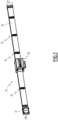
- An electrical installation 10 is shown in the Figure 1 .
- This electrical installation comprises an electricity source 12 and a busbar 14, connected to the electricity source 12.
- the busbar comprises in practice several conductive bars, for example made of copper or aluminum.
- the busbar comprises five conductive bars, one of which is connected to a neutral of the electricity source, three are connected to phases of the electricity source and one is connected to earth.
- the electricity source 12 is a source delivering a three-phase current and a neutral.
- the conductive bar connected to earth is not visible at the Figure 1 .
- the busbar 14 makes it possible to distribute electrical power delivered by the electricity source 12 to electrical circuits connected to it.
- several groups of connectors 16 are connected to the busbar 14.
- the electrical installation 10 comprises six groups of connectors 16.
- the number of groups of connectors 16 varies depending on the length of the busbar 14 and the number of electrical circuits to be connected to the busbar.
- each group of connectors comprises five electrical connectors.
- the busbar 14 is protected inside an electrical trunking 18, in other words in a “duct”.
- this electrical trunking is made of polymer material.
- the electrical trunking is electrically insulating.
- the electrical trunking 18 also carries the groups of connectors 16.
- the busbar 14 and the electrical trunking 18 extend along a longitudinal axis X14.
- the longitudinal axis X14 is horizontal. In practice, depending on the specificities of the electrical installation 10, the longitudinal axis X14 is horizontal, vertical, or of any other orientation.
- the electricity source 12 is fixed to a first end of the busbar 14 and the electrical trunking 18, along the axis X14. At the opposite end of the electrical trunking, the end of the busbar is visible, which allows a second busbar and a second electrical trunking to be connected thereto, so as to extend the electrical installation 10. When such an extension is not necessary, a cover is then installed on the opposite end of the electrical trunking, to mask the end of the busbar.
- the electrical installation 10 also includes a branch box 30, fixed to the electrical trunking 18 and making it possible to connect the busbar 14 to an electrical circuit not shown, in order to supply this electrical circuit.
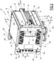
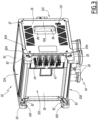
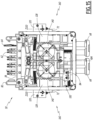
- the 30 junction box comprises a housing 32.
- the housing 32 has generally the shape of a rectangular parallelepiped, and preferably generally a cubic shape. Thus, the housing 32 has six sides.
- X30 a width axis
- Y30 a depth axis
- Z30 a height axis of the junction box.
- the housing 32 comprises two crosspieces 34 which extend parallel to the axis X30 and a bottom 38 which extends parallel to the crosspieces 34 and which together form a frame of the housing.
- the width axis X30 of the box is parallel to the longitudinal axis X14 of the busbar set 14.
- the housing 32 comprises two cheeks 36, parallel to each other.
- the cheeks 36 are flat and generally rectangular, and advantageously generally square, with cutouts.
- the crosspieces 34 extend between the two cheeks 36 and are advantageously arranged at two adjacent corners of the cheeks.
- the bottom 38 extends between the two cheeks 36, advantageously between two adjacent corners of the cheeks, opposite the crosspieces 34.
- the cheeks 36 close two of the six sides of the housing 32.
- the cheeks 36 are located on either side of the housing 32, along the width axis X30.
- the four sides of the housing 32 not being closed by the cheeks 36 are denoted 32A, 32B, 32C and 32D and correspond respectively to the upper, lower, front and rear side of the housing 32, according to the orientation of the figures 2 And 3 .
- the bottom 38 extending between the cheeks 36, it closes one of the sides 32A, 32B, 32C and 32D of the housing 32.
- the bottom 38 is parallel with the electrical trunking, and preferably in contact with the electrical trunking.
- the bottom 38 completely closes the rear side 32D of the case.
- the housing 32 comprises four crosspieces 34 which extend between the cheeks 36 while being arranged at the four corners of the cheeks.
- the bottom 38 extends between two adjacent crosspieces 34, so as to close one of the sides 32A, 32B, 32C and 32D of the housing.
- the bottom 38 and the two cheeks 36 therefore close three of the six sides of the housing 32.
- the housing 32 thus comprises three openings 39, each opening 39 corresponding to one side of the housing 32 extending perpendicular to the cheeks between two crosspieces 34 or between a crosspiece and the bottom 38.
- the housing 32 comprises three faceplates 40, rectangular in shape, and perpendicular to the cheeks 36.
- the three faceplates 40 two are parallel to each other and perpendicular to the bottom 38, and one is parallel to the bottom 38.
- Each faceplate 40 extends between two crosspieces 34 or between a crosspiece and the bottom.
- the three faceplates 40 close three of the six sides of the housing 32.
- the cheeks 36 and the faceplates 40 are thus fixed to the frame of the housing 32, that is to say to the crosspieces 34 and to the bottom 38.
- the housing 32 is closed, that is to say that the interior of the housing is not accessible.
- two of the three faceplates 40 are solid faceplates 42, that is to say faceplates having no opening.
- these two solid faceplates 42 are parallel to each other and perpendicular to the bottom 38.
- the two solid faceplates 42 are located on either side of the housing 32, along the height axis Z30.
- one of the three breastplates 40 is an openwork breastplate 44, that is to say it includes a window 46.
- the openwork breastplate 44 is parallel to the bottom 38.
- the bottom and the openwork faceplate are located on either side of the case 32, along the depth axis Y30.
- the openwork faceplate 44 is fixed to the crosspieces 34 using screws 45, in the example using four screws 45.
- the faceplates 40 are fixed to the frame of the housing 32, that is to say to the crosspieces 34 and/or to the bottom 38.
- the junction box 30 includes an electrical distribution system 60.
- the electrical distribution system 60 comprises electrical input connectors 62, advantageously arranged at the bottom 38 of the housing 32.
- the electrical distribution system comprises four electrical input connectors 62, provided to cooperate with the electrical connectors of a group of connectors 16.
- a connector 62 is electrically connected to the power bar of the busbar 14 connected to the neutral of the electricity source 12, via a connector of a group of connectors 16, and three other connectors 62 are each electrically connected to a power bar of the busbar connected to a phase of the electricity source, via a connector of the same group of connectors 16. Thanks to the connectors 62, the box 30 is thus supplied, in the example, with three-phase current with neutral.
- the electrical distribution system 60 also comprises an earth connector 64, designed to cooperate with the connectors 16.
- the earth connector 64 is electrically connected to the power bar of the busbar 14 connected to earth.
- the electrical distribution system 60 comprises an output electrical distribution device 66, making it possible to supply a downstream electrical circuit.
- this device comprises four electrical outlets 68.
- the device comprises a different number of electrical outlets 68, for example one or two.
- the output electrical distribution device 66 comprises any combination of connectors and/or components for supplying electrical energy to the downstream electrical circuit.
- These connectors and/or components are, for example, electrical cables, electrical sockets, terminal blocks, lugs, and/or connectors.
- the downstream electrical circuit comprises electrical loads which are, for example, electrical cabinets, motors, electrical sockets, terminal blocks, lugs, and/or connectors.
- the electrical distribution system 60 makes it possible to supply electrical energy to one or more electrical loads connected to the distribution device.
- output electrical connector 66 from the power supplied by the busbar 14, via the input electrical connectors 62.
- the electrical distribution system 60 further comprises a cut-off device 70.
- the cut-off device 70 is electrically connected on the one hand to the input electrical connectors 62 and on the other hand to the output electrical distribution device 66.
- the cut-off device 70 comprises four circuit breakers 72.
- Each 72 circuit breaker is switchable between a closed configuration and an open configuration.
- each circuit breaker 72 electrically connects an electrical outlet 68 of the output electrical distribution device 66 to the input electrical connectors 62.
- a circuit breaker 72 supplies power to a outlet 68 of the output electrical distribution device 66.
- each circuit breaker 72 electrically isolates the outlet 68 of the output electrical distribution device 66 from the input electrical connectors 62.
- the cut-off device 70 is switchable between a closed configuration, in which all the circuit breakers 72 are in the closed configuration, i.e. the cut-off device connects the input electrical connectors 62 to the output electrical distribution device 66, and an open configuration, in which all the circuit breakers 72 are in the open configuration, i.e. the cut-off device isolates the input electrical connectors from the output electrical distribution device.
- the cut-off device 70 is in the closed configuration when at least one circuit breaker 72 is in the closed configuration, i.e. at least part of the electrical distribution device is powered.
- each circuit breaker 72 is connected on the one hand to the input electrical connectors 62 and on the other hand to the electrical distribution device 66 by electrical cables.
- each circuit breaker 72 includes a switching lever 74, movable between a closed position in which the circuit breaker is in the closed configuration, and an open position, in which the circuit breaker is in the open configuration.
- the closed configuration of a circuit breaker 72 corresponds to the position of its switching lever tilted towards the side of the faceplate 42 visible in the upper part of the figures 2 And 3 .
- the switching levers 74 are provided to be manually operable by a user between their closed position and their open position.
- the switching levers 74 of the four circuit breakers 72 together form a switching lever of the cut-off device 70.
- the circuit breakers 72 are essentially arranged inside the housing 32, on the side of the housing comprising the perforated faceplate 44, so that the switching levers 74 extend outside the housing 32, through the window 46 of the perforated faceplate. The switching levers can therefore be switched from outside the housing 32. In other words, the circuit breakers 72 are arranged near an opening 39 of the housing.
- circuit breakers 72 are therefore arranged on the side of the housing parallel to the bottom 38.
- the circuit breakers are arranged on one side of the housing perpendicular to the bottom 38 and to the cheeks 36.
- circuit breakers 72 are, for example, arranged as close as possible to one of the two cheeks 36.
- the cut-off device 70 advantageously comprises an inert block 76, arranged adjacent to the circuit breakers 72, along the width axis X30.
- the inert block 76 makes it possible to fill the space left free between the circuit breakers 72 and the cheek 36 furthest from the circuit breakers 72, so that the interior of the housing 32 is not visible through the window 46 of the perforated faceplate 44.
- the cumulative width of the circuit breakers 72 and the inert block 76 is substantially equal to the width of the window 46, the widths being measured along the width axis X30.
- the junction box 30 includes a locking mechanism 80.
- the locking mechanism 80 makes it possible to fix, and lock, the junction box 30 to the busbar 14 and to the electrical trunking 18.
- the locking mechanism 80 comprises hooks 82, in the example four hooks, mounted to move relative to the housing 32 between a locking position, in which the housing is fixed, and locked, on the busbar 14, and an unlocking position, in which the housing is not locked on the busbar, and is detachable from the busbar.
- the hooks 82 are pivotally mounted relative to the housing 32.
- the hooks extend from the cheeks 36 of the housing 32, along the depth axis Y30 of the housing, moving away from the bottom 38 and the openwork faceplate 44.
- each cheek 36 carries two hooks 82, arranged at the two ends of the cheek, along the height axis Z30.
- Each hook 82 is housed in a volume V83 in the shape of a re-entrant dihedral defined by a bracket 83 which extends opposite the openwork faceplate 44, from one of the corners of the bottom 38, parallel to the axis Y30.
- Each hook 82 is thus mechanically protected when the junction box 30 is separated from the busbar 14.
- the volumes V83 make it possible to protect the hooks 82 when the junction box 30 is transported or placed on a work surface.
- Each bracket 83 is provided with a notch 83A, and two of these brackets receive a locating pin 82A secured to the hook 82 received in its volume V83.
- two hooks 82 comprise locating pins 82A received in notches 83A.
- the two brackets receiving the marking pins 82A are aligned along the width axis X30, that is to say they are located on either side of the bottom 38, and these two brackets are the two brackets closest to the earth connector 64, along the height axis Z30.
- the marking pins 82A thus make it possible to identify the position of the earth connector 64 among the electrical distribution system 60, which facilitates the positioning of the branch box 30 and its alignment with the group of connectors 16 of the busbar 14 when installing the box on the busbar.
- the hooks 82 are shown in the locked position at the Figure 2 , and in the unlocked position at the Figure 3 .
- the locking mechanism 80 comprises other locking means on the busbar 14, such as for example latches, replacing the hooks 82.
- the locking mechanism 80 also comprises handles 84.
- the locking mechanism comprises two handles and each cheek 36 carries a handle 84.
- the handles 84 are operable from outside the housing 32.
- the handles 84 are movable in translation along a handle axis Y84 parallel to the depth axis Y30 of the junction box 30, between a locking position, in which the hooks 82 are in the locking position, and an unlocking position, in which the hooks are in the unlocking position.
- the handles are movable in a movement away from-towards the bottom 38 between their locking position and their unlocking position.
- the handles 84 are guided in translation by the cheeks 36, by means of ribs 36A provided on the internal faces of the cheeks 36 and against which the handles 84 slide.
- the handles are in the locking position when they are brought closer to the bottom 38 and are in the unlocking position when they are moved away from the bottom 38.
- each handle 84 makes it possible to drive the movement of two hooks 82.
- each handle 84 includes an external cavity 86, allowing the handle to be gripped by a user in order to facilitate its movement between the locking and unlocking positions.
- each handle 84 comprises three pins 88, and, advantageously, a cleat 90.
- the three pins 88 are arranged in a triangle, that is to say that one pin 88 is arranged in the center of the handle, in other words on the handle axis Y84, which is advantageously an axis of symmetry of the handle, and that two pins 88 are arranged on either side of the handle axis Y84.
- the handle thus comprises a central pin and two peripheral pins.
- the locking mechanism 80 comprises force transmission arms 92.
- Each transmission arm is connected on the one hand to the handle 84 and on the other hand to a hook 82.
- each transmission arm makes it possible to drive the pivoting of a hook from the translation of the handle.
- the locking mechanism comprises elastic return members 94, in the example four springs, which each exert an elastic force on a hook 82, relative to the housing 32, this force tending to tilt the hooks into the locking position.
- the locking position of the hooks is a stable position.
- the locking mechanism comprises as many elastic return members 94 as hooks 82.
- the locking mechanism comprises elastic return members 96, in the example two springs, which each exert an elastic force on a handle 84, relative to the housing 32, tending to push the handles back into the locking position.
- the locking position of the handles is a stable position.
- the locking mechanism comprises as many elastic return members 96 as handles 84.
- the branch box 30 cannot be unlocked and dismantled from the busbar. 14 only when the handles are held in the unlocked position by a user.
- the locking mechanism 80 comprises two locking latches 100, movable between a locking position, in which the locking latches prevent movement of the handles 84 from their locking position to their unlocking position, and an unlocking position, in which the locking latches do not prevent movement of the handles.
- each cheek 36 carries a locking latch 100, advantageously arranged inside the housing 32, and each locking latch makes it possible to block the movement of a handle 84.
- each latch is associated with a handle.
- each locking latch 100 is movable in translation along a latch axis Z100, perpendicular to the handle axis Y84 and advantageously parallel to the height axis Z30 of the box.
- each latch 100 is provided to, when in the locking position, be in contact with a handle 84 in order to prevent its movement.
- the handles can be blocked in the locking position by the locking latches.
- a locking latch 100 When a locking latch 100 is in the unlocked position, it is moved away from the associated handle 84 by a non-zero distance D100, measured along the latch axis Z100. This position is illustrated in figures 5 And 6 .
- the locking mechanism 80 comprises elastic return members 102, in the example two springs 102.
- each spring 102 exerts an elastic force on a locking latch 100, relative to the housing 32, tending to translate the locking latches into the locking position.
- each locking latch comprises a rod 104, which extends along the latch axis Z100 and which comprises a lug 106.
- the lug 106 of a rod 104 is provided to cooperate with a locking notch 108 which is part of the housing 32, so as to block the position of the locking latch 100 along the axis Z100.
- the housing 32 then comprises two locking notches 108, carried by the internal faces of the two cheeks 36.
- a locking latch 100 when a locking latch 100 is in the unlocked position, it is held in this position by blocking the lug 106 against the blocking notch 108, despite the force exerted by the spring 102, by surfaces generally perpendicular to the axis Z100, as visible in the Figure 5 .
- a locking latch 100 When a locking latch 100 is in the locking position, it is held in this position under the effect of the force exerted by the spring 102 and, advantageously, by blocking the tip 112 of the rod 104, which is in abutment against a rib 114 of the housing 32, as visible in the Figure 4 .
- Each locking latch 100 is furthermore accessible through an opening 110 provided in the housing 32.
- the housing 32 comprises two openings 110, which are, in the example, provided in the two cheeks 36.
- the locking latches 100 are intended to be maneuvered from their locking position to their unlocking position by a user, through the openings 110.
- a user can exert a force on a locking latch, preferably using a tool for safety and normative reasons, such as for example a flat-tip screwdriver, so as to move the latch along the axis Z100 to its unlocking position, against the elastic force exerted by the spring 102.
- the force exerted by a user is sufficient to slide an inclined surface 106A of the lug 106 against an inclined surface 108A of the locking notch 108.
- the spring 102 is progressively compressed. At the end of this movement, the locking latch is held in the unlocked position by the locking of the lug 106 against the locking notch 108.
- This elastic deformation allows the lug 106 to be moved away from the locking notch 108, i.e. to disengage the lug from the locking notch.
- the lug 106 is not blocked against the locking notch 108, which allows the locking latch 100 to be driven in movement along the axis Z100, under the effect of the spring 102.
- the locking latch is then moved towards the handle 84, until it comes into contact with the handle, which is located, along the latch axis Z100, opposite the latch, i.e. until the distance D100 is equal to zero.
- the latch is then located between its locking position and its unlocking position, and is held against the handle under the effect of the spring 102.
- the handle 84 When the handle 84 is released by the user, it moves in translation to the locking position under the effect of one of the two springs 96, until it no longer prevent the locking latch 100 from moving towards its locking position, i.e. until it is no longer located opposite the latch, along the latch axis Z100. The locking latch then translates into the locking position, under the effect of the spring 102.
- the catch 90 makes it possible to disengage the lug 106 from the locking notch 108, so that the locking latch is automatically returned to the locking position under the effect of the spring 102, even if this return to the locking position only takes place at a later stage, after the handle 84 is released.
- the translational movement of the locking latches 100 into the unlocking position is carried out by a user, before the actuation of the handles 84 towards their unlocking position, and the translational movement of the latches into the locking position is carried out without intervention by a user, as soon as the handles 84 are released and returned to the locking position.
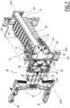
- the locking mechanism 80 comprises a safety bar 120, movable between a locking position, in which the safety bar prevents the movement of the handles 84 from their locking position to their unlocking position, and an unlocking position, in which the safety bar does not prevent the movement of the handles and in which all of the circuit breakers 72 are switched to the open configuration, i.e. in which the cut-off device 70 is switched to the open configuration.
- the safety bar 120 extends along a longitudinal axis X120 parallel to the axis X30.
- the safety bar 120 is movable in translation, along a bar translation axis Z120 parallel to the perforated faceplate 44 near which the circuit breakers 72 are installed.
- the bar translation axis Z120 is furthermore perpendicular to the width axis X30 of the branch box 30.
- the bar translation axis Z120 is parallel to the height axis Z30 of the box and perpendicular to the handle axis Y84.
- the safety bar 120 extends partially outside the housing 32, and is operable, from outside the housing, by a user between its locking and unlocking positions.
- the safety bar 120 comprises an external part 122, comprising two external wings 124 and a rod 126, each external wing 124 being arranged close to a cheek 36 and the rod 126 extending between the external wings over the entire width of the openwork faceplate 44, parallel to the width axis X30 and along the longitudinal axis X120.
- the external part 122 advantageously extends outside the housing 32.
- the safety bar 120 also comprises two internal wings 128, together forming an internal part of the safety bar, each internal wing being carried by a support 130 of the locking mechanism 80, the support 130 being carried by a cheek. Only one internal wing is visible in the figures, but the position of the other internal wing is deduced from the overall symmetry of the safety bar 120 with respect to a plane perpendicular to the axis X120 and median between the external wings 124.
- each internal wing 128 extends, parallel to the axis Y30, in the extension of an external wing 124 inside the housing 32.
- each support 130 is snapped into a cheek 36.
- the external part 122 extends from the internal part of the safety bar through the window 46 of the openwork faceplate 44.
- the translation of the safety bar 120 between its locking and unlocking positions is guided by the supports 130, on which the internal wings 128 slide and are guided by shape cooperation.
- each internal wing 128 comprises a rack 132, which extends parallel to the bar translation axis Z120.
- slots 134 are provided between the internal wings 128 and the external wings 124.
- the rod 126 of the external part 122 comes into contact with these switching levers, which causes them to tilt into the open position.
- the rod 126 impacts the switching levers.
- the switching levers 74 are prevented from tilting into the closed position by being blocked against the rod 126 of the external part 122.
- the cut-off device 70 is in the open configuration.
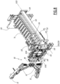
- the safety bar 120 therefore makes it possible to switch the cutting device 70 into the open configuration simply and quickly, by lowering its rod 126 from the high position shown in Figure 7 and on insert a) of the Figure 9 at the low position shown in the figure 8 and on inserts b) and c) of the figure 9 .
- the locking mechanism 80 comprises a blocking device 140, driven by the safety bar 120.
- the blocking device is provided to block the translation of the handles 84 when the safety bar 120 is in the locking position, and not to block the translation of the handles when the safety bar is in the unlocking position.
- the locking device 140 comprises two toothed wheels, movable in rotation, relative to the housing 32, around a wheel axis X140 perpendicular to the bar translation axis Z120 and perpendicular to the handle axis Y84.
- a wheel axis X140 perpendicular to the bar translation axis Z120 and perpendicular to the handle axis Y84.
- only one 140 toothed wheel is shown.
- each toothed wheel 140 is associated with a cheek 36 and a handle 84.
- the supports 130 therefore carry the safety bar 120 and the toothed wheels 140, which are assembled together.
- Each toothed wheel 140 comprises, on its peripheral surface S140, several teeth 142 engaged with the rack 132 of an internal wing 128 of the safety bar 120.
- a translation of the safety bar around the axis Z120 causes a rotation of the toothed wheels 140 around the axis Z140.
- Each toothed wheel 140 comprises two grooves 144, which extend from its peripheral surface S140 towards the wheel axis X140.
- the grooves 144 extend along groove axes X144 radial to the wheel axis X140.
- the two grooves 144 extend along groove axes X144 perpendicular to each other, that is to say separated by an angular sector of angle equal to 90°.
- the toothed wheel 140 carried by a cheek 36 is aligned, along the axis of width X30, with the pins 88 of the handle 84 associated with this toothed wheel.
- the two grooves 144 extend along groove axes X144 that intersect, but are not perpendicular to, the handle axis Y84.
- the handle 84 associated with a toothed wheel is locked in the locking position because one of the pins 88 of the handle is in contact with the peripheral surface S140 of the toothed wheel.
- this pawn is the central pawn of the handle. This pawn 88 being in abutment against the peripheral surface S140, it cannot engage in a groove 144 and the handle is prevented from translating into the unlocked position.
- the other pins 88 of the handle are offset from the toothed wheel.
- offset it is meant that the projection of the pins 88 on an axis perpendicular to the handle axis X84 and perpendicular to the wheel axis X140, that is to say, in the example, on an axis parallel to the axis Z30, has no intersection with the projection of the toothed wheel on this same axis.
- the two other pins 88 are the peripheral pins and are located on either side of the toothed wheel, along the axis Z30.
- a first groove 144 extends along a groove axis X144 parallel to the handle axis Y84 and a second groove extends along a groove axis perpendicular to the handle axis.
- the handle 84 associated with a toothed wheel can tilt from its locking position to its unlocked position, because two of the three pins 88 are offset from the toothed wheel and the third pin 88, corresponding to the pin which is in abutment against the peripheral surface S140 when the safety bar 120 is in the locked position, is aligned with the groove 144 extending parallel to the handle axis Y84.
- this pin can engage in this groove 144, and does not prevent the movement of the handle from its locking position to its unlocked position.
- the safety bar 120 is shown in the locked position and the switching levers 74 are shown in the open position.
- the safety bar is shown in the unlocked position. On these two inserts, the safety bar hides the switching levers 74.
- the openwork faceplate 44 engages in the slots 134 formed between the internal wings 128 and the external wings 124 of the safety bar.
- disassembly of the openwork faceplate is impossible, even after removal of the screws 45, because the movement of the faceplate in the plane of the faceplate, denoted P44, is prevented by its contact with the frame of the box 32, more precisely with the crosspieces 34, and with the safety bar 120, as better seen in the Figure 2 , and the movement of the faceplate perpendicular to the plane of the faceplate P44, that is to say in a direction away from the box 30, is prevented by the contact of the faceplate with the external wings 124 of the safety bar, at the level of the slot 134.
- the plane of the faceplate P44 is parallel to the bar translation axis Z120. Furthermore, in the example, this plane is perpendicular to the depth axis Y30. Thus, in the example, the direction of distance of the box 30 is along the depth axis Y30.
- the projection of the external part 122 of the safety bar i.e. the external wings 124 and the rod 126, in the plane of the faceplate P44, is contained in the window 46 of the openwork faceplate.
- the openwork faceplate 44 does not engage in the slots 134.
- the disassembly of the openwork faceplate is made possible by a translational movement of the openwork faceplate perpendicular to the plane of the faceplate, i.e. in a direction away from the box 30, parallel to the axis Y30.
- the external part 122 of the safety bar passes inside the window 46.
- the openwork breastplate 44 can only be removed when the safety bar 120 is in the unlocked position.
- the openwork faceplate 44 is particularly easy to dismantle, since its dismantling only requires tilting the safety bar into the unlocked position and removing the screws 45.
- the slots 134 have a height H134, measured in the plane of the faceplate P44 along the bar translation axis Z120, at least equal to 50% of the height H124 of the external wings 124.
- H134 the height of the faceplate P44 along the bar translation axis Z120.
- the height H46 of the window 46 of the openwork faceplate is substantially equal, excluding the operating clearance, to the height H124 of the external wings 124.
- the height of the external part 122 of the safety bar 120 is substantially equal to the height of the window 46, without being greater.
- the height of the external part 122 of the security bar 120 is strictly less than the height H46 of the window 46.
- handles 84 can be operated from outside the branch box 30 is particularly advantageous, since this makes it possible to mount and dismount the branch box from the busbar 14 without having to access the interior of the box, i.e. without having to dismount one of the faceplates 40, in particular the openwork faceplate 44.
- the actuation of the handles 84 is only possible when the cut-off device 70 is in the open configuration, which is particularly advantageous. Indeed, the dismantling of the branch box 30 is thus secured, because it is not possible to dismantle the branch box from the busbar 14 when the electrical circuits connected thereto are electrically supplied.
- the openwork faceplate 44 can only be removed when the safety bar 120 is in the unlocked position is particularly advantageous, because this allows access to the inside of the junction box 30 only when the cut-off device is in the open configuration, which is more secure. Indeed, this makes it possible to prevent access to the inside of the box when the electrical connections of the output electrical distribution device 66 are energized. Thanks to this system, it is possible to carry out maintenance operations inside the box 30 simply and safely.
- the openwork faceplate 44 is simpler and less expensive to implement than a door, which facilitates the manufacture of the junction box 30 as well as its cost.
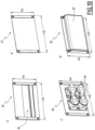
- a faceplate 40 is shown which may belong to the junction box 30.
- connection faceplate 48 is shown on insert c.
- This faceplate is in practice a faceplate supporting the electrical distribution device 66 of a junction box.
- the connection faceplate 48 thus carries four electrical sockets 68.
- the junction box of the figures 1 to 9 includes such a connection plate 48, the presence of which is deduced from the figures 1 to 3 , although this connection plate is hidden by the box in these figures, given the orientation of the box shown in these figures.
- L48 the length of the plate 48 and “l48” its width.
- connection faceplate 48 supports a portion of the electrical distribution device 66, i.e. a portion of the connectors and/or components of the electrical distribution device.
- each junction faceplate may comprise two electrical outlets 68.
- a faceplate with door 50 is shown on the insert d.
- This faceplate with door 50 is in practice an openwork faceplate 44 modified so as to further comprise a door 52.
- the door 52 is thus fixed on the openwork faceplate 44, so as to be movable between a closed position and an open position.
- the door covers the window 46 of the openwork faceplate, while remaining at a distance from the plane of the faceplate P44, so as to prevent access to the switching levers 74 of the circuit breakers 72 and to the safety bar 120, without coming into contact with the switching levers or with the safety bar.
- the door does not prevent access to the switching levers and the safety bar.
- the door 50 protects the switching levers 74 and the safety bar 120 from accidental manipulation.
- the faceplate with door 50 is not part of the connection box 30 of the figures 1 to 9 but could be mounted in place of the openwork breastplate 44. We note “L50” the length of the breastplate 50 and “l50” its width.
- the door is shown in an opaque material, i.e. it hides the circuit breakers 72 and the safety bar 120.
- the window 46 is thus not visible.
- the door 52 is made of transparent material, so that the circuit breakers and the safety bar are visible when the door is in the closed position.
- the lengths L42, L44, L48 and L50 on the one hand and the widths l42, l44, l48 and l50 on the other hand are all identical.
- the 42, 44, 48 and 50 faceplates all fit into the same envelope, in a plane defined by their length and width.
- the faceplates 42, 44, 48 and 50 form a set of faceplates, each faceplate of which makes it possible to close each of the openings 39 of the housing 32.
- each opening 39 is rectangular in shape.
- L39 the length of an opening 39, measured along an axis parallel to the axis X30, that is to say along an axis parallel to the crosspieces 34
- l39 the width of an opening 39, measured, depending on the location of the opening 39, either along an axis parallel to the axis Y30, or along an axis parallel to the axis Z30.
- All the openings 39 have an identical length L39 and an identical width l39.
- the length L39 is equal to the lengths L42, L44, L48 and L50
- the width l39 is equal to the widths l42, l44, l48 and l50.
- the shape of all the openings 39 is identical to the shape of the casings of the faceplates 40, which makes it possible to adapt the configuration of a junction box 30, by choosing the types of faceplates 40 adapted to the desired use of the box.
- the faceplates 40 When mounted on a junction box 30, the faceplates 40 are either parallel or perpendicular to the bottom 38 of the housing 32.
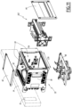
- busbar 14 a part of the busbar 14 is represented schematically by its casing, in axis lines.
- the branch box 30 is shown assuming that the busbar 14 extends horizontally, so that the connectors 16 of a group of connectors extend vertically.
- the busbar 14 is for example fixed against a wall.
- the bottom 38 of the box is vertical and the cheeks 36 are vertical.
- the box is arranged next to the busbar, as can also be seen in the Figure 1
- the solid faceplate 42, the openwork faceplate 44 and the connection faceplate 45 are respectively located at the top of the box, to the right of the box and at the bottom of the box, according to the orientation shown in Figure 11 .
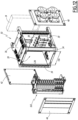
- the junction box 30 is shown in a different hypothesis than that of the Figure 11 .
- the busbar 14 extends vertically, so that the connectors 16 of a group of connectors extend horizontally.
- the busbar 14 is for example fixed against a wall.
- the bottom 38 of the box is vertical and cheeks 36 are horizontal.
- the box is arranged next to the busbar.
- the solid faceplate 42, the openwork faceplate 44 and the connection faceplate 45 are respectively located to the left of the box, at the front of the box and to the right of the box, according to the orientation shown in Figure 12 .
- a second, third, fourth and fifth embodiment of the junction box 30 are illustrated in the figures 13 to 18 .
- elements similar to those of the first embodiment have the same references and operate in the same way.
- the differences between each embodiment and the previous one(s) are mainly described.
- a component is mentioned in the description of one of the second to fifth embodiments without being shown in the figures 13 to 18 , it corresponds to the same element represented on the figures 1 to 12 for the first embodiment.
- the second embodiment of the junction box 30 is shown in figure 13
- This embodiment can be implemented in the case of a branch box 30 suspended under the busbar 14, with the circuit breakers 72 arranged on one side of the box, and not below the box, which is the case if the branch box is according to the first embodiment.
- the openwork faceplate 44 is perpendicular to the bottom 38.
- the openwork faceplate is parallel to a solid faceplate 42.
- the circuit breakers 72 and the inert block 76 of the cut-off device 70 are then oriented perpendicularly to the circuit breakers of the first embodiment, so as to be arranged on the side of the housing comprising the openwork faceplate 44.
- the safety bar is also oriented perpendicularly to the safety bar of the first embodiment, so as to extend through the window 46 of the openwork faceplate 44.
- the bar translation axis Z120 is, in this example, parallel to the depth axis Y30 and to the handle axis Y84.
- the safety bar 120 being assembled with the supports 130 and the toothed wheels 140, these elements are also oriented perpendicularly with respect to the supports and the toothed wheels of the first embodiment.
- the safety bar 120, the two supports 130, the toothed wheels 140 and the circuit breakers 72 and the inert block 76 of the cut-off device 70, which together form a functional assembly 160, are arranged on one side of the housing comprising the openwork faceplate 44, and the functional assembly 160 is oriented perpendicularly relative to the functional assembly of the first embodiment.
- the operation of the functional assembly 160 does not depend on its orientation with respect to the handles 84.
- a functional assembly 160 comprises a cutting device 70.
- this change in orientation and positioning of the safety bar 120 and the toothed wheels 140 does not change the operation of the locking mechanism 80, and more particularly, does not change the interaction between the handles 84 and the locking device 140 formed by the toothed wheels.
- the pins 88 are advantageously positioned, on the handles 84, so that in the orientation of the second embodiment, when the safety bar 120 is in the locking position, one of the two peripheral pins can engage in one of the two grooves 144 of the toothed wheels, and so that, when the safety bar is in the unlocking position, this same peripheral pin is in abutment against the peripheral surface S140.
- the locking of the handles 84 is thus ensured by the toothed wheels 140 in the same way as in the first embodiment.
- the groove axis X144 extending parallel to the handle axis Y84 in the configuration of the first embodiment, extends perpendicular to the handle axis Y84 in the configuration of the second embodiment.
- the toothed wheels 140 each comprise two grooves 144 arranged perpendicular to each other is particularly advantageous, because this allows that, whatever the orientation of the toothed wheels 140, and therefore of the safety bar 120 and the circuit breakers 72, one of the two grooves 144 of a wheel is always oriented parallel to the handle axis Y84, when the safety bar is in the locking position. Thanks to this versatility, the circuit breakers 72 and the safety bar 120 can be installed on one side of the housing parallel, or perpendicular, to the bottom 38, which makes the junction box 30 modular and customizable.
- the branch box of the second embodiment of the invention is shown assuming that the busbar 14 extends horizontally, so that the connectors 16 of a group of connectors extend horizontally.
- the busbar 14 is for example fixed to a ceiling.
- the bottom 38 of the box is horizontal and the cheeks 36 are vertical.
- the box is suspended under the busbar.
- the solid faceplate 42, the openwork faceplate 44 and the connection faceplate 45 are respectively located to the left of the box, to the right of the box and at the bottom of the box, according to the orientation shown in Figure 14 .
- junction boxes 30 of the first and second embodiments comprise the same parts, and that only the position of these parts is different.
- the junction box 30 includes two openwork faceplates which are not visible but of the type of faceplate 44 shown in insert a) of the Figure 10 , these two faceplates being arranged parallel to each other and perpendicular to the bottom 38, on two opposite sides of the junction box.
- the junction box 30 also comprises two cut-off devices 70 each comprising circuit breakers 72 arranged on the two sides of the housing 32 comprising the openwork faceplates.
- the locking mechanism then comprises two safety bars 120, each safety bar extending through the window 46 of one of the two openwork faceplates 44 and capable of switching one of the two cut-off devices 70, and four toothed wheels 140, each safety bar driving two toothed wheels.
- the junction box 30 comprises two safety bars and two pairs of toothed wheels arranged mirror-image to each other.
- the third embodiment is shown in side view at Figure 15 , with two functional assemblies 160, a cheek 36 being masked and a handle 84 being shown in transparency, which is shown by dotted lines, for greater visibility.
- This third embodiment is a variant of the second embodiment.
- the handle 84 When a safety bar is in the unlocking position and a safety bar is in the locking position, the translation of the handles 84 towards their unlocking position is prevented by the blocking of one of the pins 88 of each handle against the peripheral surface S140 of one of the toothed wheels 140. It is therefore particularly advantageous for the handle 84 to comprise two peripheral pins 88.
- the dismantling of the branch box 30 from the busbar 14 is only possible when the two safety bars 120 of the two functional assemblies 160 are in the unlocked position, which ensures that the box can only be dismantled when the two cut-off devices are in the open configuration.
- This embodiment is particularly advantageous to implement in the case of a junction box 30 suspended under the busbar 14, in a hypothesis similar to that shown in figure 14 for the second embodiment, with the circuit breakers 72 of the two functional assemblies 160 arranged on two opposite sides of the box.
- This configuration makes it possible in particular to separately protect several circuits connected to the electrical distribution device 66, the electrical power supply of each circuit being able to be easily cut by a safety bar 120 independently of the other circuit.
- this configuration has the advantage of being particularly compact, which facilitates its implementation in an industrial environment.
- a junction box 30 according to the fourth embodiment of the invention is shown in figure 16 .
- the cheeks 36 are generally rectangular and the length denoted L36 of the cheeks 36 is approximately equal to twice the width denoted l36 of the cheeks 36.
- the cheeks 36 therefore have four corners, two long edges of length L36 and two short edges of width l36.
- the housing 32 comprises four crosspieces 34, parallel to each other and which extend parallel to the axis X30.
- the four crosspieces 34 and the bottom 38 together constitute the frame of the junction box 30.
- the four crosspieces and the bottom 38 are arranged so that the frame of the box is a rectangular parallelepiped, so that three crosspieces extend between three of the four corners of the cheeks 36 and one crosspiece extends from the center of one of the two long edges of the cheeks, between these cheeks, in practice on the front side of the box, and so that the bottom extends from the fourth corner of the cheeks, along the other long edge of the cheeks, between these cheeks, practically on the rear side of the case.
- the other four sides 32A, 32B, 32C and 32D correspond respectively to the upper, lower, front and rear side of the housing 32, depending on the orientation of the figure 16 .
- the bottom 38 partially closes the rear side 32D of the case.
- the sides 32A, 32B, 32C and 32D of the housing 32 thus comprise five distinct openings 39 which are not closed by the bottom 38, each opening 39 extending between two crosspieces 34 or between a crosspiece and the bottom 38, perpendicular to the cheeks 36.
- the five openings 39 two are perpendicular to the bottom 38. Depending on the orientation of the figure 16 , these two openings are located above and below the housing 32, i.e. on the sides 32A and 32B.
- the five openings 39 two others are parallel to the bottom 38 and located one above the other on the front side 32C, i.e. on the side of the housing opposite the side partially closed by the bottom.
- another is parallel to the bottom 38 and located in the same plane as the bottom, on the rear side 32D of the housing, which is partially closed by the bottom. In the example, this opening is located under the bottom 38.
- the handles 84 of the locking mechanism 80 being movable in a movement of moving away from-toward the bottom 38 between their locking position and their unlocking position, they are arranged between the bottom 38 and the opening 39 facing the bottom 38, that is to say they are carried by the cheeks 36 near the upper side 32A, according to the orientation of the figure 16 .
- the junction box 30 comprises a functional assembly 160, not shown, which is arranged either on the front side 32C, at the level of the opening 39 facing the bottom 38, or at the level of the opening 39 of the upper side 32A.
- the junction box 30 thus comprises at least one openwork faceplate 44 or a faceplate with door 50, closing the opening at the level of which the functional assembly 160 is arranged.
- the locking devices 140 cooperate with the handles 84 to allow or block the movement of the handles.
- faceplates 40 which may be solid faceplates 42, openwork faceplates 44, connection faceplates 48 and/or faceplates with door 50.
- the branch box 30 of the fourth embodiment is advantageously designed to be fixed to a busbar 14 extending horizontally, for example to a busbar 14 fixed to a wall, in a manner analogous to the hypothesis of the Figure 11 .
- a junction box 30 according to the fifth embodiment of the invention is shown in Figure 17 .
- the cheeks 36 are generally rectangular and the length L36 of the cheeks 36 is approximately equal to twice the width l36 of the cheeks.
- the housing 32 comprises four crosspieces 34, parallel to each other and which extend parallel to the axis X30. These crosspieces 34 and the bottom 38 form the frame of the junction box 30.
- the four crosspieces 34 and the bottom 38 are arranged so that the frame of the housing is a rectangular parallelepiped, so that two crosspieces extend between the two lower corners of the cheeks 36 and two crosspieces extend from the center of the two longest edges of the cheeks, between the cheeks, and so that the bottom extends from the two upper corners of the cheeks 36, between these cheeks, in practice on the upper side of the housing.
- the other four sides 32A, 32B, 32C and 32D correspond respectively to the upper, lower, front and rear side of the housing 32, depending on the orientation of the Figure 17 .
- the bottom 38 completely closes the upper side 32A of the housing.
- the sides 32B, 32C and 32D of the housing 32 thus comprise five distinct openings 39, each opening 39 extending between two crosspieces 34 or between a crosspiece and the bottom 38, perpendicular to the cheeks 36.
- the five openings 39 one is parallel to the bottom 38 and located on the lower side 32B of the housing, that is to say on the side of the housing opposite the side closed by the bottom 38.
- four others are perpendicular to the bottom 38, two of which are located one above the other on the front side 32C and two are located one above the other on the rear side 32D.
- the handles 84 of the locking mechanism 80 being movable in a movement of moving away from-toward the bottom 38 between their locking position and their unlocking position, they are arranged between the bottom 38 and the opening 39 facing the bottom 38. In the example, they are carried by the cheeks 36 near the lower side 32B, depending on the orientation of the Figure 17 . Alternatively, the handles 84 are carried by the cheeks 36 near the upper side 32B, depending on the orientation of the Figure 17 .
- the junction box 30 comprises one or two functional assemblies 160, not shown.
- the box comprises a single functional assembly 160
- this assembly is arranged either on the lower side 32B, or on the front side 32C, at the opening 39 closest to the handles 84, or on the rear side 32D, at the level of the opening 39 closest to the handles 84.
- the junction box 30 comprises at least one openwork faceplate 44 or with door 50, closing the opening at the level of which the functional assembly 160 is arranged.
- the box comprises two functional assemblies 160
- these assemblies are arranged back-to-back on the sides 32C and 32D, at the openings closest to the handles.
- the junction box 30 comprises at least two openwork faceplates 44 or with door 50, closing the openings at which the functional assemblies 160 are arranged.
- the locking devices 140 cooperate with the handles 84 to allow or block the movement of the handles.
- faceplates 40 which may be solid faceplates 42, openwork faceplates 44, connection faceplates 48 and/or faceplates with door 50.
- the branch box 30 of the fifth embodiment is advantageously designed to be fixed to a busbar 14 extending horizontally, for example to a busbar 14 fixed to a ceiling, in a manner analogous to the hypothesis of the Figure 14 .
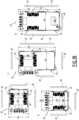
- the four inserts of the figure 18 schematically show the different ways in which the branch boxes 30 of the first to fifth embodiments of the invention can be configured.
- a junction box 30 of a first size comprises three openings 39, like the boxes of the first, second and third embodiments of the invention.
- a box of the first size comprises generally square cheeks 36, the length L36 of which is substantially equal to the width l36, and the width of which is substantially equal to the width l39 of the openings 39, which makes it possible to close all the openings 39 with the same faceplates 40.
- all the openings 39 can be closed by a faceplate 40, chosen from a solid faceplate 42, openwork 46, connection 48 or with door 50, which makes the configuration of a junction box 50 of the first size very versatile.
- the length and width of the cheeks 36 are measured in a plane perpendicular to the crosspieces 34.
- the same box of the first size can be fixed next to a busbar 12 itself fixed to a wall, as with the box of insert a), and suspended from a busbar itself fixed to a ceiling, as with the box of insert b), since only the orientation of the box differs between inserts a) and b).
- a junction box 30 of a second size comprises five openings 39, like the boxes of the fourth and fifth embodiments of the invention.
- a box of the second size comprises generally rectangular cheeks 36, the length L36 of which is approximately twice the width l36, the width of which is substantially equal to the width l39 of the openings 39, and the length L36 of which corresponds to approximately twice the width l42, l44, l48 and l50 of the faceplates 40, which makes it possible to close all the openings 39 with the same faceplates 40.
- all the openings 39 can be closed by a faceplate 40, chosen from a solid faceplate 42, openwork 46, connection 48 or with door 50, which makes the configuration of a junction box 50 of the second size very versatile.
- the length and width of the cheeks 36 are measured in a plane perpendicular to the crosspieces 34.
- the second size box of insert c) can be fixed next to a busbar 12 itself fixed to a wall, and the second size box of insert d) can be suspended from a busbar itself fixed to a ceiling.
- the second openwork faceplate 44 or 50 is for example associated with additional circuit breakers, arranged at another opening 39 than the opening near which the functional assembly 160 is arranged.
- additional circuit breakers are connected downstream to the electrical distribution device 66, and are preferentially connected upstream to the circuit breakers 72 of the cut-off device 70, so that, when the safety bar 120 is in the unlocked position, the additional circuit breakers are not electrically powered by the circuit breakers 72, which are themselves switched to the open configuration.
- a particularly advantageous consequence caused both by the operation of the locking mechanism 80, and more precisely by the fact that the locking devices 140 can lock the handles 84 independently of their orientation, and by the versatility of the configuration of the first and second size boxes 30, is that it is possible to very simply adapt the configuration of a branch box 30 during its implementation in an electrical installation 10, without having to foresee its orientation at the time of manufacture of the branch box.
- a user finds that it would be more practical, to access the switching levers 74 and the safety bar 120, to arrange the functional assembly on a side of the box 32 facing downwards, rather than on a side of the box facing a wall, then the user simply needs to disconnect the cables connected to the circuit breakers 72, modify the position of the functional assembly 160, swap two faceplates 40, including the openwork faceplate 44 or 50 associated with the functional assembly, and reconnect the cables connected to the circuit breakers 72, to modify the configuration of the branch box. Since this change can be carried out on site, i.e. close to the electrical installation 10, and does not require the use of new parts, it is particularly simple and inexpensive to implement.
- the locking mechanism 80 comprises a different number of hooks 82, for example two or six hooks, which may be arranged on the cheeks 36 or at other locations of the housing 32, so as to allow the housing to be fixed to the busbar 14.
- the mechanism comprises one hook per cheek 36, or two hooks per cheek 36 and two hooks arranged on the bottom 38.
- the locking mechanism 80 comprises a different number of handles 84, for example a single handle driving all of the hooks 82.
- the junction box 30 is adapted accordingly, for example by providing only a single toothed wheel 140 and a single latch 100.
- the hooks 82 are not carried by the cheeks 36 but, for example, by the bottom 38.
- each handle 84 comprises a different number of pawns 88, for example a single pawn, two pawns or at least four pawns.
- the safety bar 120 is rotatable about an axis perpendicular to the handle axis Y84 between its locking position and its position unlocking, and the racks 132 are replaced by pinions rotating the toothed wheels 140.
- the locking device 140 comprises a single groove 144, intended to be parallel to the handle axis Y84 when the safety bar 120 is in the unlocked position.
- the locking device 140 comprises a single toothed wheel 140, allowing the locking of a single handle 84.
- the safety bar 120 when moved to the unlocked position, switches the circuit breakers 72 to the open configuration without acting on their switching levers 74, for example by actuating an opening mechanism internal to the circuit breakers.
- the disconnecting device 70 comprises a disconnect switch and the safety bar 120, when moved to the unlocked position, isolates the input electrical connectors 62 from the output electrical distribution device 66 by actuating the disconnect switch.
- the disconnecting device 70 may not comprise circuit breakers 72.
- the safety bar 120 further comprises an added part, fixed to the 126, provided to locally widen the rod 126 and facilitate the tilting of the switching levers 74 when the safety bar 120 is tilted into the unlocked position.
Landscapes
- Engineering & Computer Science (AREA)
- Power Engineering (AREA)
- Connection Or Junction Boxes (AREA)
- Patch Boards (AREA)
Claims (10)
- Abzweigkasten (30) für Sammelschiene (14) umfassend:- ein Gehäuse (32) mit einer im Wesentlichen rechteckigen Parallelepipedform, umfassend:∘ mindestens zwei zueinander parallele Querstreben (34);∘ einen Boden (38);∘ zwei Wangen (36), parallel zueinander und senkrecht zum Boden, die zwei gegenüberliegende Seiten des Gehäuses verschließen, und∘ mindestens drei separate Öffnungen (39), wobei sich jede Öffnung senkrecht zu den Wangen zwischen zwei Querstreben oder zwischen einer Querstrebe und dem Boden erstreckt,- einen Verriegelungsmechanismus (80), der konfiguriert ist, um die Verriegelung des Gehäuses (32) an einer Sammelschiene (14) ermöglicht, und- ein elektrisches Verteilungssystem (60), umfassend:∘ elektrische Eingangsverbinder (62), die konfiguriert sind, um elektrisch mit der Sammelschiene verbunden zu sein, wenn das Gehäuse an der Sammelschiene verriegelt ist;∘ eine Ausgangsstromverteilungsvorrichtung (66), die konfiguriert ist, um einen stromabwärtigen Stromkreis mit Strom zu versorgen; und∘ mindestens eine Unterbrechungsvorrichtung (70), die in der Nähe einer Öffnung des Gehäuses angeordnet und konfiguriert ist, um umschaltbar zu sein zwischen:■ einer geschlossenen Konfiguration, in der die Unterbrechungsvorrichtung die elektrischen Eingangsverbinder mit der Stromverteilungsvorrichtung verbindet; und■ einer offenen Konfiguration, in der die Unterbrechungsvorrichtung die elektrischen Eingangsverbinder von der Stromverteilungsvorrichtung isoliert,wobei, in der zusammengebauten Konfiguration des Abzweigkastens (30) jede Öffnung (39) des Gehäuses (32) durch eine Frontplatte (40) verschlossen ist,wobei jede Frontplatte ausgewählt ist aus einer Gruppe von unterschiedlichen Frontplatten, umfassend:- eine massive Frontplatte (42);- eine Verbindungsfrontplatte (48);- eine durchbrochene Frontplatte (44), umfassend ein Fenster (46); und- ein Frontplatte mit Tür (50), umfassend ein Fenster (46),wobei, von den Frontplatten (40) mindestens eine Frontplatte eine durchbrochene Frontplatte (44) oder eine Frontplatte mit Tür (50) ist,wobei von den Frontplatten (40) mindestens eine Frontplatte eine Verbindungsfrontplatte (48) ist, die die Ausgangsstromverteilungsvorrichtung (66) oder einen Teil der Ausgangsstromverteilungsvorrichtung trägt,dadurch gekennzeichnet, dasssich die Querstreben (34) zwischen den zwei Wangen (36) erstrecken,sich die Frontplatten (40) senkrecht zu den Wangen (36) zwischen zwei Querstreben (34) erstrecken,jede Frontplatte (40) der Frontplattenanordnung konfiguriert ist, um alle Öffnungen (39) des Gehäuses (32) zu verschließen,und dass die Unterbrechungsvorrichtung (70) auf einer Seite (32A, 32B, 32C, 32D) des Gehäuses angeordnet ist, das eine durchbrochene Frontplatte (44) oder eine Frontplatte mit Tür (50) umfasst.
- Abzweigkasten (30) nach Anspruch 1, wobei eine Länge (L36) der Wangen (36) im Wesentlichen gleich wie eine Breite (I36) der Wangen ist, oder wobei eine Länge (L36) der Wangen (36) etwa doppelt so groß wie eine Breite (I36) der Wangen ist, wobei die Breite der Wangen im Wesentlichen gleich wie eine Breite (I39) der Öffnungen (39) ist.
- Abzweigkasten (30) nach einem der vorherigen Ansprüche, umfassend mindestens zwei funktionelle Anordnungen (160), die auf zwei gegenüberliegenden Seiten (32A, 32B, 32C, 32D) des Gehäuses (32) angeordnet sind, jede funktionelle Anordnungen umfassend eine Unterbrechungsvorrichtung (70) und eine Sicherheitsleiste (120), wobei die Sicherheitsleiste beweglich ist zwischen einer Entriegelungsposition, in der die Unterbrechungsvorrichtung der funktionellen Anordnung in einer offenen Konfiguration ist, und einer Verriegelungsposition.
- Abzweigkasten (30) nach Anspruch 3, wobei der Verriegelungsmechanismus (80) einen Griff (84) umfasst, der beweglich ist zwischen einer Verriegelungsposition, in der der Abzweigkasten (30) konfiguriert ist, um an der Sammelschiene (14) verriegelt zu sein, und einer Entriegelungsposition, in der der Abzweigkasten konfiguriert ist, um nicht an der Sammelschiene verriegelt zu sein, und wobei, wenn die Sicherheitsleiste (120) von mindestens einer funktionellen Anordnung (160) in der Verriegelungsposition ist, diese Sicherheitsleiste die Bewegung des Griffs aus seiner Verriegelungsposition in seine Entriegelungsposition verhindert.
- Abzweigkasten (30) nach einem der vorherigen Ansprüche, wobei:- die Wangen (36) generell rechteckig sind und vier Ecken, zwei lange Ränder und zwei kurze Ränder aufweisen, wobei eine Länge (L36) der langen Ränder der Wangen ungefähr gleich wie das Zweifache einer Breite (ℓ36) der kurzen Ränder der Wangen ist;- das Gehäuse vier Querstreben (34) umfasst, wovon:∘ sich drei Querstreben zwischen den Wangen zwischen drei der vier Wangenecken erstrecken und eine Querstrebe sich zwischen den Wangen von der Mitte einer der zwei langen Wangenränder aus erstreckt, wobei sich der Boden zwischen den Wangen von der vierten Wangenecke aus entlang des anderen langen Wangenrands erstreckt; oder∘ sich zwei Querstreben zwischen den Wangen zwischen zwei der Wangenecken erstrecken und zwei Querstreben sich zwischen den Wangen von der Mitte der zwei langen Wangenränder aus erstrecken, wobei sich der Boden zwischen den Wangen von den zwei anderen Wangenecken aus erstreckt,- das Gehäuse fünf separate Öffnungen (39) aufweist, wobei die fünf Öffnungen über die vier Seiten (32A, 32B, 32C, 32D) des Gehäuses (32) verteilt sind, die nicht durch die Wangen verschlossen sind; und- jede Öffnung durch eine Frontplatte (40) verschlossen ist.
- Abzweigkasten (30) nach einem der vorherigen Ansprüche, wobei jede Frontplatte (40) entweder parallel oder senkrecht zu dem Boden (38) des Gehäuses (32) ist.
- Abzweigkasten (30) nach einem der vorherigen Ansprüche, wobei das Fenster (46) der durchbrochenen Frontplatte (44) oder der Frontplatte mit Tür (50) konfiguriert ist, damit ein Schalthebel (74) der Unterbrechungsvorrichtung (70) sich durch das Fenster erstreckt und von außerhalb des Gehäuses (32) geschaltet werden kann, wobei der Schalthebel zwischen einer offenen Position, in der die Unterbrechungsvorrichtung in einer offenen Konfiguration ist, und einer geschlossenen Position, in der die Unterbrechungsvorrichtung in einer geschlossenen Konfiguration ist, umschaltbar ist.
- Abzweigkasten (30) nach einem der vorherigen Ansprüche, wobei die Verbindungsfrontplatte (48) mindestens eine elektrische Steckdose (68) umfasst.
- Abzweigkasten (30) nach einem der vorherigen Ansprüche, wobei die Frontplatten (40) der Frontplattenanordnung konfiguriert sind, um die Öffnungen (39) des Gehäuses (32) in mindestens zwei verschiedenen Konfigurationen des Abzweigkastens (30) zu verschließen, zwischen denen die Verbindungsfrontplatte (48) und/oder die durchbrochene Frontplatte (44) oder die Frontplatte mit Tür (50) in Bezug auf den Boden (38) unterschiedlich ausgerichtet sind.
- Abzweigkasten (30) nach einem der vorherigen Ansprüche, wobei die Frontplatten (40) der Frontplattenanordnung konfiguriert sind, um die Öffnungen (39) des Gehäuses (32) in mindestens zwei verschiedenen Konfigurationen des Abzweigkastens (30) zu verschließen, wobei in einer ersten Konfiguration des Abzweigkastens der Boden (38) eine obere Seite (32A) des Gehäuses vollständig verschließt, und wobei in einer zweiten Konfiguration des Abzweigkastens, der Boden eine Rückseite (32D) des Abzweigkastens vollständig oder teilweise verschließt.
Applications Claiming Priority (1)
| Application Number | Priority Date | Filing Date | Title |
|---|---|---|---|
| FR2106265A FR3124033B1 (fr) | 2021-06-14 | 2021-06-14 | Coffret de dérivation pour jeu de barres |
Publications (3)
| Publication Number | Publication Date |
|---|---|
| EP4106122A1 EP4106122A1 (de) | 2022-12-21 |
| EP4106122C0 EP4106122C0 (de) | 2025-06-04 |
| EP4106122B1 true EP4106122B1 (de) | 2025-06-04 |
Family
ID=77999050
Family Applications (1)
| Application Number | Title | Priority Date | Filing Date |
|---|---|---|---|
| EP22178628.8A Active EP4106122B1 (de) | 2021-06-14 | 2022-06-13 | Abzweigkasten für sammelschienen |
Country Status (3)
| Country | Link |
|---|---|
| EP (1) | EP4106122B1 (de) |
| CN (1) | CN115483617A (de) |
| FR (1) | FR3124033B1 (de) |
Family Cites Families (3)
| Publication number | Priority date | Publication date | Assignee | Title |
|---|---|---|---|---|
| US3301989A (en) * | 1965-07-02 | 1967-01-31 | Gen Electric | Handle assembly for circuit breakers |
| CN110752567B (zh) * | 2019-10-29 | 2021-09-21 | 威腾电气集团股份有限公司 | 具有三重联锁功能的插接箱 |
| CN112420419B (zh) * | 2020-11-09 | 2023-05-12 | 威腾电气集团股份有限公司 | 一种具有联动锁定功能的插接箱 |
-
2021
- 2021-06-14 FR FR2106265A patent/FR3124033B1/fr active Active
-
2022
- 2022-06-13 EP EP22178628.8A patent/EP4106122B1/de active Active
- 2022-06-14 CN CN202210668221.0A patent/CN115483617A/zh active Pending
Also Published As
| Publication number | Publication date |
|---|---|
| EP4106122A1 (de) | 2022-12-21 |
| EP4106122C0 (de) | 2025-06-04 |
| FR3124033B1 (fr) | 2024-01-05 |
| CN115483617A (zh) | 2022-12-16 |
| FR3124033A1 (fr) | 2022-12-16 |
Similar Documents
| Publication | Publication Date | Title |
|---|---|---|
| EP0407241B1 (de) | Lösbare Platine zur Halterung von elektrischen Geräten für eine Leistungsverteilereinrichtung | |
| EP2930803B1 (de) | Einheit zum positionieren der einschübe für eine schaltanlage, eine solche einheit umfassende schaltanlage und montageverfahren dieser einheit | |
| EP0869594B1 (de) | Motoransteuerbaugruppe | |
| CA1262182A (fr) | Systeme et colonne de distribution pour appareils electriques interrupteurs | |
| FR2955425A1 (fr) | Panneau porte-fusibles isolant configurable | |
| EP1885036B1 (de) | Verteilereinheit für elektrische Anlage | |
| EP4106122B1 (de) | Abzweigkasten für sammelschienen | |
| EP4106120B1 (de) | Abzweigkasten für sammelschienen | |
| EP4106121B1 (de) | Abzweigkasten für sammelschienen | |
| FR2653607A1 (fr) | Dispositif pour la realisation d'ensembles pour la commande et la protection de circuits electriques basse tension. | |
| EP2605349A1 (de) | Aufbau zum Tragen eines Schalt-oder Steuergerätes eines mittelspannungs Schaltfeldes | |
| EP2369700B1 (de) | Elektrischer Verteiler- oder Schaltkasten, der mit Schienenführungen für Gleitzapfen ausgestattet ist | |
| EP0351279A1 (de) | Verfahren zur Montage von mindestens einem elektrischen Gerät auf einem Träger. | |
| EP0233420B1 (de) | Trennbare Stromentnahmevorrichtung auf einer Verteilsäule mit Sammelschiene | |
| WO2020141270A1 (fr) | Module de distribution électrique compartimenté par des cloisons comportant des canaux de ventilation et/ou de passage de câbles de commande | |
| EP3255732B1 (de) | Elektrische verbindungsklemme, die einen verbindungshebel umfasst, und entsprechende elektrische geräte | |
| FR2708392A1 (fr) | Cellule moyenne tension sous enveloppe métallique avec disjoncteur auto-sectionneur. | |
| CH716357B1 (fr) | Appareil modulaire électrique muni d'un élément de blocage. | |
| FR3020506A1 (fr) | Borne de connexion electrique multi-conducteurs | |
| FR2960697A1 (fr) | Chassis de montage pour appareils electriques | |
| EP4277044A1 (de) | Verbindungsvorrichtung und elektrische schalttafel mit einer solchen vorrichtung | |
| EP4277055A1 (de) | Verbindungsvorrichtung und elektrische schalttafel mit einer solchen vorrichtung | |
| EP4277053A1 (de) | Verbindungsvorrichtung und elektrische schalttafel mit einer solchen vorrichtung | |
| FR3135361A1 (fr) | Dispositif de distribution de courant et tableau électrique comprenant un tel dispositif | |
| FR2555393A1 (fr) | Armoire pour cablage electrique, notamment electronique |
Legal Events
| Date | Code | Title | Description |
|---|---|---|---|
| PUAI | Public reference made under article 153(3) epc to a published international application that has entered the european phase |
Free format text: ORIGINAL CODE: 0009012 |
|
| STAA | Information on the status of an ep patent application or granted ep patent |
Free format text: STATUS: THE APPLICATION HAS BEEN PUBLISHED |
|
| AK | Designated contracting states |
Kind code of ref document: A1 Designated state(s): AL AT BE BG CH CY CZ DE DK EE ES FI FR GB GR HR HU IE IS IT LI LT LU LV MC MK MT NL NO PL PT RO RS SE SI SK SM TR |
|
| STAA | Information on the status of an ep patent application or granted ep patent |
Free format text: STATUS: REQUEST FOR EXAMINATION WAS MADE |
|
| 17P | Request for examination filed |
Effective date: 20230526 |
|
| RBV | Designated contracting states (corrected) |
Designated state(s): AL AT BE BG CH CY CZ DE DK EE ES FI FR GB GR HR HU IE IS IT LI LT LU LV MC MK MT NL NO PL PT RO RS SE SI SK SM TR |
|
| GRAP | Despatch of communication of intention to grant a patent |
Free format text: ORIGINAL CODE: EPIDOSNIGR1 |
|
| STAA | Information on the status of an ep patent application or granted ep patent |
Free format text: STATUS: GRANT OF PATENT IS INTENDED |
|
| RIC1 | Information provided on ipc code assigned before grant |
Ipc: H02G 5/08 20060101AFI20250212BHEP |
|
| INTG | Intention to grant announced |
Effective date: 20250224 |
|
| GRAS | Grant fee paid |
Free format text: ORIGINAL CODE: EPIDOSNIGR3 |
|
| GRAA | (expected) grant |
Free format text: ORIGINAL CODE: 0009210 |
|
| STAA | Information on the status of an ep patent application or granted ep patent |
Free format text: STATUS: THE PATENT HAS BEEN GRANTED |
|
| AK | Designated contracting states |
Kind code of ref document: B1 Designated state(s): AL AT BE BG CH CY CZ DE DK EE ES FI FR GB GR HR HU IE IS IT LI LT LU LV MC MK MT NL NO PL PT RO RS SE SI SK SM TR |
|
| REG | Reference to a national code |
Ref country code: GB Ref legal event code: FG4D Free format text: NOT ENGLISH |
|
| REG | Reference to a national code |
Ref country code: CH Ref legal event code: EP |
|
| REG | Reference to a national code |
Ref country code: DE Ref legal event code: R096 Ref document number: 602022015373 Country of ref document: DE |
|
| REG | Reference to a national code |
Ref country code: IE Ref legal event code: FG4D Free format text: LANGUAGE OF EP DOCUMENT: FRENCH |
|
| U01 | Request for unitary effect filed |
Effective date: 20250616 |
|
| PGFP | Annual fee paid to national office [announced via postgrant information from national office to epo] |
Ref country code: AT Payment date: 20250721 Year of fee payment: 4 |
|
| U07 | Unitary effect registered |
Designated state(s): AT BE BG DE DK EE FI FR IT LT LU LV MT NL PT RO SE SI Effective date: 20250626 |
|
| U20 | Renewal fee for the european patent with unitary effect paid |
Year of fee payment: 4 Effective date: 20250624 |
|
| PG25 | Lapsed in a contracting state [announced via postgrant information from national office to epo] |
Ref country code: ES Free format text: LAPSE BECAUSE OF FAILURE TO SUBMIT A TRANSLATION OF THE DESCRIPTION OR TO PAY THE FEE WITHIN THE PRESCRIBED TIME-LIMIT Effective date: 20250604 |
|
| PG25 | Lapsed in a contracting state [announced via postgrant information from national office to epo] |
Ref country code: GR Free format text: LAPSE BECAUSE OF FAILURE TO SUBMIT A TRANSLATION OF THE DESCRIPTION OR TO PAY THE FEE WITHIN THE PRESCRIBED TIME-LIMIT Effective date: 20250905 Ref country code: NO Free format text: LAPSE BECAUSE OF FAILURE TO SUBMIT A TRANSLATION OF THE DESCRIPTION OR TO PAY THE FEE WITHIN THE PRESCRIBED TIME-LIMIT Effective date: 20250904 |
|
| PG25 | Lapsed in a contracting state [announced via postgrant information from national office to epo] |
Ref country code: PL Free format text: LAPSE BECAUSE OF FAILURE TO SUBMIT A TRANSLATION OF THE DESCRIPTION OR TO PAY THE FEE WITHIN THE PRESCRIBED TIME-LIMIT Effective date: 20250604 |
|
| PG25 | Lapsed in a contracting state [announced via postgrant information from national office to epo] |
Ref country code: HR Free format text: LAPSE BECAUSE OF FAILURE TO SUBMIT A TRANSLATION OF THE DESCRIPTION OR TO PAY THE FEE WITHIN THE PRESCRIBED TIME-LIMIT Effective date: 20250604 |
|
| PG25 | Lapsed in a contracting state [announced via postgrant information from national office to epo] |
Ref country code: RS Free format text: LAPSE BECAUSE OF FAILURE TO SUBMIT A TRANSLATION OF THE DESCRIPTION OR TO PAY THE FEE WITHIN THE PRESCRIBED TIME-LIMIT Effective date: 20250904 |
|
| PG25 | Lapsed in a contracting state [announced via postgrant information from national office to epo] |
Ref country code: IS Free format text: LAPSE BECAUSE OF FAILURE TO SUBMIT A TRANSLATION OF THE DESCRIPTION OR TO PAY THE FEE WITHIN THE PRESCRIBED TIME-LIMIT Effective date: 20251004 |
|
| PG25 | Lapsed in a contracting state [announced via postgrant information from national office to epo] |
Ref country code: SM Free format text: LAPSE BECAUSE OF FAILURE TO SUBMIT A TRANSLATION OF THE DESCRIPTION OR TO PAY THE FEE WITHIN THE PRESCRIBED TIME-LIMIT Effective date: 20250604 |
|
| PG25 | Lapsed in a contracting state [announced via postgrant information from national office to epo] |
Ref country code: CZ Free format text: LAPSE BECAUSE OF FAILURE TO SUBMIT A TRANSLATION OF THE DESCRIPTION OR TO PAY THE FEE WITHIN THE PRESCRIBED TIME-LIMIT Effective date: 20250604 |
|
| PG25 | Lapsed in a contracting state [announced via postgrant information from national office to epo] |
Ref country code: SK Free format text: LAPSE BECAUSE OF FAILURE TO SUBMIT A TRANSLATION OF THE DESCRIPTION OR TO PAY THE FEE WITHIN THE PRESCRIBED TIME-LIMIT Effective date: 20250604 |
|
| REG | Reference to a national code |
Ref country code: CH Ref legal event code: H13 Free format text: ST27 STATUS EVENT CODE: U-0-0-H10-H13 (AS PROVIDED BY THE NATIONAL OFFICE) Effective date: 20260127 |
|
| PG25 | Lapsed in a contracting state [announced via postgrant information from national office to epo] |
Ref country code: MC Free format text: LAPSE BECAUSE OF FAILURE TO SUBMIT A TRANSLATION OF THE DESCRIPTION OR TO PAY THE FEE WITHIN THE PRESCRIBED TIME-LIMIT Effective date: 20250604 |
|
| PLBE | No opposition filed within time limit |
Free format text: ORIGINAL CODE: 0009261 |
|
| STAA | Information on the status of an ep patent application or granted ep patent |
Free format text: STATUS: NO OPPOSITION FILED WITHIN TIME LIMIT |
|
| PG25 | Lapsed in a contracting state [announced via postgrant information from national office to epo] |
Ref country code: IE Free format text: LAPSE BECAUSE OF NON-PAYMENT OF DUE FEES Effective date: 20250613 |
|
| REG | Reference to a national code |
Ref country code: CH Ref legal event code: L10 Free format text: ST27 STATUS EVENT CODE: U-0-0-L10-L00 (AS PROVIDED BY THE NATIONAL OFFICE) Effective date: 20260416 |
|
| PG25 | Lapsed in a contracting state [announced via postgrant information from national office to epo] |
Ref country code: CH Free format text: LAPSE BECAUSE OF NON-PAYMENT OF DUE FEES Effective date: 20250630 |