EP0186571B1 - Automatische Scheinwerfereinstellung zur Korrektur des Einflusses der Veränderung der Neigung des Lichtbündels relativ zur Strasse - Google Patents
Automatische Scheinwerfereinstellung zur Korrektur des Einflusses der Veränderung der Neigung des Lichtbündels relativ zur Strasse Download PDFInfo
- Publication number
- EP0186571B1 EP0186571B1 EP85402451A EP85402451A EP0186571B1 EP 0186571 B1 EP0186571 B1 EP 0186571B1 EP 85402451 A EP85402451 A EP 85402451A EP 85402451 A EP85402451 A EP 85402451A EP 0186571 B1 EP0186571 B1 EP 0186571B1
- Authority
- EP
- European Patent Office
- Prior art keywords
- actuator
- road
- cells
- vehicle
- processing means
- Prior art date
- Legal status (The legal status is an assumption and is not a legal conclusion. Google has not performed a legal analysis and makes no representation as to the accuracy of the status listed.)
- Expired
Links
- 238000012937 correction Methods 0.000 title claims description 13
- 238000012545 processing Methods 0.000 claims description 22
- 238000004804 winding Methods 0.000 claims description 3
- 235000019557 luminance Nutrition 0.000 description 35
- 238000005286 illumination Methods 0.000 description 20
- 230000035945 sensitivity Effects 0.000 description 10
- 238000010586 diagram Methods 0.000 description 6
- 238000001514 detection method Methods 0.000 description 5
- 238000005259 measurement Methods 0.000 description 4
- 230000003287 optical effect Effects 0.000 description 4
- 241001080024 Telles Species 0.000 description 3
- 230000006399 behavior Effects 0.000 description 3
- 240000008042 Zea mays Species 0.000 description 2
- 230000001133 acceleration Effects 0.000 description 2
- 230000002159 abnormal effect Effects 0.000 description 1
- 230000003321 amplification Effects 0.000 description 1
- 239000004020 conductor Substances 0.000 description 1
- 230000009849 deactivation Effects 0.000 description 1
- 230000003247 decreasing effect Effects 0.000 description 1
- 238000013461 design Methods 0.000 description 1
- 230000000694 effects Effects 0.000 description 1
- 238000009434 installation Methods 0.000 description 1
- 238000012423 maintenance Methods 0.000 description 1
- 238000003199 nucleic acid amplification method Methods 0.000 description 1
- 239000004065 semiconductor Substances 0.000 description 1
- 230000003068 static effect Effects 0.000 description 1
Images

Classifications
-
- B—PERFORMING OPERATIONS; TRANSPORTING
- B60—VEHICLES IN GENERAL
- B60Q—ARRANGEMENT OF SIGNALLING OR LIGHTING DEVICES, THE MOUNTING OR SUPPORTING THEREOF OR CIRCUITS THEREFOR, FOR VEHICLES IN GENERAL
- B60Q1/00—Arrangement of optical signalling or lighting devices, the mounting or supporting thereof or circuits therefor
- B60Q1/0017—Devices integrating an element dedicated to another function
- B60Q1/0023—Devices integrating an element dedicated to another function the element being a sensor, e.g. distance sensor, camera
-
- B—PERFORMING OPERATIONS; TRANSPORTING
- B60—VEHICLES IN GENERAL
- B60Q—ARRANGEMENT OF SIGNALLING OR LIGHTING DEVICES, THE MOUNTING OR SUPPORTING THEREOF OR CIRCUITS THEREFOR, FOR VEHICLES IN GENERAL
- B60Q1/00—Arrangement of optical signalling or lighting devices, the mounting or supporting thereof or circuits therefor
- B60Q1/02—Arrangement of optical signalling or lighting devices, the mounting or supporting thereof or circuits therefor the devices being primarily intended to illuminate the way ahead or to illuminate other areas of way or environments
- B60Q1/04—Arrangement of optical signalling or lighting devices, the mounting or supporting thereof or circuits therefor the devices being primarily intended to illuminate the way ahead or to illuminate other areas of way or environments the devices being headlights
- B60Q1/06—Arrangement of optical signalling or lighting devices, the mounting or supporting thereof or circuits therefor the devices being primarily intended to illuminate the way ahead or to illuminate other areas of way or environments the devices being headlights adjustable, e.g. remotely-controlled from inside vehicle
- B60Q1/08—Arrangement of optical signalling or lighting devices, the mounting or supporting thereof or circuits therefor the devices being primarily intended to illuminate the way ahead or to illuminate other areas of way or environments the devices being headlights adjustable, e.g. remotely-controlled from inside vehicle automatically
- B60Q1/10—Arrangement of optical signalling or lighting devices, the mounting or supporting thereof or circuits therefor the devices being primarily intended to illuminate the way ahead or to illuminate other areas of way or environments the devices being headlights adjustable, e.g. remotely-controlled from inside vehicle automatically due to vehicle inclination, e.g. due to load distribution
-
- B—PERFORMING OPERATIONS; TRANSPORTING
- B60—VEHICLES IN GENERAL
- B60Q—ARRANGEMENT OF SIGNALLING OR LIGHTING DEVICES, THE MOUNTING OR SUPPORTING THEREOF OR CIRCUITS THEREFOR, FOR VEHICLES IN GENERAL
- B60Q2300/00—Indexing codes for automatically adjustable headlamps or automatically dimmable headlamps
- B60Q2300/10—Indexing codes relating to particular vehicle conditions
- B60Q2300/13—Attitude of the vehicle body
- B60Q2300/132—Pitch
Definitions
- the present invention relates to a device intended to automatically correct the orientation of the headlights of a vehicle, when the latter has been modified, following a change of attitude.
- the headlights of a vehicle are adjusted on the assembly line, so that they effectively illuminate the road without dazzling other users, in accordance with the highway code.
- the cut in the code beam is folded down so as to touch the ground at a distance from the vehicle of between 50 and 75 meters.
- the attitude varies and the orientation of the headlights relative to the road is thereby modified: the cut is either raised and the headlights dazzle, or turned down and they do not light far enough.
- Hydraulic or electric adjustment devices capable of carrying out both static headlamp correction and dynamic correction have long been used on certain car models. These devices generally include two sensors which permanently record the distances between the body and the front and rear wheels of the vehicle, a computer which generates a signal which is a function of the difference in said distances, and an actuator controlled by said signal to redirect the headlights to a new position for which the light beam is sent in the direction corresponding to the correct setting with respect to the road.
- the object of the present invention is to remedy these drawbacks by proposing a device for correcting the orientation of a headlight of a vehicle, which is of simple structure and of practically zero bulk.
- the control signal produced by the processing means is ineffective, so that the actuator remains stationary and the orientation of the headlamp is unchanged.
- the code beam will illuminate the road in a region closer to the vehicle. Since the direction in which the detection of the luminance is carried out varies like the direction of the beam in question, the region whose luminance is detected is therefore also close together. But since the luminance of a route point varies as the square of the distance from the light source to this point, the luminance that will be detected by the sensor in this new region will be greater than the initial luminance. The signal supplied by the sensor will therefore vary, in this case increasing.
- the variation of the signal compared to its initial value is determined by the processing means and a corresponding control signal is applied to the actuator, which rotates the projector, or possibly only the reflector thereof, by an angle such that the beam is brought back in the direction of origin compared to the road.
- a similar reasoning can be made in the case of a change of attitude due to acceleration of the vehicle.
- the beam is raised, and the automatic corrector intervenes to lower it to its initial direction.
- the device according to the invention is fully integrated inside the projector. It does not use any external electrical or hydraulic circuit.
- the projector is itself in a controlled orientation, as a function of the variation in the luminance that the sensor detects in a predetermined direction fixed relative to the projector. This corrector is therefore light, compact, economical and requires virtually no maintenance.
- the senor is constituted by an objective, such as a converging lens, and by at least one photoelectric cell mounted in the image focal plane of said lens at the image point of said region. whose luminance is to be detected, the entire converging lens and the photocell being linked in movement with the reflector.
- the headlight itself is fixed relative to the body and the reflector is movable.
- the correction device with a single photoelectric cell is not entirely satisfactory. It is in fact conceivable that even if the attitude of the car does not change, the luminance detected at the point or region considered can undergo fluctuations due to different parameters, such as the variation of the reflection coefficient of the road, due for example to the presence of colored spots or puddles, or the variation of the intensity of the spotlight. Thus, if the supply voltage of the lamps increases, the detected luminance increases. The corrector, interpreting this increase as if it were caused by a change of attitude of the car, commands the raising of the beam to an orientation such that it is likely to be dazzling.
- the senor includes a second photocell located in the focal plane of the lens, so that the latter forms the image of the road on it. a direction making a second predetermined angle with the horizontal, corresponding to a second region of the road much closer to the vehicle than the first region mentioned above.
- the processing means in this case determine the ratio of the luminances in the two chosen directions. This ratio is independent of the inherent brightness of the road and the supply voltage of the lamps.
- the processing means can be of any known type, for example of the electronic or microprocessor type.
- they are constituted by a Wheatstone bridge of which two adjacent branches are formed by the variable resistors, and chosen initially equal, of two photoelectric cells of passive type, and of which the two other branches are constituted by two fixed resistors chosen so that, when the projector is in its correct orientation, the Wheatstone bridge is balanced, the voltage collected across the Wheatstone point measurement diagonal being applied to the input of an amplifier, and l actuator being connected to the output of the latter.
- This comparator can be constituted by two potentiometers mounted on a Wheatstone bridge, and the sliders of which are integral in rotation with the reflectors of the projectors, the said potentiometer sliders being connected to the input terminals of an amplifier whose output is applied to the motor. associated with the second projector.
- the determination of the reference value of the ratio of the luminances in the two predetermined directions chosen will advantageously be carried out after having balanced, manually or automatically, the two projectors with respect to each other thanks to the comparator circuit above, the automatic corrector being off during this operation.
- the corrector with two photocells described above can have a drawback; if a fortuitous obstacle arises on the road in the angular direction of detection corresponding to the region furthest from the road, it gives this region a higher luminance.
- the ratio of the illuminations in the two angular directions chosen then increases suddenly, causing with the above device an untimely raising of the projectors.
- the idea, according to the invention of measuring the luminance in a direction intermediate between the two directions previously mentioned, and which corresponds to a region of the road situated between the most distant region and the closest region.
- the variation in luminance will be smaller in this intermediate region than in the most distant region.
- the orientation correction device will comprise a third photoelectric cell also mounted in the focal plane of the lens at a location corresponding to the image of the road in a third direction. making an angle predetermined with the horizontal, corresponding to said intermediate region.
- the processing means must therefore take into consideration the measurement of the luminance of said intermediate region.
- processing means of the microprocessor or electrical type for example the circuit envisaged above and suitably completed.
- the junction point of the first two photocells is connected, via a connecting line comprising a relay, to the junction point of the third photocell and a third resistor whose behavior is substantially identical to that of the resistance of the second cell, the other ends of which are respectively connected to the terminals of the supply diagonal of the Wheatstone bridge, said relay switching the opening of an associated switch included in an electrical circuit comprising in series the actuator (s) and the output terminals of the amplifier, as soon as a current flows in said connection line from the first to the second of the above-mentioned junction points, a diode being connected in series in said connecting line so as to oppose the flow of current in the opposite direction, the resistance of the cell associated with the most distant region being chosen greater than that of the cell associated with the close region.
- the ratio of the luminances to the distant and close regions varies according to a given law
- the ratio of the luminances to the intermediate and close regions varies according to another law.
- the first report is greater than the second report and equal to a multiple of it. This relationship between the two reports therefore makes it possible to predict, from the knowledge of the second report, what the value of the first report should normally be, and therefore the value of the luminance of the most distant region. As soon as the processing means have detected that the normal coefficient between the two reports has been exceeded, this will mean that an obstacle has arisen in said remote region, which has become very bright.
- the three photoelectric cells are in the form of elongated horizontal and parallel bands, coinciding with the respective images that the lens gives of three regions in the form of transverse road bands, of equal widths. to the lane followed by the vehicle, corresponding respectively to the three predetermined directions mentioned above, said cells having different widths which reproduce the perspective of the road.
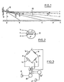
- the automatic correcting device is integrated into a headlight of a motor vehicle. It includes, as regards its optical part, an illumination sensor consisting of an objective, which can be a simple converging lens 10, and of the pivoting reflector 12 of the projector.
- the lens is integral with the reflector in pivoting motion.
- these cells are of passive type, that is to say that they are constituted by photosensitive elements whose electrical resistance varies inversely proportional to the light intensity received (photoresistors ).
- photosensitive elements whose electrical resistance varies inversely proportional to the light intensity received (photoresistors ).
- photoresistors photosensitive elements whose electrical resistance varies inversely proportional to the light intensity received
- the cells a, c, b are arranged on the reflector so as to coincide respectively with the images that the lens 10 forms on the reflector of three points A, C and B of the road, point A preferably being located at the point of Encountering the cut in the code beam (represented by line 13) with the road, when the attitude of the vehicle is normal, point B being the closest to the headlamp, and point C being at an intermediate distance.
- Points A, C, B in Figure 1 are actually regions in the form of narrow transverse road strips, widths equal to that of the lane followed by the vehicle.
- the photocells are actually in the form of horizontal bands, widths equal to those of the images of regions A, C and B of the track.
- the cells b, c, a therefore have decreasing lengths reproducing the perspective of the road.
- the position of points A, B and C is identified respectively by the angles a, and y formed by the axes OA, OB and OC with the axis OZ.
- the object of the invention is to rotate the reflector, therefore its optical axis, by an angle such that this variation d the trim is either fully compensated, or in this example counterclockwise in Figure 1.
- the orientation of the vehicle headlights is controlled by actuators, themselves controlled by signal processing means capable of comparing the ratios of the illuminations detected by the photoelectric cells at said points A, B, C, as will be explained later.
- the processing means can be of any known type, for example with a microprocessor.
- a microprocessor By way of example, an embodiment of it will be described using an electrical circuit, but it goes without saying that this example is not limiting and that the technician can imagine other embodiments.
- the circuit then comprises a Wheatstone bridge of which two adjacent branches are formed by the variable resistors r a , r b of cells a and b and the other two branches are formed by two fixed resistors 14, 16.
- Cells a and b and the resistors 14 and 16 are chosen so that the bridge is balanced when the projector is correctly adjusted.
- an electrical voltage appears across the output diagonal MN of the bridge.
- This voltage is amplified by an amplifier 18, the output signal of which is applied to two actuators 20 and 20 'associated with the projectors P and P'. According to the sign of the voltage existing at the terminals MN, the actuators will raise or lower the beams of said projectors by rotating their reflectors in the appropriate direction.
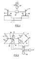
- Actuators 20 and 20 ' can be stepped. Otherwise, the actuator 20 ′ of the second projector can also be controlled by a comparator of the positions of one projector relative to the other. Position comparators are well known in the art. We will describe a non-limiting example of embodiment with reference to FIG. 4.
- This comparator comprises two potentiometers 22, 24 mounted on a Wheatstone bridge.
- the sliders 26, 28 of the potentiometers are rigidly fixed in rotation with the reflectors of the projectors P, P 'and therefore occupy a position which depends on the angular orientation of the latter.
- the voltages present on the cursors are applied to the input terminals of an amplifier 30, the output terminals of which are connected to the actuator 20, of the second projector. It will be noted that the actuator 20 of the other projector is only controlled by the assembly of FIG. 3. There is thus produced a control of the orientation of the second projector P 'relative to that of the first.
- the circuit must be able to measure not only the ratio of the luminances at points A and B, so as to eliminate the influence of the reflection coefficient of the road and the variations in intensity of the lamps of the projectors, but also the ratio of the luminances at points C and B. These two ratios are linked by a relationship as long as the operation is normal, that is to say as long as there is has no obstacle at A. Under these conditions, the circuit must produce an electrical signal which is a function of the variation in attitude angle, said signal controlling the actuator so as to rotate the associated reflector by an angle correction in the desired direction to bring the light beam in the initial direction and thus achieve the control in constant orientation illumination.
- the computer must be designed so as not to control the actuator.
- the electrical circuit of Figure 5 includes a Wheatstone bridge identical to that of Figure 3.
- the point M is connected via the winding 33 of a relay 32 and a diode 34 in series, at a point Q to which are connected the ends of the resistor r representing the photocell c and of a resistor r b '.
- the other ends U and V of the resistors r c and 36 are connected to the terminals of the supply diagonal of the Wheatstone bridge.
- the resistor r b ' is arranged to behave in a manner substantially identical to the resistor r b of the second cell. It could for example consist of a fourth cell (not shown) arranged completely in the vicinity of cell b or else, if we consider the variations of r b as negligible, in a fixed resistance equal to the average value of r b .
- the diode 34 is mounted so as to allow current to flow only from M to Q. Furthermore, the relay 32 is chosen so as to have the following behavior: when an electric current tends to flow in the QM direction, the diode prevents it and the switch 36 of the relay remains closed; when a current flows in the MQ direction, the relay is designed so that the opening of its switch 36 does not take place as long as this current remains below a threshold value; on the other hand, as soon as the current exceeds this threshold value, the force generated becomes sufficient to take off the movable blade of the switch 38, and cause the opening of the latter.
- the switch 38 is mounted in series in the supply circuit of the actuators 20 and 20 ', mounted in parallel from the output of the amplifier 16. As in the previous example, the inputs of said amplifier are connected at points M and N on the exit diagonal from the Wheatstone bridge.
- Resistors 14 and 16 are chosen so that the Wheatstone bridge is balanced.
- I A being the light intensity at A and h being the height of the projector relative to the ground.
- I B being the light intensity at B.
- angles a, ⁇ , 8 and ⁇ being very small, we can confuse their sine and their tangent with their measurement in radians.
- the sensitivity of the detection at point A is greater than that at point C, or in other words, that the variation in illumination resulting from the same variation d ⁇ is greater for a distant point than for a close point.
- the processing means can be arranged to determine the coefficient which links the sensitivities and and to compare it with the threshold value.
- the threshold is not reached, the corrective actuator control is authorized.
- the threshold is exceeded, this demonstrates the existence of an abnormal intensity variation at A, and the directional control of the headlights is inhibited.
- Figure 6 a circuit diagram which constitutes an "active" variant of the passive circuit shown in Figure 5.
- the photoelectric cells corresponding to regions A and B of the road are indicated respectively in 50a and 50b.
- These cells are of the active type and for example consist of a suitable semiconductor surface, to generate an electric current proportional to the intensity of the illumination received.
- These currents are applied to the input of current / voltage amplifiers 52a and 52b.
- the output voltages of these amplifiers are respectively applied to the inputs N and D of a divider circuit 54 arranged to effect analog division of the value of the voltage present on the terminal N by that of the voltage present on the terminal D.
- the output of the divider 54 is connected to the non-inverting input of an operational amplifier 56 mounted as a comparator.
- a voltage divider bridge constituted by two resistors 58 and 60 is intended to apply a reference voltage to the inverting input of the amplifier 56.
- the output of the amplifier 56 is intended to control the actuators 20 and 20 'to change the orientation of the associated projectors, or simply of their reflectors.
- This part of the circuit allows to generate a control signal as soon as the output of the divider 54, is the ratio between the output voltages of amplifiers 52a and 52b , which is equal to the ratio of the illuminations received by the associated cells 50a, 50b, differs from a reference value supplied by the divider bridge 58, 60.
- the sign of the output signal of the amplifier 56 varies depending on whether this ratio is higher or lower than said reference value, so that the actuators may, under the conditions explained below, bring the headlamps in the appropriate direction according to the direction of variation of the attitude of the vehicle.
- the circuit further comprises a third photoelectric cell 50c, similar to the first, the output of which is connected to the input of an amplifier 52c.
- a divider circuit 55 receives on its input N the output of the amplifier 52c, and on its input D the output of the amplifier 52b, to provide at output, after analog division, a voltage representative of the ratio between the illuminations of the cells 50c and 50b.
- An operational amplifier 62 receives on its non-inverting input the output of the divider 55, and on its inverting input, via a resistor 64, the output of the divider 54.
- Another resistor 66 is mounted between the inverting input and the output of the amplifier 62.
- Said output is also connected to the winding 33 of a relay indicated as a whole at 32, which also includes a switch 38 connected in series between the output of the amplifier 56 and the actuators 20 and 20 '.
- the purpose of this second part is to compare the ratio between the illuminations of cells 50a and 50b, provided by the divider 54, with the ratio of the illuminations of cells 50c and 50b, provided by the divider 55. More precisely, if we attribute the values R 64 and R 66 at resistors 64 and 66, and if we consider that the output voltages of the dividers 54 and 55 are respectively proportional to the ratios t and E ;, E a , E b and E c designating the illuminations respective of cells 50a, 50b and 50c, it is easily demonstrated that the output voltage of amplifier 62 changes sign for:
- any processing means such as a microprocessor-based computer, can be provided between the photoelectric cells and the actuators, making it possible to take into account any particular lighting situation of the cells.
Landscapes
- Engineering & Computer Science (AREA)
- Mechanical Engineering (AREA)
- Lighting Device Outwards From Vehicle And Optical Signal (AREA)
Claims (15)
gekennzeichnet durch
dadurch gekennzeichnet, daß
der Meßfühler für die Beleuchtungsstärke eine Sammellinse (10) und wenigstens eine fotoelektrische Zelle (a, b, c; 50a, 50b, 50c) umfaßt, die in der bildseitigen Brennpunktsebene der Linse im Bildpunkt des genannten Fahrbahnbereiches (A, B, C) angeordnet ist.
dadurch gekennzeichnet, daß
der Meßfühler zwei fotoelektrische Zellen (a, b; 50a, 50b) umfaßt, die in den zugehörigen Bildpunkten eines fahrzeugfernen und eines fahrzeugnahen Fahrbahnbereiches (A, B) angeordnet sind.
dadurch gekennzeichnet, daß
der Meßfühler eine dritte fotoelektrische Zelle (c; 50c) umfaßt, die im Bildpunkt eines zwischen den fahrzeugnahen und fahrzeugfernen Bereichen gelegenen Fahrbahnbereiches (C) angeordnet ist.
dadurch gekennzeichnet, daß
die Verarbeitungseinrichtungen so ausgebildet sind, daß sie die Betätigung der Betätigungsvorrichtung (20) verhindern, wenn das Verhältnis zwischen den Leuchtdichten der ersten und der dritten Zelle (a, c; 50a, 50c) einen Schwellenwert übersteigt.
dadurch gekennzeichnet, daß
dadurch gekennzeichnet, daß
die Verarbeitungseinrichtungen ferner ein Relais (32) umfassen, dessen Wicklung (33) in einen Zweig eingeschaltet ist, der von einem für das Verhältnis zwischen den elektrischen Widerständen (ra, rc) der ersten und der dritten Zelle (a, c) repräsentativen Strom durchflossen wird, wobei das Relais so ausgebildet ist, daß es die Speisung der Betätigungsvorrichtung unterbricht, wenn der genannte Strom einen Schwellenwert übersteigt.
dadurch gekennzeichnet, daß
dadurch gekennzeichnet, daß
die Verarbeitungseinrichtungen eine zweite Teilerschaltung (55) zum Teilen der von der zweiten und der dritten Zelle (50b, 50c) abgegebenen Spannungen und eine zweite Vergleicherschaltung (62) zum Vergleichen der von der ersten und der zweiten Teilerschaltung abgegebenen Spannungen umfassen, wobei der Ausgang der zweiten Vergleicherschaltung ein Relais (32) betätigt, das den Stromkreis zwischen der ersten Vergleicherschaltung und der Betätigungsvorrichtung wahlweise zu unterbrechen und zu schließen vermag.
dadurch gekennzeichnet, daß
die drei fotoelektrischen Zellen von der Gestalt waagerechter und paralleler Streifen von überwiegender Längserstrekkung sind, die mit den zugehörigen Bildern von drei die genannten Bereiche definierenden quergerichteten Streifen der Fahrbahn von gleicher Breite wie die vom Fahrzeug befahrene Bahn zusammenfallen.
dadurch gekennzeichnet, daß
die Verarbeitungseinrichtungen auch eine Betätigungsvorrichtung betätigen, welche die Neigung des anderen Scheinwerfers des Fahrzeuges zu ändern vermag.
dadurch gekennzeichnet, daß
die Betätigungsvorrichtungen (20, 20') Schrittmotoren sind.
dadurch gekennzeichnet, daß
dadurch gekennzeichnet, daß
die Regeleinrichtungen zu einer Wheatstone-Brückenschaltung miteinander verbundene Potentiometer (22, 24) umfassen, deren Schleifer (26, 28) mit den Scheinwerfern mechanisch drehfest verbunden sind.
dadurch gekennzeichnet, daß
die Betätigungsvorrichtung(en) eine Meigungsänderung nur des Reflektors des zugehörigen Scheinwerfers hervorzurufen vermag/vermögen.
Applications Claiming Priority (2)
| Application Number | Priority Date | Filing Date | Title |
|---|---|---|---|
| FR8419172A FR2574725B1 (fr) | 1984-12-14 | 1984-12-14 | Correcteur automatique de la direction des projecteurs lors des variations d'assiette d'un vehicule |
| FR8419172 | 1984-12-14 |
Publications (2)
| Publication Number | Publication Date |
|---|---|
| EP0186571A1 EP0186571A1 (de) | 1986-07-02 |
| EP0186571B1 true EP0186571B1 (de) | 1987-11-04 |
Family
ID=9310612
Family Applications (1)
| Application Number | Title | Priority Date | Filing Date |
|---|---|---|---|
| EP85402451A Expired EP0186571B1 (de) | 1984-12-14 | 1985-12-10 | Automatische Scheinwerfereinstellung zur Korrektur des Einflusses der Veränderung der Neigung des Lichtbündels relativ zur Strasse |
Country Status (5)
| Country | Link |
|---|---|
| US (1) | US4620267A (de) |
| EP (1) | EP0186571B1 (de) |
| JP (1) | JPH0610644B2 (de) |
| DE (1) | DE3560873D1 (de) |
| FR (1) | FR2574725B1 (de) |
Cited By (1)
| Publication number | Priority date | Publication date | Assignee | Title |
|---|---|---|---|---|
| DE19602005A1 (de) * | 1995-02-02 | 1996-08-08 | Valeo Vision | Vorrichtung zur automatischen Korrektur der Ausrichtung wenigstens eines Kraftfahrzeugscheinwerfers bei Lageänderungen des Fahrzeuges |
Families Citing this family (29)
| Publication number | Priority date | Publication date | Assignee | Title |
|---|---|---|---|---|
| JPS6293802A (ja) * | 1985-10-18 | 1987-04-30 | 東芝ライテック株式会社 | 車両用前照灯 |
| JPH0825417B2 (ja) * | 1987-08-17 | 1996-03-13 | 株式会社小糸製作所 | 二輪車輌用前照灯の照射角修正装置 |
| JPH01278848A (ja) * | 1988-05-02 | 1989-11-09 | Nissan Motor Co Ltd | 車両用前照灯装置 |
| DE4024913A1 (de) * | 1990-08-06 | 1992-02-13 | Hella Kg Hueck & Co | Verfahren und einrichtung zur regelung der leuchtweite eines kraftfahrzeugs |
| DE4024912A1 (de) * | 1990-08-06 | 1992-02-13 | Hella Kg Hueck & Co | Einrichtung zur regelung der leuchtweite eines kraftfahrzeugs |
| FR2691119B1 (fr) * | 1992-05-15 | 1994-08-19 | Valeo Vision | Correcteur automatique de l'orientation des projecteurs lors des variations d'assiette d'un véhicule. |
| GB2267564B (en) * | 1992-05-29 | 1996-03-20 | Philip John Wathen | Automatic vehicle headlamp dipswitch |
| FR2698833B1 (fr) * | 1992-12-03 | 1995-03-03 | Valeo Vision | Dispositif de correction automatique de l'orientation des projecteurs d'un véhicule automobile lors des variations d'assiette du véhicule. |
| US6822563B2 (en) | 1997-09-22 | 2004-11-23 | Donnelly Corporation | Vehicle imaging system with accessory control |
| US5877897A (en) | 1993-02-26 | 1999-03-02 | Donnelly Corporation | Automatic rearview mirror, vehicle lighting control and vehicle interior monitoring system using a photosensor array |
| FR2710014B1 (fr) * | 1993-09-15 | 1995-12-08 | Valeo Vision | Dispositif de commande automatique de l'orientation des projecteurs d'un véhicule automobile en fonction des variation d'assiette de celui-ci. |
| DE4341409C2 (de) * | 1993-12-04 | 2002-07-11 | Bosch Gmbh Robert | Einrichtung zur Regelung der Leuchtweite von Scheinwerfern von Kraftfahrzeugen |
| US6891563B2 (en) | 1996-05-22 | 2005-05-10 | Donnelly Corporation | Vehicular vision system |
| DE19525981A1 (de) * | 1995-07-17 | 1997-01-23 | Bayerische Motoren Werke Ag | Vorrichtung zur Einstellung einer vorgebbaren Beleuchtungsstärke eines Scheinwerfers in Kraftfahrzeugen |
| JP3546600B2 (ja) * | 1995-09-07 | 2004-07-28 | トヨタ自動車株式会社 | ヘッドランプの配光制御装置 |
| US7655894B2 (en) | 1996-03-25 | 2010-02-02 | Donnelly Corporation | Vehicular image sensing system |
| DE19704427A1 (de) * | 1997-02-06 | 1998-08-13 | Bosch Gmbh Robert | Einrichtung zur Regelung der Leuchtweite von Scheinwerfern von Fahrzeugen |
| DE19704466A1 (de) * | 1997-02-06 | 1998-08-13 | Bosch Gmbh Robert | Einrichtung zur Regelung der Leuchtweite von Scheinwerfern von Fahrzeugen |
| JP3518362B2 (ja) * | 1998-01-06 | 2004-04-12 | 日産自動車株式会社 | 車両のピッチ角演算装置 |
| DE10054614A1 (de) * | 2000-11-04 | 2002-05-08 | Hella Kg Hueck & Co | Einrichtung und Verfahren zur Regelung der Leuchtweite von Scheinwerfern eines Kraftfahrzeugs |
| AU2003225228A1 (en) | 2002-05-03 | 2003-11-17 | Donnelly Corporation | Object detection system for vehicle |
| FR2848160B1 (fr) * | 2002-12-09 | 2005-12-09 | Valeo Vision | Systeme de commande de l'orientation d'un projecteur de vehicule et procede de mise en oeuvre |
| US7526103B2 (en) | 2004-04-15 | 2009-04-28 | Donnelly Corporation | Imaging system for vehicle |
| CZ17567U1 (cs) * | 2005-11-08 | 2007-06-11 | Martin Professional A/S | Brzdný systém pro pohyb sestav svítidel |
| WO2008024639A2 (en) | 2006-08-11 | 2008-02-28 | Donnelly Corporation | Automatic headlamp control system |
| JP6048199B2 (ja) * | 2012-03-22 | 2016-12-21 | 株式会社デンソー | 車両用照明装置 |
| DE102013011975B4 (de) * | 2013-07-12 | 2015-03-05 | Iav Gmbh Ingenieurgesellschaft Auto Und Verkehr | Verfahren zur Bewertung von Scheinwerfern |
| US9452657B1 (en) * | 2015-12-22 | 2016-09-27 | Ford Global Technologies, Llc | Height determination for two independently suspended wheels using a height sensor for only one wheel |
| US10766401B1 (en) | 2019-08-30 | 2020-09-08 | Valeo North America, Inc. | Automobile light device with telemetry component |
Family Cites Families (4)
| Publication number | Priority date | Publication date | Assignee | Title |
|---|---|---|---|---|
| DE1806312C3 (de) * | 1968-10-31 | 1980-11-20 | Robert Bosch Gmbh, 7000 Stuttgart | Leuchtweiteregler fur Fahrzeugscheinwerfer |
| DE2306363A1 (de) * | 1973-02-09 | 1974-08-15 | Bosch Gmbh Robert | Einrichtung zur ueberpruefung und/oder einstellung von kraftfahrzeug-scheinwerfern |
| FR2228367A5 (en) * | 1973-05-04 | 1974-11-29 | Gattini Germain | Automatic control of vehicle headlights - electronically operated according to incoming light readings by photoelectric cells |
| FR2365461A1 (fr) * | 1976-09-24 | 1978-04-21 | Sev Marchal | Procede de reglage de l'orientation des projecteurs d'eclairage d'un vehicule, dispositif pour mettre en oeuvre ledit procede et vehicule comportant ce dispositif |
-
1984
- 1984-12-14 FR FR8419172A patent/FR2574725B1/fr not_active Expired
-
1985
- 1985-12-10 EP EP85402451A patent/EP0186571B1/de not_active Expired
- 1985-12-10 DE DE8585402451T patent/DE3560873D1/de not_active Expired
- 1985-12-11 US US06/807,543 patent/US4620267A/en not_active Expired - Lifetime
- 1985-12-13 JP JP60279347A patent/JPH0610644B2/ja not_active Expired - Fee Related
Cited By (2)
| Publication number | Priority date | Publication date | Assignee | Title |
|---|---|---|---|---|
| DE19602005A1 (de) * | 1995-02-02 | 1996-08-08 | Valeo Vision | Vorrichtung zur automatischen Korrektur der Ausrichtung wenigstens eines Kraftfahrzeugscheinwerfers bei Lageänderungen des Fahrzeuges |
| DE19602005B4 (de) * | 1995-02-02 | 2007-04-19 | Valeo Vision | Vorrichtung zur automatischen Korrektur der Ausrichtung wenigstens eines Kraftfahrzeugscheinwerfers bei Lageänderungen des Fahrzeuges |
Also Published As
| Publication number | Publication date |
|---|---|
| EP0186571A1 (de) | 1986-07-02 |
| FR2574725A1 (fr) | 1986-06-20 |
| DE3560873D1 (en) | 1987-12-10 |
| JPS61191937A (ja) | 1986-08-26 |
| FR2574725B1 (fr) | 1987-03-20 |
| JPH0610644B2 (ja) | 1994-02-09 |
| US4620267A (en) | 1986-10-28 |
Similar Documents
| Publication | Publication Date | Title |
|---|---|---|
| EP0186571B1 (de) | Automatische Scheinwerfereinstellung zur Korrektur des Einflusses der Veränderung der Neigung des Lichtbündels relativ zur Strasse | |
| EP0028977B1 (de) | Vorrichtung zur automatischen Steuerung des Ein- und Ausschaltens von Fahrzeuglampen | |
| FR2815914A1 (fr) | Dispositif de correction automatique de l'orientation en site d'un projecteur de vehicule automobile | |
| FR2737917A1 (fr) | Dispositif d'eclairage pour vehicules a faisceau reglable | |
| FR2713165A1 (fr) | Dispositif pour régler la distance d'éclairage des phares de véhicules à moteur. | |
| FR2736016A1 (fr) | Installation de commande automatique des installations d'eclairage d'un vehicule automobile | |
| FR2559282A1 (fr) | Appareil pour la commande automatique de lanternes pour un vehicule | |
| EP0642950B1 (de) | Automatische Scheinwerfereinstellung zur Korrektur des Einflusses der Neigungsveränderung des Lichtbündels relativ zur Strasse | |
| FR2833547A1 (fr) | Phare de vehicule a correction de panne du faisceau de croisement | |
| EP0479634B1 (de) | Scheinwerfereinrichtung für Fahrzeuge | |
| FR2513198A1 (fr) | Retroviseur anti-eblouissant | |
| FR2800685A1 (fr) | Dispositif de mise automatique a niveau de phares d'automobile | |
| FR2843082A1 (fr) | Dispositif de reglage automatique de la position des projecteurs de vehicule automobile | |
| FR2691119A1 (fr) | Correcteur automatique de l'orientation des projecteurs lors des variations d'assiette d'un véhicule. | |
| FR2761027A1 (fr) | Dispositif de correction d'orientation d'un projecteur de vehicule automobile | |
| EP0600798B1 (de) | Automatische Scheinwerfereinstellung zur Korrektur des Einflusses der Neigungsveränderung einer Fahrzeugkarosserie auf die Richtung des Lichtbündels relativ zur Strasse | |
| FR2802157A1 (fr) | Appareil de reglage de la direction d'eclairage d'un phare de vehicule | |
| EP0911216A1 (de) | Automatische Steuerung des Einschaltens der Kfz-Leuchten | |
| FR2707390A1 (fr) | Dispositif indicateur d'assiette pour véhicule automobile. | |
| FR2636282A1 (fr) | Dispositif pour le reglage de l'orientation des phares d'un vehicule automobile | |
| WO2022112192A1 (fr) | Procédé de contrôle d'un système d'éclairage mettant en œuvre une fonction d'éclairage non éblouissant | |
| EP1352781B1 (de) | Verfahren zur Einschaltsteuerung einer Beleuchtungsvorrichtung und Kfz zur Umsetzung eines solchen Verfahren | |
| FR2516032A1 (fr) | Dispositif de commande de l'eclairage d'un vehicule, notamment automobile | |
| FR2939194A1 (fr) | Capteur de luminosite, notamment pour vehicule automobile | |
| WO2023026003A1 (fr) | Dispositif de contrôle d'accès avec capteur gyroscopique |
Legal Events
| Date | Code | Title | Description |
|---|---|---|---|
| PUAI | Public reference made under article 153(3) epc to a published international application that has entered the european phase |
Free format text: ORIGINAL CODE: 0009012 |
|
| AK | Designated contracting states |
Kind code of ref document: A1 Designated state(s): DE FR GB IT SE |
|
| 17P | Request for examination filed |
Effective date: 19860811 |
|
| 17Q | First examination report despatched |
Effective date: 19870130 |
|
| GRAA | (expected) grant |
Free format text: ORIGINAL CODE: 0009210 |
|
| AK | Designated contracting states |
Kind code of ref document: B1 Designated state(s): DE FR GB IT SE |
|
| PG25 | Lapsed in a contracting state [announced via postgrant information from national office to epo] |
Ref country code: IT Free format text: LAPSE BECAUSE OF FAILURE TO SUBMIT A TRANSLATION OF THE DESCRIPTION OR TO PAY THE FEE WITHIN THE PRESCRIBED TIME-LIMIT;WARNING: LAPSES OF ITALIAN PATENTS WITH EFFECTIVE DATE BEFORE 2007 MAY HAVE OCCURRED AT ANY TIME BEFORE 2007. THE CORRECT EFFECTIVE DATE MAY BE DIFFERENT FROM THE ONE RECORDED. Effective date: 19871104 |
|
| PG25 | Lapsed in a contracting state [announced via postgrant information from national office to epo] |
Ref country code: SE Effective date: 19871130 |
|
| REF | Corresponds to: |
Ref document number: 3560873 Country of ref document: DE Date of ref document: 19871210 |
|
| GBV | Gb: ep patent (uk) treated as always having been void in accordance with gb section 77(7)/1977 [no translation filed] | ||
| PLBE | No opposition filed within time limit |
Free format text: ORIGINAL CODE: 0009261 |
|
| STAA | Information on the status of an ep patent application or granted ep patent |
Free format text: STATUS: NO OPPOSITION FILED WITHIN TIME LIMIT |
|
| 26N | No opposition filed | ||
| PG25 | Lapsed in a contracting state [announced via postgrant information from national office to epo] |
Ref country code: GB Effective date: 19891210 |
|
| GBPC | Gb: european patent ceased through non-payment of renewal fee | ||
| PGFP | Annual fee paid to national office [announced via postgrant information from national office to epo] |
Ref country code: DE Payment date: 20021211 Year of fee payment: 18 |
|
| PGFP | Annual fee paid to national office [announced via postgrant information from national office to epo] |
Ref country code: FR Payment date: 20021230 Year of fee payment: 18 |
|
| PG25 | Lapsed in a contracting state [announced via postgrant information from national office to epo] |
Ref country code: DE Free format text: LAPSE BECAUSE OF NON-PAYMENT OF DUE FEES Effective date: 20040701 |
|
| PG25 | Lapsed in a contracting state [announced via postgrant information from national office to epo] |
Ref country code: FR Free format text: LAPSE BECAUSE OF NON-PAYMENT OF DUE FEES Effective date: 20040831 |
|
| REG | Reference to a national code |
Ref country code: FR Ref legal event code: ST |