EP0186579A1 - Verteiler für Lichtwellenleiter - Google Patents
Verteiler für Lichtwellenleiter Download PDFInfo
- Publication number
- EP0186579A1 EP0186579A1 EP85402495A EP85402495A EP0186579A1 EP 0186579 A1 EP0186579 A1 EP 0186579A1 EP 85402495 A EP85402495 A EP 85402495A EP 85402495 A EP85402495 A EP 85402495A EP 0186579 A1 EP0186579 A1 EP 0186579A1
- Authority
- EP
- European Patent Office
- Prior art keywords
- cassette
- chute
- distributor according
- drums
- radius
- Prior art date
- Legal status (The legal status is an assumption and is not a legal conclusion. Google has not performed a legal analysis and makes no representation as to the accuracy of the status listed.)
- Granted
Links
- 230000003287 optical effect Effects 0.000 title claims abstract description 14
- 239000013307 optical fiber Substances 0.000 claims abstract description 22
- 210000003811 finger Anatomy 0.000 claims 1
- 210000003813 thumb Anatomy 0.000 claims 1
- 239000000835 fiber Substances 0.000 description 9
- 238000009434 installation Methods 0.000 description 4
- 229910052751 metal Inorganic materials 0.000 description 4
- 239000002184 metal Substances 0.000 description 4
- 125000006850 spacer group Chemical group 0.000 description 3
- 241001417494 Sciaenidae Species 0.000 description 2
- 238000000034 method Methods 0.000 description 2
- RYGMFSIKBFXOCR-UHFFFAOYSA-N Copper Chemical compound [Cu] RYGMFSIKBFXOCR-UHFFFAOYSA-N 0.000 description 1
- 241000731961 Juncaceae Species 0.000 description 1
- 241000272168 Laridae Species 0.000 description 1
- 229910000746 Structural steel Inorganic materials 0.000 description 1
- 229910052782 aluminium Inorganic materials 0.000 description 1
- XAGFODPZIPBFFR-UHFFFAOYSA-N aluminium Chemical compound [Al] XAGFODPZIPBFFR-UHFFFAOYSA-N 0.000 description 1
- 230000001174 ascending effect Effects 0.000 description 1
- 238000005452 bending Methods 0.000 description 1
- 239000004020 conductor Substances 0.000 description 1
- 229910052802 copper Inorganic materials 0.000 description 1
- 239000010949 copper Substances 0.000 description 1
- 238000012986 modification Methods 0.000 description 1
- 230000004048 modification Effects 0.000 description 1
- 230000005693 optoelectronics Effects 0.000 description 1
- 230000000149 penetrating effect Effects 0.000 description 1
- 230000001681 protective effect Effects 0.000 description 1
- 230000000717 retained effect Effects 0.000 description 1
- 238000004804 winding Methods 0.000 description 1
Images


Classifications
-
- G—PHYSICS
- G02—OPTICS
- G02B—OPTICAL ELEMENTS, SYSTEMS OR APPARATUS
- G02B6/00—Light guides; Structural details of arrangements comprising light guides and other optical elements, e.g. couplings
- G02B6/44—Mechanical structures for providing tensile strength and external protection for fibres, e.g. optical transmission cables
- G02B6/4439—Auxiliary devices
- G02B6/444—Systems or boxes with surplus lengths
- G02B6/4453—Cassettes
- G02B6/4454—Cassettes with splices
-
- G—PHYSICS
- G02—OPTICS
- G02B—OPTICAL ELEMENTS, SYSTEMS OR APPARATUS
- G02B6/00—Light guides; Structural details of arrangements comprising light guides and other optical elements, e.g. couplings
- G02B6/44—Mechanical structures for providing tensile strength and external protection for fibres, e.g. optical transmission cables
- G02B6/4439—Auxiliary devices
- G02B6/444—Systems or boxes with surplus lengths
- G02B6/4452—Distribution frames
- G02B6/44524—Distribution frames with frame parts or auxiliary devices mounted on the frame and collectively not covering a whole width of the frame or rack
-
- G—PHYSICS
- G02—OPTICS
- G02B—OPTICAL ELEMENTS, SYSTEMS OR APPARATUS
- G02B6/00—Light guides; Structural details of arrangements comprising light guides and other optical elements, e.g. couplings
- G02B6/44—Mechanical structures for providing tensile strength and external protection for fibres, e.g. optical transmission cables
- G02B6/4439—Auxiliary devices
- G02B6/444—Systems or boxes with surplus lengths
- G02B6/44528—Patch-cords; Connector arrangements in the system or in the box
-
- H—ELECTRICITY
- H04—ELECTRIC COMMUNICATION TECHNIQUE
- H04Q—SELECTING
- H04Q1/00—Details of selecting apparatus or arrangements
- H04Q1/02—Constructional details
- H04Q1/14—Distribution frames
Definitions
- the present invention relates to a distributor for optical cables.
- cables whether metallic or optical, as a channel for the transit of information between one or more transmitters and one or more receivers (television transmitters and receivers, telephone subscriber stations, for example) requires the establishment between transmitter (s) and receiver (s) of a distribution buffer installation (or "distributor") at which each line, in particular receiving, can be isolated.
- a distribution buffer installation or "distributor"
- Each distributor cassette according to the invention comprises a housing, a removable plate to support at least one connector or a multiplexer, a cover and storage means for storing the optical fibers.
- the storage means for storing the rods such as those for storing the optical fibers comprise drums.
- the drums for storing the rods, the drums for storing the fibers as well as the triple and front drums comprise at least one circular part whose radius is respectively approximately equal to the limit radius of curvature of the rods , optical fibers, and garters.
- the parallel uprights of the chutes are spaced about twice the limit radius of curvature of the rods.
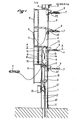
- the cable head for the optical cable shown in FIG. 1 comprises a trough 1, profiled in a U shape and secured at each of its ends to an angle iron 2,3.
- This chute is metallic, generally of aluminum, and has longitudinal grooves allowing the rapid fixing, by snap-fitting in particular, of various elements such as cassettes 4, drums 5, 6, beds 7 of "garters” (we call “garter” 9 an optical fiber which connects two cassettes), sheaths 8, etc.
- An optical cable 10, comprising a determined number of rods 12 (ten for example) serving as support for a determined number of optical fibers 13 (ten for example), enters the cable head from the top or from the base (case of Figures 1 and 5) of the chute 1, where it is fixed by fasteners 11.
- each rod 12 diverge above these fasteners and will feed one (or more) sheath (s) 8 and / or cassettes 4.
- each rod 12 is provided for feeding only one cassette 4.
- the chute 1 contains two drums 6, fixed either at the bottom of the chute itself, advantageously so that they can be translated ( embodiment shown in Figures 2 and 3), or to the side of the housing 23 of the cassettes 4 parallel to the bottom of the chute 1 (variant not shown).
- the drums 6 are intended to receive and store the excess supply rod. Indeed, as it is difficult to lengthen an optical fiber (and a fortiori a rod which comprises several) and we want to be able to freely change the connections in the same cable head, the rods are always over- sized.
- each rod 12 is therefore coiled over a part, -variable-, of its length around two drums 6 inside the chute 1 which thus ensures the function of protective enclosure.
- the end of each of them enters a cassette 4 where the optical fibers 13 which they carry are separated by an appropriate device 14 and then coiled over a certain length around two drums 15 before being connected each to a connector (or multiplexer) 16.
- each rod is coiled around two drums 6
- the second inside each cassette 4, where the fibers carried by each rod are detached from their support and coiled around two drums 15.
- the drums 6 and 15 are not identical, - the first are adjustable, not the seconds, but have in common that they are constituted by sectors of discs with an angle at most equal to about 90 ° and a radius approximately equal to the radius of curvature of the optical fibers.
- the drums 15, as it appears in FIG. 1, comprise four curved elements, of approximately 30 ° each, distributed regularly over a circumference. They are fixed inside the cassettes 4.
- the drums 6, when they are fixed to the bottom of the chute 1 (case of the embodiment shown in FIGS. 2 and 3), and not to the side of the housing 23 cassettes 4 parallel to the bottom of said chute (variant not shown) are movable at the bottom of chute 1.
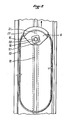
- FIG. 2 it can be seen that they consist of a disk sector 16, of angle at center equal to around 90 °, comprising a circular rim 17 to contain the layer or layers of rod windings 12.
- the thickness of these drums can reach 2/3 or even 3/4 of the length of the parallel uprights of the U-shaped section which constitutes the trough 1, which makes it possible to store a large length of rod knowing that usually the three sides of the U-shaped section are approximately equal and that the base of the U is expected to be slightly greater than twice the radius of curvature of the optical fibers (this in order to make installations as compact as possible).
- the drums 6 are made integral with the trough 1 by means of a screw 18 which passes through them right through, the head of which is retained in a median longitudinal groove 19, T-shaped, formed in the base of the metal profile and on the end of which is screwed a knob 20 which can be tightened and loosened by hand to fix the said drums on the chute 1 at the desired height.
- the drums 6 further comprise, projecting on their rear face, guide tabs 21 which penetrate into the groove 19 and prevent them from pivoting around the screws 18.
- the mobility of these drums, combined with their relatively large thickness compared to the section of rods 12 allows great flexibility and a large storage capacity.
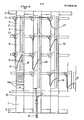
- FIG 3 which is a sectional view of the cable head of Figure 1 along the line AA, allows to appreciate the detail of the device at each cassette.
- the cassette 4 comprises a housing 23 snapped onto the chute 1 comprising two drums 15, around which the fibers 13 are coiled, and an orifice 24 for letting the rod 12 pass; a removable plate 25 on which the connectors or multiplexers 16 are fixed; a cover 26.
- the two upper cassettes are shown provided with their cover 26
- the chute 1 In cases where these boxes are longer than the standard size box shown in Figure 3, there is a piece acting as a spacer (called “spacer") between the chute 1 and the front drum 5 so that the radius of curvature of the fiber contained in the garter 9 is respected.
- the front drum 5 in fact comprises a portion of cylinder 27, of radius approximately equal to the radius of curvature of the optical fibers and intercepting an angle of approximately 120 °. So that the garters 9 do not undergo stresses exceeding their resistance to bending, it is important that the end of the circular part 27 is at a fixed distance from the connectors 16. Hence the need for a "spacer" when uses longer cassettes than standard cassettes.
- the particular devices are the front drums 5, which have been described above, the beds 7 of horizontal garters and the triple drums 22 which are advantageously arranged on the rear of the cable head (the beds 7 of garters horizontal as well as the triple drums 22 can nevertheless be arranged on the front of the garter head).
- FIG 4 a drum of this type: we see that it has two vertical walls 30 curved, and an oblique portion 31, also curved. The radius of curvature of these walls is approximately equal to that of the fibers.
- this drum has two guide fingers 32 intended to hold the garters in the bed 7, at the confluence of said drum and said bed.
- the triple drums 22 as well as the beds 7 which they adjoin are subject to the chutes 1 at each level of cassettes, below the upper connector 16.
- FIG. 5 Examples of garter paths are given in FIG. 5.
- the method used to establish the route of a garter 9 between two connectors 16 located on two different cable heads comprises the following steps: the jumper 9 is applied to the front drum 5; it is subject to it by means of a fastener 28 with automatic closure; the possible excess of the garter is made to make a loop along the base of the trough 1 on which said loop is maintained by means of a quick coupler 29; the garter is then made to follow an ascending path (this is always the case) to a triple drum 22: -this of the cassette from which it comes (starting cassette) if the cassette which it must reach (cassette arrival) is located at the same level as the departure cassette or at a lower level - that of the cassette, located on the same cable head as the departure cassette at the level of the arrival cassette, if the cassette d the arrival is located at a level higher than the level of the starting cassette; the garter is run in the bed 7, where the triple drum 22 determined above opens out, to the triple drum fixed to the cable head on which the arrival cassette is located; the
Landscapes
- Physics & Mathematics (AREA)
- General Physics & Mathematics (AREA)
- Optics & Photonics (AREA)
- Engineering & Computer Science (AREA)
- Computer Networks & Wireless Communication (AREA)
- Light Guides In General And Applications Therefor (AREA)
- Mechanical Coupling Of Light Guides (AREA)
Applications Claiming Priority (2)
| Application Number | Priority Date | Filing Date | Title |
|---|---|---|---|
| FR8419201A FR2575020B1 (fr) | 1984-12-14 | 1984-12-14 | Repartiteur pour cables optiques |
| FR8419201 | 1984-12-14 |
Publications (2)
| Publication Number | Publication Date |
|---|---|
| EP0186579A1 true EP0186579A1 (de) | 1986-07-02 |
| EP0186579B1 EP0186579B1 (en) | 1990-10-24 |
Family
ID=9310636
Family Applications (1)
| Application Number | Title | Priority Date | Filing Date |
|---|---|---|---|
| EP85402495A Expired EP0186579B1 (en) | 1984-12-14 | 1985-12-16 | Distribution frame for optical cables |
Country Status (4)
| Country | Link |
|---|---|
| US (1) | US4697874A (de) |
| EP (1) | EP0186579B1 (de) |
| JP (1) | JPS61145505A (de) |
| FR (1) | FR2575020B1 (de) |
Cited By (7)
| Publication number | Priority date | Publication date | Assignee | Title |
|---|---|---|---|---|
| FR2590371A1 (fr) * | 1985-11-18 | 1987-05-22 | Cit Alcatel | Chassis de tete de cables optiques |
| FR2622304A1 (fr) * | 1987-10-21 | 1989-04-28 | Telecommunications Sa | Dispositif d'integration de composants optoelectroniques et optiques et son application aux baies de brassage et de repartition |
| EP0623832A1 (de) * | 1993-05-05 | 1994-11-09 | KRONE Aktiengesellschaft | Kabelverteilergestell |
| FR2716540A1 (fr) * | 1994-02-23 | 1995-08-25 | Pouyet Henri | Tête de câble optique. |
| EP0640852A3 (de) * | 1993-08-30 | 1995-12-13 | At & T Corp | Verteilergestell und Ordnungsverfahren für optische Fasern. |
| EP1037081A1 (de) * | 1999-03-12 | 2000-09-20 | Siecor Operations, LLC | Faseroptische Vorratsvorrichtung |
| WO2019177934A1 (en) * | 2018-03-13 | 2019-09-19 | Corning Research & Development Corporation | Enclosure for local convergence point for fiber optic communications network |
Families Citing this family (64)
| Publication number | Priority date | Publication date | Assignee | Title |
|---|---|---|---|---|
| FR2598822B1 (fr) * | 1986-05-16 | 1988-08-26 | Telecommunications Sa | Equipement de repartition et raccordement de fibres optiques. |
| US4850901A (en) * | 1988-04-14 | 1989-07-25 | Brintec Corporation | Communications outlet |
| JPH0740966Y2 (ja) * | 1988-06-29 | 1995-09-20 | 四国電力株式会社 | 光ファイバ複合架空地線の余長収納器 |
| US4861134A (en) * | 1988-06-29 | 1989-08-29 | American Telephone And Telegraph Company, At&T Bell Laboratories | Opto-electronic and optical fiber interface arrangement |
| US4909583A (en) * | 1989-01-05 | 1990-03-20 | Hughes Aircraft Company | Method and apparatus for preserving modes in fiber optic connections requiring angular translation |
| US5396575A (en) * | 1992-12-18 | 1995-03-07 | Raynet Corporation | Sealed optical fiber closures |
| DE4336079C2 (de) * | 1993-10-22 | 1997-11-27 | Philips Patentverwaltung | Führungselement für Lichtwellenleiter |
| US5640482A (en) * | 1995-08-31 | 1997-06-17 | The Whitaker Corporation | Fiber optic cable management rack |
| US5915055A (en) * | 1997-06-30 | 1999-06-22 | Siecor Corporation | Method and apparatus for connectorizing fiber optic cable |
| US6024329A (en) * | 1997-11-10 | 2000-02-15 | Defem System Ab | Support device for a cableway |
| US5937131A (en) * | 1997-11-17 | 1999-08-10 | Adc Telecommunications, Inc. | Optical cable exit trough |
| JP2000009943A (ja) * | 1998-06-17 | 2000-01-14 | Fujitsu Ltd | 光伝送装置 |
| DE29922135U1 (de) | 1999-12-16 | 2000-02-17 | Quante Ag, 42109 Wuppertal | Schaltadermodul einer Glasfaser-Verteilereinrichtung sowie Glasfaser-Verteilereinrichtung mit Schaltadermodul |
| DE10255561A1 (de) * | 2002-11-22 | 2004-06-09 | Krone Gmbh | Verfahren und Vorrichtung zur Kopplung von Lichtwellenleitern |
| CN101923197A (zh) * | 2010-08-04 | 2010-12-22 | 南京华脉科技有限公司 | 光纤总配线架 |
| US9417418B2 (en) | 2011-09-12 | 2016-08-16 | Commscope Technologies Llc | Flexible lensed optical interconnect device for signal distribution |
| US9229172B2 (en) | 2011-09-12 | 2016-01-05 | Commscope Technologies Llc | Bend-limited flexible optical interconnect device for signal distribution |
| US9057859B2 (en) | 2011-10-07 | 2015-06-16 | Adc Telecommunications, Inc. | Slidable fiber optic connection module with cable slack management |
| RU2611105C2 (ru) | 2011-10-07 | 2017-02-21 | Адс Телекоммьюникейшнз, Инк. | Волоконно-оптическая кассета, система и способ |
| US9170391B2 (en) | 2011-10-07 | 2015-10-27 | Adc Telecommunications, Inc. | Slidable fiber optic connection module with cable slack management |
| US9002166B2 (en) | 2011-10-07 | 2015-04-07 | Adc Telecommunications, Inc. | Slidable fiber optic connection module with cable slack management |
| US9075203B2 (en) | 2012-01-17 | 2015-07-07 | Adc Telecommunications, Inc. | Fiber optic adapter block |
| US9195021B2 (en) | 2012-09-21 | 2015-11-24 | Adc Telecommunications, Inc. | Slidable fiber optic connection module with cable slack management |
| US10082636B2 (en) | 2012-09-21 | 2018-09-25 | Commscope Technologies Llc | Slidable fiber optic connection module with cable slack management |
| US9146374B2 (en) | 2012-09-28 | 2015-09-29 | Adc Telecommunications, Inc. | Rapid deployment packaging for optical fiber |
| US9488788B2 (en) | 2012-09-28 | 2016-11-08 | Commscope Technologies Llc | Fiber optic cassette |
| EP2901191A4 (de) | 2012-09-28 | 2016-10-26 | Tyco Electronics Ltd Uk | Herstellung und testen einer glasfaserkassette |
| US9223094B2 (en) | 2012-10-05 | 2015-12-29 | Tyco Electronics Nederland Bv | Flexible optical circuit, cassettes, and methods |
| NZ708968A (en) | 2013-01-29 | 2018-03-23 | CommScope Connectivity Belgium BVBA | Optical fiber distribution system |
| US9128262B2 (en) | 2013-02-05 | 2015-09-08 | Adc Telecommunications, Inc. | Slidable telecommunications tray with cable slack management |
| WO2014133943A1 (en) | 2013-02-27 | 2014-09-04 | Adc Telecommunications, Inc. | Slidable fiber optic connection module with cable slack management |
| US9435975B2 (en) | 2013-03-15 | 2016-09-06 | Commscope Technologies Llc | Modular high density telecommunications frame and chassis system |
| DK3531179T3 (da) | 2013-04-24 | 2021-03-01 | CommScope Connectivity Belgium BVBA | Optisk fiberfordelingssystem |
| CN105393151B (zh) | 2013-04-24 | 2018-09-18 | 泰科电子瑞侃有限公司 | 光导纤维分配系统 |
| US9851524B2 (en) | 2014-01-28 | 2017-12-26 | Commscope Technologies Llc | Slidable fiber optic connection module with cable slack management |
| US9494758B2 (en) | 2014-04-03 | 2016-11-15 | Commscope Technologies Llc | Fiber optic distribution system |
| CN104317020B (zh) * | 2014-10-11 | 2017-05-17 | 苏州速腾电子科技有限公司 | 通信光缆排线装置 |
| CN104317018B (zh) * | 2014-10-11 | 2017-05-17 | 苏州速腾电子科技有限公司 | 通信光缆大小分离装置及分离方法 |
| US9684143B2 (en) * | 2014-12-09 | 2017-06-20 | Commscope Technologies Llc | Releasable connection interface for a fiber optic component holder |
| WO2016094331A1 (en) | 2014-12-10 | 2016-06-16 | Commscope Technologies Llc | Fiber optic cable slack management module |
| US10261281B2 (en) | 2015-04-03 | 2019-04-16 | CommScope Connectivity Belgium BVBA | Telecommunications distribution elements |
| US10197757B2 (en) | 2015-05-15 | 2019-02-05 | Hubbell Incorporated | Cable storage wheels |
| US11674345B2 (en) | 2016-04-19 | 2023-06-13 | Commscope, Inc. Of North Carolina | Door assembly for a telecommunications chassis with a combination hinge structure |
| ES2851948T3 (es) | 2016-04-19 | 2021-09-09 | Commscope Inc North Carolina | Bastidor de telecomunicaciones con bandejas deslizables |
| WO2018046677A1 (en) | 2016-09-08 | 2018-03-15 | CommScope Connectivity Belgium BVBA | Telecommunications distribution elements |
| WO2018226959A1 (en) | 2017-06-07 | 2018-12-13 | Commscope Technologies Llc | Fiber optic adapter and cassette |
| MX2020002878A (es) | 2017-10-02 | 2020-07-22 | Commscope Technologies Llc | Circuito de fibra optica y metodo de preparacion. |
| US11385429B2 (en) | 2017-10-18 | 2022-07-12 | Commscope Technologies Llc | Fiber optic connection cassette |
| WO2019169148A1 (en) | 2018-02-28 | 2019-09-06 | Commscope Technologies Llc | Packaging assembly for telecommunications equipment |
| WO2019204317A1 (en) | 2018-04-16 | 2019-10-24 | Commscope Technologies Llc | Adapter structure |
| US11635578B2 (en) | 2018-04-17 | 2023-04-25 | CommScope Connectivity Belgium BVBA | Telecommunications distribution elements |
| US11320616B2 (en) | 2018-05-31 | 2022-05-03 | Hubbell Incorporated | Utility enclosures with cable storage systems |
| EP3844546A1 (de) | 2018-08-31 | 2021-07-07 | CommScope Connectivity Belgium BVBA | Rahmenanordnungen für optische faserverteilungselemente |
| WO2020043909A1 (en) | 2018-08-31 | 2020-03-05 | CommScope Connectivity Belgium BVBA | Frame assemblies for optical fiber distribution elements |
| EP3844973B1 (de) | 2018-08-31 | 2024-11-06 | CommScope Connectivity Belgium BVBA | Rahmenanordnungen für optische faserverteilungselemente |
| WO2020043911A1 (en) | 2018-08-31 | 2020-03-05 | CommScope Connectivity Belgium BVBA | Frame assemblies for optical fiber distribution elements |
| DK3844972T3 (da) | 2018-08-31 | 2022-10-17 | CommScope Connectivity Belgium BVBA | Rammesamlinger til optiske fiberfordelingselementer |
| EP3871028B1 (de) | 2018-10-23 | 2025-06-18 | CommScope Connectivity Belgium BVBA | Rahmenanordnungen für optische faserverteilungselemente |
| US11947177B2 (en) | 2019-01-25 | 2024-04-02 | CommScope Connectivity Belgium BVBA | Frame assemblies for optical fiber distribution elements |
| US12174443B2 (en) | 2020-01-22 | 2024-12-24 | CommScope Connectivity Belgium BVBA | Cable termination units for optical fiber distribution elements |
| EP4094108B1 (de) | 2020-01-24 | 2025-06-18 | CommScope Connectivity Belgium BVBA | Telekommunikationsverteilungselemente |
| US12468106B2 (en) | 2020-02-07 | 2025-11-11 | CommScope Connectivity Belgium BVBA | Telecommunications module arrangements |
| US12339511B2 (en) | 2020-03-31 | 2025-06-24 | Commscope Technologies Llc | Fiber optic cable management systems and methods |
| CN112103076B (zh) * | 2020-09-27 | 2022-05-13 | 昆山联滔电子有限公司 | 一种从电磁感应线圈中分离功能性线缆的分线装置 |
Citations (3)
| Publication number | Priority date | Publication date | Assignee | Title |
|---|---|---|---|---|
| FR2531576A1 (fr) * | 1982-08-04 | 1984-02-10 | Cit Alcatel | Bati de raccordement et d'interface opto-electronique |
| EP0101970A1 (de) * | 1982-08-04 | 1984-03-07 | Alcatel | Anschlussstück eines faseroptischen Kabels |
| EP0116480A1 (de) * | 1983-01-05 | 1984-08-22 | SAT (Société Anonyme de Télécommunications),Société Anonyme | Gehäuse zum Verbinden und Mischen optischer Fasern |
-
1984
- 1984-12-14 FR FR8419201A patent/FR2575020B1/fr not_active Expired
-
1985
- 1985-12-13 JP JP60280856A patent/JPS61145505A/ja active Pending
- 1985-12-13 US US06/808,806 patent/US4697874A/en not_active Expired - Fee Related
- 1985-12-16 EP EP85402495A patent/EP0186579B1/fr not_active Expired
Patent Citations (3)
| Publication number | Priority date | Publication date | Assignee | Title |
|---|---|---|---|---|
| FR2531576A1 (fr) * | 1982-08-04 | 1984-02-10 | Cit Alcatel | Bati de raccordement et d'interface opto-electronique |
| EP0101970A1 (de) * | 1982-08-04 | 1984-03-07 | Alcatel | Anschlussstück eines faseroptischen Kabels |
| EP0116480A1 (de) * | 1983-01-05 | 1984-08-22 | SAT (Société Anonyme de Télécommunications),Société Anonyme | Gehäuse zum Verbinden und Mischen optischer Fasern |
Cited By (10)
| Publication number | Priority date | Publication date | Assignee | Title |
|---|---|---|---|---|
| FR2590371A1 (fr) * | 1985-11-18 | 1987-05-22 | Cit Alcatel | Chassis de tete de cables optiques |
| EP0226805A1 (de) * | 1985-11-18 | 1987-07-01 | Alcatel Cit | Verteilergestell für Glasfaserkabelenden |
| US4752110A (en) * | 1985-11-18 | 1988-06-21 | Alcatel | Cabinet for an optical cable head |
| FR2622304A1 (fr) * | 1987-10-21 | 1989-04-28 | Telecommunications Sa | Dispositif d'integration de composants optoelectroniques et optiques et son application aux baies de brassage et de repartition |
| EP0623832A1 (de) * | 1993-05-05 | 1994-11-09 | KRONE Aktiengesellschaft | Kabelverteilergestell |
| EP0640852A3 (de) * | 1993-08-30 | 1995-12-13 | At & T Corp | Verteilergestell und Ordnungsverfahren für optische Fasern. |
| FR2716540A1 (fr) * | 1994-02-23 | 1995-08-25 | Pouyet Henri | Tête de câble optique. |
| EP0669544A1 (de) * | 1994-02-23 | 1995-08-30 | Societe Henri Pouyet | Anschlussstück eines faseroptischen Kabels |
| EP1037081A1 (de) * | 1999-03-12 | 2000-09-20 | Siecor Operations, LLC | Faseroptische Vorratsvorrichtung |
| WO2019177934A1 (en) * | 2018-03-13 | 2019-09-19 | Corning Research & Development Corporation | Enclosure for local convergence point for fiber optic communications network |
Also Published As
| Publication number | Publication date |
|---|---|
| US4697874A (en) | 1987-10-06 |
| JPS61145505A (ja) | 1986-07-03 |
| FR2575020A1 (fr) | 1986-06-20 |
| FR2575020B1 (fr) | 1987-02-13 |
| EP0186579B1 (en) | 1990-10-24 |
Similar Documents
| Publication | Publication Date | Title |
|---|---|---|
| FR2575020A1 (fr) | Repartiteur pour cables optiques | |
| EP0220969A1 (de) | Anordnung für optische Verbindungen | |
| EP0348278A1 (de) | Verteil- und Verbindungsvorrichtung für optische Fasern | |
| EP0116480B1 (de) | Gehäuse zum Verbinden und Mischen optischer Fasern | |
| EP0185923B1 (de) | Träger für optische Faserverbindungen | |
| EP0538164A1 (de) | Verteilergestell für optische Kabel hoher Kapazität | |
| US7613377B2 (en) | Hinge for fiber optic categorization and management tray | |
| EP0550327B1 (de) | Stütz- und Führungsgerüst für elektrische und optische Übertragungskabeln | |
| FR2663917A1 (fr) | Dispositif modulaire pour le stockage de reserves de support de transmission sur des liaisons, notamment a fibre optique. | |
| FR2590371A1 (fr) | Chassis de tete de cables optiques | |
| FR2832226A1 (fr) | Module de distribution et de connexion de fibres optiques destine a un repartiteur optique | |
| FR2556895A1 (fr) | Dispositif de raccordement de cables, notamment a fibres optiques | |
| US12259590B2 (en) | Fiber-optic apparatus | |
| US12353040B2 (en) | Adapter configured to permit a heat shrink splice holder portion of a fiber splice cassette to hold a mechanical crimp splice protector | |
| US20250231365A1 (en) | Fiber-optic splice storage tray | |
| EP1054279A1 (de) | Zugangsmuffe für ein oder mehrere optische Fasern in einem gespannten Kabel | |
| FR2458970A1 (fr) | Reseau de commutation a structure repartie pour centre de telecommunications | |
| EP0660477A1 (de) | Wandverbindungsdose für eine optische Gebäudeverkabelung | |
| CA1124824A (fr) | Dispositif de raccordement des batis aux repartiteurs dans les centrales de telecommunication | |
| EP1368687A2 (de) | Faseroptische durchfürung und gehäuse für optische bauelemente mit einer solchen durchfürung | |
| FR2694642A1 (fr) | Dispositif de raccordement d'au moins un câble de transmission à des équipements électroniques. | |
| EP4024109A1 (de) | Optischer anschlusskasten | |
| US12578542B2 (en) | Fiber optic component holder having a variably sized receiving portion for holding various sizes of fiber optical components or multiple fiber optical components | |
| FR2743899A1 (fr) | Dispositif d'organisation de raccordements de fibres optiques | |
| FR3108708A1 (fr) | Boitier optique comprenant un élément de stockage pour fibres optiques |
Legal Events
| Date | Code | Title | Description |
|---|---|---|---|
| PUAI | Public reference made under article 153(3) epc to a published international application that has entered the european phase |
Free format text: ORIGINAL CODE: 0009012 |
|
| AK | Designated contracting states |
Kind code of ref document: A1 Designated state(s): BE DE FR GB IT NL SE |
|
| 17P | Request for examination filed |
Effective date: 19870225 |
|
| 17Q | First examination report despatched |
Effective date: 19880907 |
|
| GRAA | (expected) grant |
Free format text: ORIGINAL CODE: 0009210 |
|
| PUAB | Information related to the publication of an a document modified or deleted |
Free format text: ORIGINAL CODE: 0009199EPPU |
|
| PUAC | Information related to the publication of a b1 document modified or deleted |
Free format text: ORIGINAL CODE: 0009299EPPU |
|
| AK | Designated contracting states |
Kind code of ref document: B1 Designated state(s): BE DE FR GB IT NL SE |
|
| STAA | Information on the status of an ep patent application or granted ep patent |
Free format text: STATUS: THE APPLICATION IS DEEMED TO BE WITHDRAWN |
|
| DB1 | Publication of patent cancelled | ||
| RA1 | Application published (corrected) |
Date of ref document: 19860702 Kind code of ref document: A1 |
|
| 18D | Application deemed to be withdrawn |
Effective date: 19900605 |
|
| NLXE | Nl: other communications concerning ep-patents (part 3 heading xe) |
Free format text: IN PAT.BUL.23/90,PATENTNUMBER 0186579 SHOULD BE DELETED |
|
| BERE | Be: lapsed |
Owner name: NOZICK JACQUES E. Effective date: 19901231 |