EP0187192B1 - Verfahren und Vorrichtung zum Rapportieren von Mehrfarbenoffsetdruckmaschinen - Google Patents
Verfahren und Vorrichtung zum Rapportieren von Mehrfarbenoffsetdruckmaschinen Download PDFInfo
- Publication number
- EP0187192B1 EP0187192B1 EP85109421A EP85109421A EP0187192B1 EP 0187192 B1 EP0187192 B1 EP 0187192B1 EP 85109421 A EP85109421 A EP 85109421A EP 85109421 A EP85109421 A EP 85109421A EP 0187192 B1 EP0187192 B1 EP 0187192B1
- Authority
- EP
- European Patent Office
- Prior art keywords
- unit
- printing
- circumferential
- printing plate
- couple
- Prior art date
- Legal status (The legal status is an assumption and is not a legal conclusion. Google has not performed a legal analysis and makes no representation as to the accuracy of the status listed.)
- Expired
Links
- 238000000034 method Methods 0.000 title claims description 22
- 238000007645 offset printing Methods 0.000 title claims description 18
- 238000007639 printing Methods 0.000 claims description 275
- 230000000694 effects Effects 0.000 claims description 28
- 238000006073 displacement reaction Methods 0.000 claims description 25
- 230000008859 change Effects 0.000 claims description 23
- RDYMFSUJUZBWLH-UHFFFAOYSA-N endosulfan Chemical compound C12COS(=O)OCC2C2(Cl)C(Cl)=C(Cl)C1(Cl)C2(Cl)Cl RDYMFSUJUZBWLH-UHFFFAOYSA-N 0.000 claims description 23
- 238000012544 monitoring process Methods 0.000 claims description 9
- 230000009471 action Effects 0.000 description 4
- 230000000712 assembly Effects 0.000 description 4
- 238000000429 assembly Methods 0.000 description 4
- 230000004048 modification Effects 0.000 description 2
- 238000012986 modification Methods 0.000 description 2
- XLYOFNOQVPJJNP-UHFFFAOYSA-N water Substances O XLYOFNOQVPJJNP-UHFFFAOYSA-N 0.000 description 2
- 230000004075 alteration Effects 0.000 description 1
- 239000003086 colorant Substances 0.000 description 1
- 230000008878 coupling Effects 0.000 description 1
- 238000010168 coupling process Methods 0.000 description 1
- 238000005859 coupling reaction Methods 0.000 description 1
- 238000010586 diagram Methods 0.000 description 1
- 230000009977 dual effect Effects 0.000 description 1
- 230000002093 peripheral effect Effects 0.000 description 1
- 230000008569 process Effects 0.000 description 1
- 230000000979 retarding effect Effects 0.000 description 1
- 230000001360 synchronised effect Effects 0.000 description 1
Images



Classifications
-
- B—PERFORMING OPERATIONS; TRANSPORTING
- B41—PRINTING; LINING MACHINES; TYPEWRITERS; STAMPS
- B41F—PRINTING MACHINES OR PRESSES
- B41F13/00—Common details of rotary presses or machines
- B41F13/08—Cylinders
- B41F13/10—Forme cylinders
- B41F13/12—Registering devices
- B41F13/14—Registering devices with means for displacing the cylinders
Definitions
- the present invention refers to a method for registering a perfecting offset printing unit to a reference perfecting offset printing unit while minimizing displacement between associated non-print gap areas according to the preamble of claim 1. Further, the present invention refers to an apparatus for registering a perfecting offset printing unit to a reference perfecting offset printing unit while minimizing displacement between associated non-print gap areas according to the preamble of claim 12.
- Multi-unit printing presses that print color images superimposed upon each other to form a complete multi-color image are known in the art. To form a clear multi-color image, it is necessary to have precise registration between the various units of the printing press.
- a multi-unit printing method and press comprising at least two plate cylinders cooperating each with an inking system.
- the plates are offset to each other such that a web may be printed continuously.
- the printing press may also be used for normal printing whereby blank portions remain between the printed images, means are provided to effect circumferential register adjustment.
- the print starting lines of the two plate cylinders coincide with each other, and in a second position, the print starting lines are offset to each other. No specific methods or means are disclosed for registering a perfecting offset printing unit to a reference unit.
- a web printing press comprising a plurality of printing units, at least one of the printing units being adapted to be in a printing mode while at least one other of said printing units is in a non-printing mode when said press is in use.
- a separate drive motor is associated with each of said printing units, and a common drive shaft extending through said printing units is provided.
- Respective drive means for transmitting torque from each of said drive motors to the printing unit associated therewith and to said common drive shaft include a clutch in each of said drive means arranged between said common drive shaft and its respective motor.
- said drive motor may be selectively engaged with said common drive shaft for driving all printing units and selectively disengaged from said common drive shaft for driving only the printing unit with which said motor is associated. Again, no means are disclosed for registering a perfecting offset printing unit to a reference unit.
- Partial registration can be accomplished by utilizing a unit-to-unit phaser adjustment assembly to change the printing phase of an upper and lower printing couple of one unit to that of another unit. Also, partial registration can be accomplished within each printing unit by utilizing an upper and lower circumferential adjustment assembly to rotate the upper and lower plate cylinders with respect to their associated blanket cylinders.
- the printing press is made ready for a printing run by setting each of the printing units to a mechanical zero position.
- an operator will examine the final printed image and will adjust the press, unit-by-unit, to register the image printed by one unit to that printed by another unit until all the units are in register.
- further adjustments are made by the operator. These adjustments are necessitated by variances in paper properties, the amount of ink being applied to the paper, the amount of water applied to the paper, the amount of web tension and web elasticity.
- the operator makes unit-to-unit adjustments or circumferential adjustments within a unit, he must stop the press and mechanically advance or retard the cylinders or unit drive gears.
- a new and improved method and apparatus for registering a perfecting offset printing unit to a reference perfecting offset printing unit while minimizing displacement between associated non-print gap areas is provided.
- the new method and apparatus is designed to make large registration changes needed utilizing the unit-to-unit phase while employing the circumferential adjustment assembly to make only the within unit changes necessary to complete the registration.
- a reference unit is first calibrated to an initial zero position.
- a unit to be registered to the reference unit is then calibrated.
- the position of the upper and lower printing plate in the unit to be registered is monitored. As the web is run through the units, the print registration is monitored and upper and lower circumferential changes needed to effect registration are inputted to a control device.
- the control device determines a circumferential bias responsive to the determined printing position change needed to effect registration and responsive to the monitored circumferential position of the upper and lower printing plates. Rotation of the printing couples of the unit to be registered and rotation of the upper and lower printing plates within the unit to be registered are made simultaneous while the press continues to run. These simultaneous rotations responsive to the determined circumferential bias and responsive to the monitored printing plate positions and the determined printing position changes needed effects registration of the one unit to the reference unit.
- the apparatus for registering a perfecting offset printing unit to a reference perfecting offset printing unit while minimizing displacement between associated non-print gap areas both printing units acting in succession on a web and each unit having an upper printing plate disposed around an upper print cylinder and an upper blanket disposed around an upper blanket cylinder, such combination defining an upper printing couple and each unit having a lower printing plate disposed around a lower print cylinder and a lower blanket disposed around a lower blanket cylinder, such combination defining a lower printing couple, is characterized by the characteristics defined in claim 12.
- the circumferential displacement U, of the upper printing plate of the unit with respect to its associated upper blanket is determined.
- the circumferential displacement L, of the lower printing plate of the unit with respect to its associated lower blanket is determined.
- the print registration between the unit and the reference unit is monitored and a AU and a AL changes needed to effect registration of the unit with the reference unit are determined where ⁇ U is the amount of shift needed to register the upper printing couple of the unit with the upper printing couple of the reference unit and where AL is the amount of shift needed to register the bottom printing couple of the unit with the bottom printing couple of the reference unit.
- the circumferential bias B is determined according to the equations:
- the upper printing couple and the lower printing couple are rotated utilizing the unit-to-unit phaser adjustment assembly by an amount sufficient to effect a circumferential displacement from the reference unit equal to the bias B.
- the upper plate of the unit is rotated by an amount U 2 sufficient to effect the circumferential displacement equal to U 1 + ⁇ U-B.
- the loewr plate of the unit is rotated by an amount L 2 sufficient to effect a circumferential displacement equal to L 1 + ⁇ L-B.
- Another feature of the present invention is the provision of adding or subtracting a value k equal to to the bias equation for determining B. Adding or subtracting k provides that misregistration within a unit is equally shared by the upper and lower printing plates, hence reducing blanket gap to plate gap misalignment by one half.
- each printing unit includes an upper printing couple 20 having an upper printing plate disposed around an upper printing cylinder 22 and an upper blanket disposed around an upper blanket cylinder 24.
- Each unit also includes a lower printing couple 26 having a lower blanket disposed around a lower blanket cylinder 28 and a lower printing plate disposed around a lower printing cylinder 30.
- a common drive shaft 32 having an axis of rotation 33 is operatively connected to each upper blanket cylinder of each printing unit and is adapted to drive the upper and lower printing couples in each printing unit.
- a web 34 is fed into the printing press 10 and is acted on in succession by the upper and lower printing couples of each printing unit.
- One of the units in the printing press is designed as a reference unit which is printing unit 16 of Figure 1.
- Printing unit 16 is calibrated into a make-ready condition, meaning that the upper and lower blanket gaps align and the upper and lower printing plate gaps align with their associated blanket gaps.
- All other units in the printing press 10 include a unit-to-unit phaser adjustment assembly 36 operatively connected to the upper blanket cylinder 24, an upper circumferential adjustment assembly 38 operatively connected to the upper printing cylinder 22 in a printing unit and a lower circumferential adjustment assembly 40 operatively connected to the lower printing cylinder 30 of the printing unit.
- a control 42 is provided and is operatively connected to each unit-to-unit phaser adjustment assembly, upper circumferential adjustment assembly and lower circumferential adjustment assembly for the three printing units 12, 14 and 18 of in the printing press 10.
- print registration is monitored either by an operator or by means of electronic sensing devices. If the printing press 10 is in complete registration, meaning that all the printing units are registered, changes in humidity, elastic properties of the web, amount ofjnk applied to the printing units, the amounts of water applied, amount of web tension and web elasticity can cause the printing between units to become misregistered. Changes needed to register a particular printing unit to the other printing units is inputted to the control 42 such as a computer. The control 42 will control the unit-to-unit phaser adjustment assembly and the upper and lower circumferential adjustment assemblies in a misregistered unit to effectuate registration.
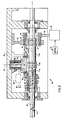
- a helical gear 44 having an externally threaded, projecting sleeve portion 46 encircles drive shaft 32 concentric with the drive shaft axis 33 and is threaded in a fixed mounting bracket 48 having a cooperatively threaded receiving bore 49.
- a worm gear 50 projects from a motor shaft 52 rotatably mounted to a motor 54. Worm gear 50 is drivingly meshed with helical gear 44.
- the control 42 is operatively connected to the motor 54 for control thereof.
- the motor 54 is a dual direction motor so that shaft 52 can rotate in either direction.
- worm gear 50 drives the helical gear 44.
- the threaded engagement between the threaded projecting sleeve portion 46 and the fixed mounting bracket 48 causes the helical gear with its threaded projecting sleeve portion to move longitudinally along the drive shaft 32 in either direction depending on the direction of rotation of the shaft 52.
- a drive tube 56 is mounted coaxial with the drive shaft 32.
- a thrust bearing 58 is disposed between an interior recess portion 60 of the threaded projecting sleeve portion 46 and radially projecting collar portions 62, 64 of the drive tube 56.
- a second drive tube 66 is coupled to the drive tube 56 by means of a coupling 68.
- the second drive tube 66 is mounted coaxially with the drive shaft 32.
- Drive shaft 32 has longitudinally straight splines 70 that mate with internal straight splines 72 of the second drive tube 66.
- the second drive tube 66 can slide longitudinally along the drive shaft 32 because of the straight spline arrangement 70, 72. Rotational motion of the drive shaft 32 will cause rotational motion of the second drive shaft 66 and in turn rotational motion of the drive tube 56. Rotational motion of the drive shaft 56 will not affect the drive gear 44 because of the thrust bearing 58.
- a bevel gear 74 having internal helical splines 76 is radially disposed around second drive tube 66 and mesh with helically projecting splines 78 of the second drive tube 66.
- the bevel gear 74 is longitudinally fixed at both ends in a suitable fashion with respect to the drive shaft 32.
- the helically projecting splines 78 cam against the internal helical splines 76 of the bevel gear 74.
- the camming action between the helical gears causes rotational motion of the bevel gear 74.
- the particular gear arrangement between the drive shaft 32, the second drive tube 66 and the bevel gear 74 also couples the bevel gear 74 to the drive shaft 32 such that rotational motion of the drive shaft 32 also rotates the bevel gear 74. Therefore, the bevel gear 74 can be rotated either by rotation of the drive shaft 32 or longitudinal motion of the second drive tube 66. Since the second drive tube 66 can move longitudinally in either direction, the bevel gear 74 can be rotated also in either direction in cooperation with the longitudinal motion of the second drive tube 66.
- Bevel gear 74 is meshed with a spiral bevel gear 80.
- Spiral gear 80 is rotatably fixed to a frame 82 for rotation about an axis 84.
- the spiral gear 80 has a drive gear 86 fixed thereto and rotatable about the axis 84.
- the drive gear 86 is meshed with the drive gear 88 for the upper blanket cylinder 24 for the associated printing unit.
- drive gear 88 of the upper blanket cylinder 24 is geared to the drive gear 90 for the upper plate cylinder 22 and to the drive gear 92 for the lower blanket cylinder 28.
- Drive gear 92 is geared with a drive gear 94 for the lower plate cylinder 30.
- Rotation of the drive gear 88 causes simultaneous rotation of the drive gears 90, 92 and 94, and, in turn rotation of the cylinders 22, 24, 28 and 30. It will be appreciated that rotation of the drive shaft 32 will drive all of the cylinders in a printing unit.
- the unit-to-unit phaser adjustment assembly 36 can be utilized through control 42 to change the phase of a printing unit with respect to another printing unit by rotating all the cylinders in the unit being adjusted without causing rotation of the drive shaft 32.
- a print unit 16 is an initial reference print unit, i.e., the blanket and print cylinders are mechanically set to a zero position with all the printing plate and blanket gaps aligned.
- Another printing unit can be adjusted with respect to the reference unit by utilizing the unit-to-unit phaser adjustment assembly 36.
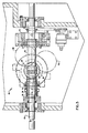
- FIG. 5 the operation of a circumferential adjustment assembly for a given printing unit will be appreciated.
- the circumferential adjustment assemblies for each printing unit is similar in structure. Therefore, for simplicity, only one such unit will be discussed in detail.
- An upper circumferential adjustment assembly 38 is shown with the drive gear 88 meshed with the drive gear 90.
- a circumferential adjustment assembly is described in U.S. Patent No. 3,945,266 to Dufour et al., which is assigned to the assignee of this application, and is fully incorporated herein by reference.
- the upper circumferential adjustment assembly 38 includes a pair of helical gears 96, 98 mounted coaxially with the upper printing plate cylinder 22.
- the helical gear 98 is fixedly mounted on a spindle 100 of the upper printing cylinder 22 so as to rotate with the cylinder 22.
- the helical gear 98 has helical gear teeth mounted on the left end thereof which mesh with the helical gear teeth of the gear 96.
- Gear 98 also has a projecting sleeve portion 102 which is keyed by a suitable key 104 for rotation with the spindle 100.
- the gear 98 is fixed against axial movement of the spindle 100 between a shoulder 106 on the spindle and a cap 108 suitably secured to the end of the spindle 100 and which also engages an internal shoulder 110 of the gear sleeve portion 102.
- a slight gap can exist between the cap 108 and the end of the spindle 100 in order that the gear 98 be securely held in position.
- the spindle 100 of the cylinder is supported for rotation in a suitable bearing arrangement 112 in a housing member 114.
- the left side of the cylinder 22 has a spindle and bearing mounting (not shown) to support the other end of cylinder 22 for rotation about a central axis.
- the cylinder 22 is driven for the purposes of printing through the main drive gear 90 which is suitably secured to the gear member 96 by means of a plurality of bolts 116.
- the drive to the cylinder 22 during printing is through the gear 90, the meshing helical teeth of gears 96, 98, through the key 104, to the spindle 100.
- the outer peripheral gear teeth on the gear 90 are spur gear teeth, that is, the gear teeth extend parallel to the axis of rotation of the gear.
- Circumferential adjustment of the cylinder 22 occurs upon relative axial movement of the gears 96, 98.
- the meshing helical teeth of the gears 96, 98 cause the camming action to occur which results in circumferential movement of the cylinder 22.
- the gear 96 is moved axially relative to the gear 98 to effect this camming action.
- the gear 90 likewise is moved axially, but since the teeth thereon are spur gear teeth, the gear 90 is free to move axially relative to its meshing drive gear 88. Also, due to the meshing engagement of the teeth of the gear 90 with its meshing gear 88 and the resistance which this creates to rotation of the gear 96.
- a gear 98 will be cammed and rotate.
- the gear 96 is moved axially for the purpose of circumferential adjustment of the cylinder 22 by energization of a motor, Figure 6.
- the motor is coupled through a drive chain (not shown) to a spindle 118.
- Spindle 118 is connected to a drive shaft 120.
- the drive shaft 120 is threadedly engaged at 122 in a threaded bore 124 in a bracket member 126.
- the bracket member 126 has a bearing 128 interposed between the outer periphery of the bracket 126 and a projecting sleeve portion 130 of the gear 96.
- the bearing 128 is trapped against axial movement relative to the bracket 126, as well as trapped against axial movement relative to the sleeve portion 130 of the gear 96. This trapping is effective by means of suitable shoulders, a cap and a retaining ring.
- the leftwardmost end of the shaft 120 is supported by a bearing 132 which is located intermediate the sleeve portion 102 of the helical gear 98 and the outer end of the drive shaft 120.
- the bearing 132 is suitably supported so as not to move axially relative to either the drive shaft 120 or the sleeve portion 102 of the gear 98.
- the drive shaft 120 is rotated.
- the drive shaft 120 cannot move axially due to the fact that the drive shaft 120 is fixed at its left end, in effect, to the cylinder 22 which holds it from axial movement.
- the bracket member 126 will move axially relative to the drive shaft 120 in a direction indicated by arrows 134.
- the bracket member 126 when it is moved axially, forces the gear 96, axially relative to the gear 98, and as the gear 96 moves axially relative to the gear 96, the aforementioned camming action between the gear teeth of the gears 96, 98 occurs and the cylinder 22 is moved circumferentially.
- a rod 136 is provided which extends through an opening 138 of the bracket member 126, and the rod 136 guides the axial movement of these parts and prevents rotation of the bracket 126 about the drive shaft 120.
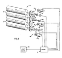
- Control unit 42 is operatively connected to the motor 54 of the unit-to-unit phaser adjustment assembly 36.
- the control 42 is also operatively connected to a motor 140 of the upper circumferential adjustment assembly 38 and to a motor 142 of the lower circumferential adjustment assembly 40.
- a potentiometer 144 is operatively connected to the upper printing cylinder 22 and is utilized to monitor rotational position of the upper printing cylinder 22 and in turn the upper printing plate disposed therearound.
- a potentiometer 146 is operatively connected to the upper blanket cylinder 24 and is utilized to monitor the rotational phase position of the printing unit 14.
- a potentiometer 148 is operatively connected to the lower printing cylinder 30 and is utilized to monitor the rotational position of the lower printing cylinder 30 and in turn the lower printing plate disposed therearound.
- the potentiometers 144, 146 and 148 are operatively connected to the control 42.
- the drive shaft 32 is not shown in Figure 6, but it will be appreciated, as described above, that the drive shaft 32 drives the print unit 14 through driving gear 86.
- the unit-to-unit phaser adjustment 36 is utilized to adjust the phase of the print unit 14 to a reference printing unit 16.
- the upper circumferential adjustment assembly 38 is utilized to adjust the circumferential displacement between the upper printing plate and the upper blanket.
- the lower circumferential adjustment assembly 40 is utilized to adjust the relative circumferential position of the lower printing plate to the lower blanket.
- a flow chart is shown of the logic steps made by the controller 42 to register the printing unit 14 with the reference printing unit 16.
- Each of the printing units are registered according to the same method. For simplicity, only registration of printing unit 14 is described in detail.
- U i Any circumferential displacement between the gaps in the upper printing plate and its associated upper blanket
- L 1 any displacement between the gaps of the lower printing plate and its associated lower blanket
- the upper blanket and lower blankets are set such that their gaps align with each other.
- the point of contact on web 34 of the upper and lower blanket gaps of the printing unit 14 and the point of contact on web 34 of the upper and lower blanket gaps of the reference unit 16 may have an amount of offset defined as P i . If the point of contact of the blanket gaps for the two units coincide, P 1 would equal zero.
- step 160 The initials U i , L, and P, of printing unit 14 are inputted in step 160 to the controller 42.
- Step 162 monitors the print registration between the printing unit 14 and the reference printing unit 16.
- step 164 the determination is made whether or not the units are still in registration based on the monitoring of step 164, i.e., the image printed by the printing unit 14 exactly coincides with the printing image printed by the printing unit 16 on the web 34. If no registration change is needed, step 162 is returned to and monitoring of the print registration continues. If a registration change is needed, step 166 determines the amount AU of circumferential change needed to register the upper printing couple of the printing unit 14 with the upper printing couple of the reference printing unit 16.
- Step 168 determines if the absolute value of U, +AU is less than or equal to the absolute value of L1+LlL.
- a bias B is calculated depending on the results of step 168. If the result of step 168 is yes, then, a bias B is determined in step 170 to equal If the result of step 168 is no, then, the bias B determined in step 172 according to the equation
- the unit-to-unit phaser adjustment assembly 36, the upper circumferential adjustment assembly 38 and the lower circumferential adjustment assembly 40 rotates the cylinders in step 174 responsive to the equations provided therein.
- the unit-to-unit phaser adjustment assembly will alter the present offset P, by an amount P 2 equal to the bias B.
- the new position of the upper and lower printing couple phase of printing unit 14 with respect to the reference printing unit 16 is equal to P 1 +B.
- B may be a negative number.
- a positive B represents an advance of the printing unit-to-unit phase and a negative number represents the retarding of the printing unit-to-unit phase.
- the upper circumferential adjustment assembly 38 rotates the upper printing plate by rotating the upper printing plate cylinder 22 by an amount U 2 which is equal to U 1 + ⁇ U-B.
- step 176 the U, and L, on the left side of the equation are the new value of U 1 and L 1 and the U 1 and L 1 on the right side of the equation are the old U 1 and L, values used in the calculations in steps 168,170,172 and 174.
- step 162 is repeated to continue monitoring of the print registration. If a registration change is needed in step 164, a new AU and AL is determined in step 166 and the calculations in steps 168, 170, 172 and 174 are made utilizing the updated U, and L 1 values and the new AU and AL values determined in step 166.
- the unit-to-unit phaser adjustment assembly is utilized to perform a major part of the change to effect registration between units while the upper and lower circumferential adjustment assemblies are utilized to make the remainder of the changes within the printing unit being adjusted. It is possible in the bias equations to let be equal to k.
- step 168 If the answer in step 168 were yes, when U 2 in step 174 would be equal to 0. Thus, L 2 for the lower circumferential adjustment assembly would be the only one adjusted for registration. Similarly, if the determination in step 168 was no, then L 2 in step 174 would be equal to 0 and U 2 would be the only circumferential change made.
- the initial U i , L 1 and P 1 positions inputted in step 160 are determined by the potentiometers 144, 148 and 146, respectively. It is possible to determine the cylinder position by counting pulses given to the motors by the controller 42. It is preferable that motors 54, 140 and 142 are synchronous motors. Knowing that the motor shaft rotates through a specific angle for a given number of pulses, the positions of the cylinders can be calculated from an initial known position. It is also possible to have mechanical zero indicators that will produce a signal when the cylinder is rotated to a position tripping the zero indicator. Motor pulses can be counted after a zero indication is received and thereby determine the cylinder positions.
Landscapes
- Engineering & Computer Science (AREA)
- Mechanical Engineering (AREA)
- Inking, Control Or Cleaning Of Printing Machines (AREA)
Claims (18)


Applications Claiming Priority (2)
| Application Number | Priority Date | Filing Date | Title |
|---|---|---|---|
| US671415 | 1984-11-14 | ||
| US06/671,415 US4572074A (en) | 1984-11-14 | 1984-11-14 | Multi-unit press register |
Publications (2)
| Publication Number | Publication Date |
|---|---|
| EP0187192A1 EP0187192A1 (de) | 1986-07-16 |
| EP0187192B1 true EP0187192B1 (de) | 1990-05-23 |
Family
ID=24694429
Family Applications (1)
| Application Number | Title | Priority Date | Filing Date |
|---|---|---|---|
| EP85109421A Expired EP0187192B1 (de) | 1984-11-14 | 1985-07-26 | Verfahren und Vorrichtung zum Rapportieren von Mehrfarbenoffsetdruckmaschinen |
Country Status (3)
| Country | Link |
|---|---|
| US (1) | US4572074A (de) |
| EP (1) | EP0187192B1 (de) |
| DE (1) | DE3577823D1 (de) |
Families Citing this family (15)
| Publication number | Priority date | Publication date | Assignee | Title |
|---|---|---|---|---|
| US4685394A (en) * | 1986-02-20 | 1987-08-11 | Molins Machine Company | Phase register control for printer-slotter machine |
| DE3712702A1 (de) * | 1987-04-14 | 1988-11-03 | Roland Man Druckmasch | Registerstellvorrichtung |
| US4879950A (en) * | 1987-06-19 | 1989-11-14 | Ryobi Ltd. | Image position adjusting apparatus of rotary press machine |
| US4836112A (en) * | 1988-02-19 | 1989-06-06 | Rockwell International Corporation | Hydraulic inching drive system |
| DE3933666A1 (de) * | 1989-10-09 | 1991-04-18 | Heidelberger Druckmasch Ag | Vorrichtung und verfahren zur registerverstellung an einer druckmaschine mit mehreren druckwerken |
| US5129568A (en) * | 1990-01-22 | 1992-07-14 | Sequa Corporation | Off-line web finishing system |
| US5233920A (en) * | 1991-06-13 | 1993-08-10 | Ryobi Limited | Image adjusting device for offset printing machine |
| SE507447C2 (sv) * | 1991-10-19 | 1998-06-08 | Koenig & Bauer Ag | Anordning för friställning av omkretsregistret på rotationstryckmaskiner |
| US5535677A (en) * | 1994-06-22 | 1996-07-16 | John H. Larland Company | Apparatus and method for printing multiple account lines |
| US5535675A (en) * | 1995-05-05 | 1996-07-16 | Heidelberger Druck Maschinen Ag | Apparatus for circumferential and lateral adjustment of plate cylinder |
| EP0882587B1 (de) | 1997-06-02 | 2003-07-23 | Maschinenfabrik Wifag | Registerhaltige Abstimmung von Druckzylindern einer Rollenrotationsmaschine |
| DE19723043C2 (de) * | 1997-06-02 | 2002-08-01 | Wifag Maschf | Verfahren und Vorrichtung zur Regelung eines Umfangregisters von auf eine Bahn druckenden Zylindern einer Rollenrotationsdruckmaschine |
| DE10232026B3 (de) * | 2002-07-16 | 2004-01-08 | Man Roland Druckmaschinen Ag | Vorrichtung zur Einstellung des Seitenregisters für Druckwerke von Rotationsdruckmaschinen |
| WO2006117291A2 (de) * | 2005-05-04 | 2006-11-09 | Koenig & Bauer Aktiengesellschaft | Verfahren zum steuern und/oder regeln eines registers in einer druckmaschine sowie eine vorrichtung zum steuern und/oder regeln eines umfangsregisters |
| CN103538357B (zh) * | 2013-10-17 | 2016-08-17 | 上海紫明印刷机械有限公司 | 印版滚筒位置校准装置 |
Family Cites Families (13)
| Publication number | Priority date | Publication date | Assignee | Title |
|---|---|---|---|---|
| US2863387A (en) * | 1954-03-26 | 1958-12-09 | Hamilton Tool Co | Means for varying the phase relationship of the cylinders of a printing press |
| DE2014070C3 (de) * | 1970-03-24 | 1974-01-10 | Roland Offsetmaschinenfabrik Faber & Schleicher Ag, 6050 Offenbach | Antrieb einer Rotationsdruckmaschine |
| DE2014753C3 (de) * | 1970-03-26 | 1974-01-10 | Roland Offsetmaschinenfabrik Faber & Schleicher Ag, 6050 Offenbach | Antrieb einer Rotationsdruckmaschine |
| US3641933A (en) * | 1970-06-08 | 1972-02-15 | North American Rockwell | Registry mechanism for printing units |
| US3746957A (en) * | 1970-09-16 | 1973-07-17 | Polygraph Leipzig | Apparatus for remote control of positioning and drive members for printing machines |
| US3701464A (en) * | 1970-10-15 | 1972-10-31 | Harris Intertype Corp | Circumferential and lateral web registration control system |
| US3717092A (en) * | 1970-11-23 | 1973-02-20 | Harris Intertype Corp | Registering mechanism for printing press |
| US3742850A (en) * | 1972-04-17 | 1973-07-03 | Faustel Inc | Registration adjustment mechanism |
| US3945266A (en) * | 1974-11-06 | 1976-03-23 | Harris Corporation | Circumferential register assembly |
| GB1593207A (en) * | 1977-03-23 | 1981-07-15 | Harris Corp | Web printing press |
| DE3117663C2 (de) * | 1981-05-05 | 1984-09-20 | M.A.N.- Roland Druckmaschinen AG, 6050 Offenbach | Rollenrotationsdruckmaschine |
| DE3148449C1 (de) * | 1981-12-08 | 1983-06-01 | Heidelberger Druckmaschinen Ag, 6900 Heidelberg | Verfahren zur Verringerung von Registerfehlern und Druckmaschine zur Durchfuehrung des Verfahrens |
| JPS6072731A (ja) * | 1983-09-30 | 1985-04-24 | Dainippon Printing Co Ltd | 色間見当プリセツト装置 |
-
1984
- 1984-11-14 US US06/671,415 patent/US4572074A/en not_active Expired - Fee Related
-
1985
- 1985-07-26 EP EP85109421A patent/EP0187192B1/de not_active Expired
- 1985-07-26 DE DE8585109421T patent/DE3577823D1/de not_active Expired - Lifetime
Also Published As
| Publication number | Publication date |
|---|---|
| DE3577823D1 (de) | 1990-06-28 |
| EP0187192A1 (de) | 1986-07-16 |
| US4572074A (en) | 1986-02-25 |
Similar Documents
| Publication | Publication Date | Title |
|---|---|---|
| US4572074A (en) | Multi-unit press register | |
| EP1277575B2 (de) | Offsetdruckmaschine | |
| US4606269A (en) | Register adjustment device for a rotary printing machine | |
| US5651314A (en) | Apparatus for circumferential and lateral adjustment of plate cylinder | |
| DE3148449C1 (de) | Verfahren zur Verringerung von Registerfehlern und Druckmaschine zur Durchfuehrung des Verfahrens | |
| EP0806294B1 (de) | Verfahren und Vorrichtung zum Einstellen des Umfangsregisters in einer Rollenrotationsdruckmaschine mit einem eine hülsenförmige Druckplatte tragenden Plattenzylinder | |
| DE60132295T2 (de) | Unabhängiges Zylinderansteuersystem für eine lithographische Mehrfarbenpresse | |
| EP1125734B1 (de) | Vorrichtung zum Antreiben von Druckzylindern | |
| EP1157830B1 (de) | Vorrichtung und Verfahren zum Wechseln des Druckbildes während des Betriebs einer Druckmaschine | |
| EP0709184B1 (de) | Vorrichtung zur Vermeidung von Passerdifferenzen | |
| EP1377457B1 (de) | Antrieb eines druckwerks | |
| EP0213578B1 (de) | Rotations-Mehrfarben-Druckmaschine | |
| DE10246072B4 (de) | Rotationsdruckverfahren für Mehrfarbendruck | |
| DE19930998A1 (de) | Druckmaschinenantrieb | |
| DE102013214784A1 (de) | Vorrichtung zum Korrigieren trapezartiger Passerabweichungen | |
| EP0008325B1 (de) | Vorrichtung zum Antrieb und zur Synchronisierung von Zylindern in Offsetdruckmaschinen | |
| EP1372964B1 (de) | Antrieb eines druckwerks | |
| EP2127874B1 (de) | Verfahren zum Betreiben einer Druckmaschine | |
| US5159878A (en) | System for moving a plate cylinder relative to a blanket cylinder | |
| DE10232111A1 (de) | Rotationsdruckmaschine | |
| EP1872944B1 (de) | Vorrichtung und Verfahren zum Antreiben von Druckformzylindern | |
| DE10353634A1 (de) | Antrieb für eine Druckmaschine | |
| DE4316295C2 (de) | Verfahren zum Einstellen eines Umfangsregisters eines Druckzylinders einer Druckmaschine | |
| DE102015204479B4 (de) | Verfahren zur Druckbildkorrektur | |
| JPH0213155Y2 (de) |
Legal Events
| Date | Code | Title | Description |
|---|---|---|---|
| PUAI | Public reference made under article 153(3) epc to a published international application that has entered the european phase |
Free format text: ORIGINAL CODE: 0009012 |
|
| AK | Designated contracting states |
Kind code of ref document: A1 Designated state(s): DE FR GB |
|
| 17P | Request for examination filed |
Effective date: 19860828 |
|
| 17Q | First examination report despatched |
Effective date: 19880223 |
|
| GRAA | (expected) grant |
Free format text: ORIGINAL CODE: 0009210 |
|
| AK | Designated contracting states |
Kind code of ref document: B1 Designated state(s): DE FR GB |
|
| REF | Corresponds to: |
Ref document number: 3577823 Country of ref document: DE Date of ref document: 19900628 |
|
| ET | Fr: translation filed | ||
| PLBE | No opposition filed within time limit |
Free format text: ORIGINAL CODE: 0009261 |
|
| STAA | Information on the status of an ep patent application or granted ep patent |
Free format text: STATUS: NO OPPOSITION FILED WITHIN TIME LIMIT |
|
| 26N | No opposition filed | ||
| PGFP | Annual fee paid to national office [announced via postgrant information from national office to epo] |
Ref country code: GB Payment date: 19910624 Year of fee payment: 7 |
|
| PGFP | Annual fee paid to national office [announced via postgrant information from national office to epo] |
Ref country code: FR Payment date: 19910708 Year of fee payment: 7 |
|
| PGFP | Annual fee paid to national office [announced via postgrant information from national office to epo] |
Ref country code: DE Payment date: 19910814 Year of fee payment: 7 |
|
| PG25 | Lapsed in a contracting state [announced via postgrant information from national office to epo] |
Ref country code: GB Effective date: 19920726 |
|
| GBPC | Gb: european patent ceased through non-payment of renewal fee |
Effective date: 19920726 |
|
| PG25 | Lapsed in a contracting state [announced via postgrant information from national office to epo] |
Ref country code: FR Effective date: 19930331 |
|
| PG25 | Lapsed in a contracting state [announced via postgrant information from national office to epo] |
Ref country code: DE Effective date: 19930401 |
|
| REG | Reference to a national code |
Ref country code: FR Ref legal event code: ST |