EP0187196A1 - Imprimante à transfert thermique - Google Patents
Imprimante à transfert thermique Download PDFInfo
- Publication number
- EP0187196A1 EP0187196A1 EP85110877A EP85110877A EP0187196A1 EP 0187196 A1 EP0187196 A1 EP 0187196A1 EP 85110877 A EP85110877 A EP 85110877A EP 85110877 A EP85110877 A EP 85110877A EP 0187196 A1 EP0187196 A1 EP 0187196A1
- Authority
- EP
- European Patent Office
- Prior art keywords
- thermal transfer
- transfer printer
- timing pulley
- platen
- projecting parts
- Prior art date
- Legal status (The legal status is an assumption and is not a legal conclusion. Google has not performed a legal analysis and makes no representation as to the accuracy of the status listed.)
- Granted
Links
- 238000012546 transfer Methods 0.000 title claims abstract description 46
- 239000000463 material Substances 0.000 claims description 9
- 238000004804 winding Methods 0.000 claims description 4
- 238000010276 construction Methods 0.000 abstract description 4
- 238000010008 shearing Methods 0.000 description 4
- 230000006835 compression Effects 0.000 description 3
- 238000007906 compression Methods 0.000 description 3
- 238000006073 displacement reaction Methods 0.000 description 3
- 230000000694 effects Effects 0.000 description 3
- 238000013459 approach Methods 0.000 description 2
- 238000010586 diagram Methods 0.000 description 2
- 230000004323 axial length Effects 0.000 description 1
- 230000005540 biological transmission Effects 0.000 description 1
- 238000005259 measurement Methods 0.000 description 1
- 239000002184 metal Substances 0.000 description 1
- 238000012986 modification Methods 0.000 description 1
- 230000004048 modification Effects 0.000 description 1
- 230000002093 peripheral effect Effects 0.000 description 1
- 239000004033 plastic Substances 0.000 description 1
- 238000013518 transcription Methods 0.000 description 1
- 230000035897 transcription Effects 0.000 description 1
Images


Classifications
-
- B—PERFORMING OPERATIONS; TRANSPORTING
- B41—PRINTING; LINING MACHINES; TYPEWRITERS; STAMPS
- B41J—TYPEWRITERS; SELECTIVE PRINTING MECHANISMS, i.e. MECHANISMS PRINTING OTHERWISE THAN FROM A FORME; CORRECTION OF TYPOGRAPHICAL ERRORS
- B41J2/00—Typewriters or selective printing mechanisms characterised by the printing or marking process for which they are designed
- B41J2/315—Typewriters or selective printing mechanisms characterised by the printing or marking process for which they are designed characterised by selective application of heat to a heat sensitive printing or impression-transfer material
- B41J2/32—Typewriters or selective printing mechanisms characterised by the printing or marking process for which they are designed characterised by selective application of heat to a heat sensitive printing or impression-transfer material using thermal heads
- B41J2/325—Typewriters or selective printing mechanisms characterised by the printing or marking process for which they are designed characterised by selective application of heat to a heat sensitive printing or impression-transfer material using thermal heads by selective transfer of ink from ink carrier, e.g. from ink ribbon or sheet
-
- B—PERFORMING OPERATIONS; TRANSPORTING
- B41—PRINTING; LINING MACHINES; TYPEWRITERS; STAMPS
- B41J—TYPEWRITERS; SELECTIVE PRINTING MECHANISMS, i.e. MECHANISMS PRINTING OTHERWISE THAN FROM A FORME; CORRECTION OF TYPOGRAPHICAL ERRORS
- B41J11/00—Devices or arrangements of selective printing mechanisms, e.g. ink-jet printers or thermal printers, for supporting or handling copy material in sheet or web form
- B41J11/02—Platens
- B41J11/04—Roller platens
-
- B—PERFORMING OPERATIONS; TRANSPORTING
- B41—PRINTING; LINING MACHINES; TYPEWRITERS; STAMPS
- B41J—TYPEWRITERS; SELECTIVE PRINTING MECHANISMS, i.e. MECHANISMS PRINTING OTHERWISE THAN FROM A FORME; CORRECTION OF TYPOGRAPHICAL ERRORS
- B41J11/00—Devices or arrangements of selective printing mechanisms, e.g. ink-jet printers or thermal printers, for supporting or handling copy material in sheet or web form
- B41J11/24—Detents, brakes, or couplings for feed rollers or platens
Definitions
- the present invention relates to a thermal transfer printer in which the major scanning is carried out by a thermal head and the minor scanning is carried out by the intermittent turning of the platen via a timin q belt bv means of a step motor.
- thermal transfer printer there has generally been known a type in which one line is printed by pressing a thermal head, via an ink ribbon, against the recording paper which is wound on the platen, and the printing of the next line is carried out by intermittently turning the platen.
- An example of the prior art thermal transfer printer of the above kind will be described by referring to Figs. 1 to 3.
- the thermal transfer printer includes a step motor 10 which is arranged to turn a platen 14 intermittently through a timing pulley 12 and a timing belt 18 that is wound round a timing pulley mounted on the platen 14.
- the upper running portion of the timing belt 18 is set to be the tension side of the belt.
- an ink ribbon 20 is arranged to be forwarded a ribbon feeding motor 21 and by a conveyor roller for ribbon winding 22 to an ink ribbon reel 24 by passing directly underneath the platen 14. With the ink ribbon in between, a line-form thermal head 26 is arranged facing the platen 14.
- the recording paper 28 is fed from the paper supply cassette by a paper supply roller 32, runs between the platen 14 and the ink ribbon 20 through guide plates 33 and a guide roller 35, and is printed on by the thermal head 26 after running round the platen 14 for about one half of its circumference.
- the recording paper 28 which has been printed is sent out to the paper removal tray 36 by a forwarding roller 34.
- the thermal transfer printer further includes a power supply unit 37 for driving the step motor and a controller 38 for controlling the turning operation and the like of the platen 14.
- the shaft 40 of the platen 14 is supported by the bearinqs 44 prepared on the frame 42 (see fig. 3).
- the major scanning is carried out by the thermal head 26 while the minor scanning is carried out by the intermittent turning of the platen 14.
- the ink ribbon 20 is brought to a direct contact with the recording paper 28 which is wound round the platen 14, and the printing is accomplished by thermal transcription with the thermal head 26.
- the thermal head 26 is pressed against the platen 14 with a force of several kg-weight so that there is required a large torque in order to turn the platen 14 intermittently.
- On the timing belt there is applied an intermittent tension due to the intermittent drive of the platen 14.
- Owing to the intermittent tension and the friction load on the thermal head 26 there is applied a force in the radial direction of the shaft of the platen 40 which varies periodically. The force is transmitted to the frame 42 to generate a noise by causing the frame to vibrate.
- An object of the present invention is to provide a thermal transfer printer which produces a low noise and yet possesses a high printing accuracy.
- Another object of the present invention is to provide a thermal transfer printer which is adapted for suppressing the generation of a noise caused by the intermittent turning of the platen.
- One feature due to the present invention is that, in a thermal transfer printer for thermally recording an information on the recording paper, there are installed a platen for winding the recoridng paper, a thermal head for thermally recording an information on the recording paper, a step motor for intermittently turning the platen via a timing belt, and a timing pulley mounted on the platen that has a timing belt wound round it for transmitting the driving power from the step motor to the platen, and the timing pulley is given a construction in which it is composed of an inner ring, an outer ring and a buffer cylinder which is inserted between the inner and the outer rings.;
- FIGs. 4 and 5 there is shown the platen section of a thermal transfer printer embodying the present invention.
- the thermal transfer printer includes a timing pulley 50 constructed by a plain cylindrical inner ring'SOa which is fitted and fixed directly to the shaft 40 of the platen, and an outer ring 50c, with teeth on its outer peripheral surface, which is fitted to the inner ring 50a via an elastic buffer cylinder 50b.
- the force that is exerted on the platen in its radial direction by the timing belt 18 at the time of intermittent turning of the timing pulley 50 is mollified by the buffer cylinder 50b.
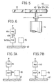
- Fig. 6 there is illustrated a vibration model for the radial direction of the shaft of the platen in the thermal transfer printer of the present invention shown in Fig. 4, in Fig. 7A is illustrated a vibration model for the radial direction of the shaft of the platen for the prior art thermal transfer printer in which no use is made of a buffer, and in Fig.
- FIG. 7B is illustrated a vibration model for the radial direction of the shaft of the platen for the prior art thermal transfer printer in which a buffer is inserted between the bearings and the frame.
- Ma represents the mass of the outer ring 50c of the timing pulley on the platen side
- m is the sum of the masses of the platen 14 and the inner ring 50a of the timing pulley 50
- Mal is the mass of the timing pulley 50
- m al is the mass of the platen 14
- K and Kl represent the spring constant
- F represents the external force that acts on the timing pulley 50 due to the intermittent tension on the timing belt 18.
- the external force F is transmitted to the frame 42 as is beacuse of the rigid joining of the varions elements such as the timing pulley 50 and the shaft 40 of the platen.
- the timing pulley 50 and the platen constitute a system of forced vibration with one degree of freedom. That the transmissibility of the external force F to the frame 42 in this case will be less than unity for the range of frequency which is above the square root of two times the resonance frequency is well known.
- the platen 14 in the vibration model is situated nearer the external force F than the elastic body, the displacement is larger than in the case of rigid joining to the frame as shown in Fig. 7A. Therefore, there is
- Fig. 8 are compared the results of measurement on the acoustic power level for the prior art thermal transfer printer shown in Fig. 7A and for the thermal transfer printer in accordance with the present invention. From the figure, it will be seen that a reduction of 5 dB in the acoustic power level of the noise can be achieved by the use of the device of the present invention.
- FIG. 9 there is illustrated a second embodiment of the thermal transfer printer in accordance with the present invention.
- This embodiment shows an example in which the present invention is applied to the case where a high accuracy in the direction of paper feeding is required for carrying out superposed impressions as for the color printing.
- the buffer cylinder 50b there are created on the buffer cylinder 50b a plurality of equally spaced radial notches 54 that extend from its outer periphery toward the center, and on the inner periphery of the outer ring 50c there are fixed wings 56, consisting of projections that fit the notches 54, that are made of a material, such as metal or plastic, with elastic modulus greater than that for the elastic body constituting the buffer cylinder 50b.
- the torsional spring constant k of a cylindrical anti-vibration rubber piece is given by the following expression.
- G is the shearing modulus
- I is the axial length of the cylinder
- r 1 and r 2 represent the inner and outer radius, respectively.
- Equation (1) may be rewritten as
- the spring constant in the radial direction of the buffer cylinder 50b can be represented as the sum of spring cosntant due to shearing stress and the spring constant due to compression and tension.
- the spring constant due to shearing is small compared with that due to compression and tension so that the spring constant in the radial direction of the cylindrical anti-vibration rubber piece is dominated by the spring constant due to compression and tension. Therefore, even when the torsional spring constant of the buffer cylinder 50b is increased by the wings 56, the increase in the spring constant in the radial direction will not be appreciable. As a result, it becomes possible to suppress the transmissibility vibrations to the platen 14 and the shaft of the platen 40, as well as to secure the accuracy in the direction of paper feeding.
- FIG. 11 there is shown a third embodiment of the thermal transfer printer in accordance with the present invention.
- this embodiment there are provided notches 54a, which are similar to the previous notches 54, on the inner periphery of the buffer cylinder 50b, and on the inner ring 50a of the timing pulley 50 there are provided wings 56a which are similar to the previous wings 56.
- notches 54a which are similar to the previous notches 54
- wings 56a which are similar to the previous wings 56.
- FIG. 12 there is shown a fourth embodiment of the thermal transfer printer in accordance with the present invention.
- wings 56a on the inner ring 50a of the timing pulley and wings 58 on the outer ring 50c of the timing pulley are installed with their respective positions alternating.
- wings 56a on the inner ring 50a of the timing pulley and wings 58 on the outer ring 50c of the timing pulley are installed with their respective positions alternating.
- FIG. 13 there is shown a fifth embodiment of the thermal transfer printer in accordance with the present invention.
- a thermal transfer printer in accordance with the present invention can suppress the generation of the noise created by the intermittent turning of the platen, without reducing the printing accuracy to any degree. Therefore, it can prevent the increase in noise within an office accompanying the spread of office automation.
Landscapes
- Handling Of Sheets (AREA)
Applications Claiming Priority (2)
| Application Number | Priority Date | Filing Date | Title |
|---|---|---|---|
| JP60611/85 | 1985-01-07 | ||
| JP60000611A JPS61160264A (ja) | 1985-01-07 | 1985-01-07 | 熱転写プリンタ |
Publications (2)
| Publication Number | Publication Date |
|---|---|
| EP0187196A1 true EP0187196A1 (fr) | 1986-07-16 |
| EP0187196B1 EP0187196B1 (fr) | 1989-06-14 |
Family
ID=11478522
Family Applications (1)
| Application Number | Title | Priority Date | Filing Date |
|---|---|---|---|
| EP85110877A Expired EP0187196B1 (fr) | 1985-01-07 | 1985-08-29 | Imprimante à transfert thermique |
Country Status (3)
| Country | Link |
|---|---|
| EP (1) | EP0187196B1 (fr) |
| JP (1) | JPS61160264A (fr) |
| DE (1) | DE3571007D1 (fr) |
Cited By (2)
| Publication number | Priority date | Publication date | Assignee | Title |
|---|---|---|---|---|
| US5092690A (en) * | 1989-05-09 | 1992-03-03 | Texas Instruments Incorporated | Portable printer |
| CN111546765A (zh) * | 2020-05-29 | 2020-08-18 | 浙江思迈拓科技有限公司 | 一种笔壳热烫机 |
Citations (4)
| Publication number | Priority date | Publication date | Assignee | Title |
|---|---|---|---|---|
| DE2642380A1 (de) * | 1975-10-03 | 1977-04-07 | Platt Saco Lowell Corp | Leerlauf- bzw. umlenkrolle fuer riementriebe |
| US4366609A (en) * | 1979-09-17 | 1983-01-04 | Dayco Corporation | Composite pulley and method for making |
| EP0098033A2 (fr) * | 1982-06-29 | 1984-01-11 | Kabushiki Kaisha Toshiba | Dispositif d'impression thermique par transfert d'encre |
| US4486183A (en) * | 1980-06-30 | 1984-12-04 | The Gates Rubber Company | Torsionally elastic power transmitting device and drive |
-
1985
- 1985-01-07 JP JP60000611A patent/JPS61160264A/ja active Pending
- 1985-08-29 EP EP85110877A patent/EP0187196B1/fr not_active Expired
- 1985-08-29 DE DE8585110877T patent/DE3571007D1/de not_active Expired
Patent Citations (4)
| Publication number | Priority date | Publication date | Assignee | Title |
|---|---|---|---|---|
| DE2642380A1 (de) * | 1975-10-03 | 1977-04-07 | Platt Saco Lowell Corp | Leerlauf- bzw. umlenkrolle fuer riementriebe |
| US4366609A (en) * | 1979-09-17 | 1983-01-04 | Dayco Corporation | Composite pulley and method for making |
| US4486183A (en) * | 1980-06-30 | 1984-12-04 | The Gates Rubber Company | Torsionally elastic power transmitting device and drive |
| EP0098033A2 (fr) * | 1982-06-29 | 1984-01-11 | Kabushiki Kaisha Toshiba | Dispositif d'impression thermique par transfert d'encre |
Cited By (2)
| Publication number | Priority date | Publication date | Assignee | Title |
|---|---|---|---|---|
| US5092690A (en) * | 1989-05-09 | 1992-03-03 | Texas Instruments Incorporated | Portable printer |
| CN111546765A (zh) * | 2020-05-29 | 2020-08-18 | 浙江思迈拓科技有限公司 | 一种笔壳热烫机 |
Also Published As
| Publication number | Publication date |
|---|---|
| EP0187196B1 (fr) | 1989-06-14 |
| DE3571007D1 (en) | 1989-07-20 |
| JPS61160264A (ja) | 1986-07-19 |
Similar Documents
| Publication | Publication Date | Title |
|---|---|---|
| CA2121958A1 (fr) | Groupe d'engrenages, appareil de formation d'images et methode de montage de groupe d'engrenages | |
| EP0187196A1 (fr) | Imprimante à transfert thermique | |
| KR910016496A (ko) | 전사식 프린터 | |
| US4572681A (en) | Wire dot print head | |
| KR910009065Y1 (ko) | 열전사 프린터 | |
| KR950002361A (ko) | 팩시밀리의 다매급지장치 | |
| JPH0761729B2 (ja) | 印字装置のリボンカセツト | |
| GB2148006A (en) | Vibration preventing device | |
| EP0182006B1 (fr) | Imprimante à transfert thermique | |
| JP4311786B2 (ja) | プリンタ及び被印刷物巻取装置 | |
| JPS61248762A (ja) | プリンタ | |
| JPH02185478A (ja) | プリンタ | |
| JPH045055A (ja) | シリアルプリンタ | |
| JPS60239268A (ja) | 印字装置 | |
| JPS6189064A (ja) | プリンタのプラテン駆動装置 | |
| JPH0478536B2 (fr) | ||
| JP2004264688A (ja) | 像担持体駆動機構 | |
| JP2508477Y2 (ja) | ト―ショナルダンパ | |
| JPS61137765A (ja) | 熱転写プリンタ | |
| JPH0732070Y2 (ja) | プリンタ | |
| JPS6280068A (ja) | インパクト式プリンタ | |
| EP0523869A2 (fr) | Dispositif de contrôle du bruit et des vibrations d'une courroie | |
| JP2585709Y2 (ja) | プリンタの排紙機構 | |
| JPS5842121Y2 (ja) | スポ−ク形プリントホイ−ル | |
| JPH09277627A (ja) | 紙送りトラクタ |
Legal Events
| Date | Code | Title | Description |
|---|---|---|---|
| PUAI | Public reference made under article 153(3) epc to a published international application that has entered the european phase |
Free format text: ORIGINAL CODE: 0009012 |
|
| 17P | Request for examination filed |
Effective date: 19850829 |
|
| AK | Designated contracting states |
Kind code of ref document: A1 Designated state(s): DE FR GB NL |
|
| 17Q | First examination report despatched |
Effective date: 19880108 |
|
| GRAA | (expected) grant |
Free format text: ORIGINAL CODE: 0009210 |
|
| AK | Designated contracting states |
Kind code of ref document: B1 Designated state(s): DE FR GB NL |
|
| REF | Corresponds to: |
Ref document number: 3571007 Country of ref document: DE Date of ref document: 19890720 |
|
| ET | Fr: translation filed | ||
| PLBE | No opposition filed within time limit |
Free format text: ORIGINAL CODE: 0009261 |
|
| STAA | Information on the status of an ep patent application or granted ep patent |
Free format text: STATUS: NO OPPOSITION FILED WITHIN TIME LIMIT |
|
| 26N | No opposition filed | ||
| REG | Reference to a national code |
Ref country code: GB Ref legal event code: 746 Effective date: 19981026 |
|
| REG | Reference to a national code |
Ref country code: FR Ref legal event code: D6 |
|
| PGFP | Annual fee paid to national office [announced via postgrant information from national office to epo] |
Ref country code: FR Payment date: 19990810 Year of fee payment: 15 |
|
| PGFP | Annual fee paid to national office [announced via postgrant information from national office to epo] |
Ref country code: GB Payment date: 19990825 Year of fee payment: 15 |
|
| PGFP | Annual fee paid to national office [announced via postgrant information from national office to epo] |
Ref country code: DE Payment date: 19990827 Year of fee payment: 15 |
|
| PGFP | Annual fee paid to national office [announced via postgrant information from national office to epo] |
Ref country code: NL Payment date: 19990830 Year of fee payment: 15 |
|
| PG25 | Lapsed in a contracting state [announced via postgrant information from national office to epo] |
Ref country code: GB Free format text: LAPSE BECAUSE OF NON-PAYMENT OF DUE FEES Effective date: 20000829 |
|
| PG25 | Lapsed in a contracting state [announced via postgrant information from national office to epo] |
Ref country code: NL Free format text: LAPSE BECAUSE OF NON-PAYMENT OF DUE FEES Effective date: 20010301 |
|
| GBPC | Gb: european patent ceased through non-payment of renewal fee |
Effective date: 20000829 |
|
| PG25 | Lapsed in a contracting state [announced via postgrant information from national office to epo] |
Ref country code: FR Free format text: LAPSE BECAUSE OF NON-PAYMENT OF DUE FEES Effective date: 20010430 |
|
| NLV4 | Nl: lapsed or anulled due to non-payment of the annual fee |
Effective date: 20010301 |
|
| PG25 | Lapsed in a contracting state [announced via postgrant information from national office to epo] |
Ref country code: DE Free format text: LAPSE BECAUSE OF NON-PAYMENT OF DUE FEES Effective date: 20010501 |
|
| REG | Reference to a national code |
Ref country code: FR Ref legal event code: ST |