EP0187409A1 - Unité d'alésage avec suspension du cardan pour l'alignement suivant la normale et avec moyens de pressage - Google Patents
Unité d'alésage avec suspension du cardan pour l'alignement suivant la normale et avec moyens de pressage Download PDFInfo
- Publication number
- EP0187409A1 EP0187409A1 EP85201977A EP85201977A EP0187409A1 EP 0187409 A1 EP0187409 A1 EP 0187409A1 EP 85201977 A EP85201977 A EP 85201977A EP 85201977 A EP85201977 A EP 85201977A EP 0187409 A1 EP0187409 A1 EP 0187409A1
- Authority
- EP
- European Patent Office
- Prior art keywords
- drilling
- workpiece
- clamp
- outer housing
- bore
- Prior art date
- Legal status (The legal status is an assumption and is not a legal conclusion. Google has not performed a legal analysis and makes no representation as to the accuracy of the status listed.)
- Granted
Links
Images



Classifications
-
- B—PERFORMING OPERATIONS; TRANSPORTING
- B23—MACHINE TOOLS; METAL-WORKING NOT OTHERWISE PROVIDED FOR
- B23Q—DETAILS, COMPONENTS, OR ACCESSORIES FOR MACHINE TOOLS, e.g. ARRANGEMENTS FOR COPYING OR CONTROLLING; MACHINE TOOLS IN GENERAL CHARACTERISED BY THE CONSTRUCTION OF PARTICULAR DETAILS OR COMPONENTS; COMBINATIONS OR ASSOCIATIONS OF METAL-WORKING MACHINES, NOT DIRECTED TO A PARTICULAR RESULT
- B23Q9/00—Arrangements for supporting or guiding portable metal-working machines or apparatus
- B23Q9/0014—Portable machines provided with or cooperating with guide means supported directly by the workpiece during action
-
- B—PERFORMING OPERATIONS; TRANSPORTING
- B23—MACHINE TOOLS; METAL-WORKING NOT OTHERWISE PROVIDED FOR
- B23Q—DETAILS, COMPONENTS, OR ACCESSORIES FOR MACHINE TOOLS, e.g. ARRANGEMENTS FOR COPYING OR CONTROLLING; MACHINE TOOLS IN GENERAL CHARACTERISED BY THE CONSTRUCTION OF PARTICULAR DETAILS OR COMPONENTS; COMBINATIONS OR ASSOCIATIONS OF METAL-WORKING MACHINES, NOT DIRECTED TO A PARTICULAR RESULT
- B23Q3/00—Devices holding, supporting, or positioning work or tools, of a kind normally removable from the machine
- B23Q3/002—Means to press a workpiece against a guide
-
- Y—GENERAL TAGGING OF NEW TECHNOLOGICAL DEVELOPMENTS; GENERAL TAGGING OF CROSS-SECTIONAL TECHNOLOGIES SPANNING OVER SEVERAL SECTIONS OF THE IPC; TECHNICAL SUBJECTS COVERED BY FORMER USPC CROSS-REFERENCE ART COLLECTIONS [XRACs] AND DIGESTS
- Y10—TECHNICAL SUBJECTS COVERED BY FORMER USPC
- Y10T—TECHNICAL SUBJECTS COVERED BY FORMER US CLASSIFICATION
- Y10T408/00—Cutting by use of rotating axially moving tool
- Y10T408/55—Cutting by use of rotating axially moving tool with work-engaging structure other than Tool or tool-support
- Y10T408/561—Having tool-opposing, work-engaging surface
- Y10T408/5612—Tool having shiftable tool-axis
-
- Y—GENERAL TAGGING OF NEW TECHNOLOGICAL DEVELOPMENTS; GENERAL TAGGING OF CROSS-SECTIONAL TECHNOLOGIES SPANNING OVER SEVERAL SECTIONS OF THE IPC; TECHNICAL SUBJECTS COVERED BY FORMER USPC CROSS-REFERENCE ART COLLECTIONS [XRACs] AND DIGESTS
- Y10—TECHNICAL SUBJECTS COVERED BY FORMER USPC
- Y10T—TECHNICAL SUBJECTS COVERED BY FORMER US CLASSIFICATION
- Y10T408/00—Cutting by use of rotating axially moving tool
- Y10T408/55—Cutting by use of rotating axially moving tool with work-engaging structure other than Tool or tool-support
- Y10T408/564—Movable relative to Tool along tool-axis
- Y10T408/5647—Movable relative to Tool along tool-axis including means to move Tool
-
- Y—GENERAL TAGGING OF NEW TECHNOLOGICAL DEVELOPMENTS; GENERAL TAGGING OF CROSS-SECTIONAL TECHNOLOGIES SPANNING OVER SEVERAL SECTIONS OF THE IPC; TECHNICAL SUBJECTS COVERED BY FORMER USPC CROSS-REFERENCE ART COLLECTIONS [XRACs] AND DIGESTS
- Y10—TECHNICAL SUBJECTS COVERED BY FORMER USPC
- Y10T—TECHNICAL SUBJECTS COVERED BY FORMER US CLASSIFICATION
- Y10T408/00—Cutting by use of rotating axially moving tool
- Y10T408/65—Means to drive tool
- Y10T408/675—Means to drive tool including means to move Tool along tool-axis
- Y10T408/6793—Screw coaxial with Tool
-
- Y—GENERAL TAGGING OF NEW TECHNOLOGICAL DEVELOPMENTS; GENERAL TAGGING OF CROSS-SECTIONAL TECHNOLOGIES SPANNING OVER SEVERAL SECTIONS OF THE IPC; TECHNICAL SUBJECTS COVERED BY FORMER USPC CROSS-REFERENCE ART COLLECTIONS [XRACs] AND DIGESTS
- Y10—TECHNICAL SUBJECTS COVERED BY FORMER USPC
- Y10T—TECHNICAL SUBJECTS COVERED BY FORMER US CLASSIFICATION
- Y10T408/00—Cutting by use of rotating axially moving tool
- Y10T408/91—Machine frame
- Y10T408/93—Machine frame including pivotally mounted tool-carrier
-
- Y—GENERAL TAGGING OF NEW TECHNOLOGICAL DEVELOPMENTS; GENERAL TAGGING OF CROSS-SECTIONAL TECHNOLOGIES SPANNING OVER SEVERAL SECTIONS OF THE IPC; TECHNICAL SUBJECTS COVERED BY FORMER USPC CROSS-REFERENCE ART COLLECTIONS [XRACs] AND DIGESTS
- Y10—TECHNICAL SUBJECTS COVERED BY FORMER USPC
- Y10T—TECHNICAL SUBJECTS COVERED BY FORMER US CLASSIFICATION
- Y10T409/00—Gear cutting, milling, or planing
- Y10T409/30—Milling
- Y10T409/30784—Milling including means to adustably position cutter
- Y10T409/307952—Linear adjustment
- Y10T409/308232—Linear adjustment and angular adjustment
-
- Y—GENERAL TAGGING OF NEW TECHNOLOGICAL DEVELOPMENTS; GENERAL TAGGING OF CROSS-SECTIONAL TECHNOLOGIES SPANNING OVER SEVERAL SECTIONS OF THE IPC; TECHNICAL SUBJECTS COVERED BY FORMER USPC CROSS-REFERENCE ART COLLECTIONS [XRACs] AND DIGESTS
- Y10—TECHNICAL SUBJECTS COVERED BY FORMER USPC
- Y10T—TECHNICAL SUBJECTS COVERED BY FORMER US CLASSIFICATION
- Y10T409/00—Gear cutting, milling, or planing
- Y10T409/30—Milling
- Y10T409/30784—Milling including means to adustably position cutter
- Y10T409/308512—Compound angular adjustment
Definitions
- This invention relates to drills and the like. More particularly, it relates to normalizing a drill bit relative to the surface of a workpiece in which a bore is to be drilled.
- This invention relates to problems associated with drilling a bore normal to the surface of a workpiece.
- common drill presses have a fixed spindle axis that is perpendicular or normal to a horizontal drill table.
- a workpiece may be secured to the drill table by either a vise or similar fixture which makes up a portion of the table.
- the workpiece or other part to be drilled may or may not be positioned at a right angle to the drill spindle axis. In such a case, the workpiece must be positioned in the vise so that the workpiece surface is perpendicular to the spindle axis. This practice is, of course, time consuming and expensive.
- a problem especially pertinent to drilling bores in curved surfaces is that often times the drill bit may tend to skid across the surface as it begins to drill a particular bore.
- drill point skidding has sometimes been prevented by providing a drill bushing that is connected to the vise or similar fixture.
- the present invention provides a drilling apparatus for drilling a bore in a workpiece, wherein the bore is drilled substantially normal to the surface of the workpiece.
- the apparatus comprises a drilling member or bit that is rotatable about an axis for drilling the bore.
- a drive means is included for rotating the bit and for advancing it toward and against the workpiece surface to drill the bore.
- a gimbal means connected to the drive means, normalizes the bit as the bore is drilled.
- the gimbal means guides the bit toward a drilling point on the surface of the workpiece, wherein the drilling point is positioned substantially tangent to the surface of the workpiece.
- the bit is guided so that the bit's drilling axis remains substantially normal to the drilling point while the bore is drilled.
- the drilling apparatus includes an inner housing that receives the drive means and which supports the drilling bit.
- An outer housing surrounds the inner housing.
- a gimbal member connects the inner housing to the outer housing so that the inner housing may pivot relative to the outer housing, which in turn causes the drilling axis to pivot relative to the outer housing.
- the gimbal member is fixedly connected to the inner housing and has a plurality of pressure feet which abut against the surface of the workpiece.
- the pressure feet are arranged so that they are equidistant from each other with the drilling axis being positioned centrally with respect to them.
- the pressure feet and the surface of the workpiece define a drill datum plane that intersects each location on the surface of the workpiece where a pressure foot contacts the surface.
- the drilling point is located on the datum plane at the point where the drilling axis intersects the plane.
- the gimbal member includes a surface that has a spherical portion which is defined by a radius that originates at the drilling point.
- the outer housing includes a bearing surface that is shaped to slide adjacent the spherical surface portion of the gimbal member. This provides a means for pivoting the inner housing, and the drill axis, relative to the outer housing when the pressure feet are placed against the workpiece surface.
- a positioning means in the form of an automatic traversing drilling unit, a robot arm, a drill press, or the like is connected to the outer housing of the drilling apparatus.
- the positioning means moves the apparatus to various positions on a particular workpiece or workpieces for drilling holes therein.
- the pressure feet When the apparatus is positioned adjacent the workpiece the pressure feet first contact the workpiece surface which pivots the drilling axis and normalizes the drilling bit.
- a clamp-up means then thrusts the pressure feet against the surface of the workpiece with a certain preselected clamp-up pressure.
- the clamp-up means may comprise first and second portions of the outer housing which are movable relative to each other.
- the first portion of the outer housing is connected to the positioning means.
- the second portion of the outer housing is connected to the bearing surface of the outer housing.
- An actuator means is provided for moving the second portion relative to the first, to in this manner cause the bearing surface to thrust against the spherical surface portion of the gimbal member. This thrust is transmitted through the gimbal member to the pressure feet which causes the pressure feet to abut against the workpiece surface with a certain clamp-up pressure or force.
- the actuator means may be in the form of an electric feed motor, a hydraulic actuator, or a pneumatic actuator.
- a thrust sensor may be mounted to the outer housing in operative position between the positioning means and the bearing surface of the outer housing so as to monitor the thrust provided by the clamp-up means.
- the thrust sensor could, for example, be in the form of a strain gauge mounted to the first portion of the outer housing.
- the thrust sensor would provide a means for adjusting the clamp-up pressure which the pressure feet apply to the workpiece surface.
- the drive means which rotates and advances the drill bit, includes a spindle shaft that is received within the inner housing.
- the spindle shaft includes a rotating portion, connected to the bit, and a nonrotating portion.
- the rotating portion is connected to- spindle motor which drives the bit in rotation.
- the nonrotating portion is connected to a feed motor which advances the shaft towards the workpiece.
- the rotating and nonrotating portions are connected together by a rotary thrust coupling member.
- An important advantage to the present invention is that it provides a quick and easy means for drilling a bore normal to the surface of a workpiece.
- Another advantage of the present invention is that it provides a means for clamping the drilling apparatus to a workpiece with sufficient force so that the apparatus will not translate relative to the workpiece surface as the bore is drilled.
- This has a number of effects. First, it eliminates drill skid. Second, it ensures that the bore will be drilled normal to the surface of the workpiece for its entire length. Third, when a countersink is provided in the bore, a sufficient clamp-up force will ensure that the countersink remains in concentric relationship relative to the drilling axis. Further, clamp-up pressure ensures that no gaps occur between multi strata in the workpiece which thereby eliminates burrs and chips between the layers. The amount of pressure applied also takes into account the structural stability of the workpiece itself.
- Still another advantage to the present invention is that it provides a datum plane that may be used as a depth register for determining the depth of the bore as it is being drilled. This is important when drilling bores that, for example, have a countersink portion for receiving the head of a rivet or the like. It is critical to know the point at which to stop drilling the bore so that the rivet can fit into the bore with the rivet head being substantially flush with the surface of the workpiece.
- Still another advantage to the present invention is that it is well suited for adaptation to computerized control.
- the rotation and advancement of the drilling bit for bore depth may be controlled by a computer.
- control of clamp-up pressure may also be computer controlled.
- the apparatus 10 is positioned adjacent a workpiece 12 for drilling a bore therein.
- the apparatus 10 includes an inner housing 14 that is connected to an outer housing 16 by a gimbal member 18.
- the inner housing 14 supports a drill bit 20 which is driven by a spindle shaft 22.
- the spindle shaft 22 is received within the inner housing and extends downwardly through an opening 23 in the gimbal member 18.
- the spindle shaft has a rotating portion 24 and a nonrotating portion 26 which are connected together by a rotary thrust coupling 28.
- the upper portion of the inner housing 14 has a feed motor 30 connected to threads 31 on the nonrotating portion 26 of the spindle shaft 22.
- the feed motor 30 moves the spindle shaft 20 axially toward and away from the workpiece 12. In this manner, the drill bit 20 may be advanced toward and against the surface 32 of the workpiece 12 with a desired feed rate.
- the lower portion of the inner housing 14 includes a spindle motor 34 that is connected to a splined rotating portion 24 of the spindle shaft 22. Rotation of the rotating portion 24 causes the drill bit to rotate for the purpose of drilling a bore.
- the gimbal member 18 is fixedly connected to the inner housing 14 by means of an annular, outwardly radiating flange portion 36, which is bolted to the casing of the spindle motor 34.
- the gimbal member 18 includes a portion 38 having a spherical surface.
- the outer housing 16 includes an annular bearing surface 40 shaped to slide adjacent the spherical surface portion 38 of the gimbal member 18. The sliding movement of the bearing surface 40 relative to the spherical surface 38 permits the inner housing 14 to pivot relative to the outer housing 16. This, of course, also permits the spindle shaft 22 and drill bit 20 to pivot.
- the gimbal member 18 includes three pressure feet 42 which extend downwardly from the gimbal member.
- the pressure feet 42 are spaced equidistant from each other and abut against the surface 32 of the workpiece 12.
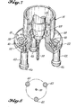
- the longitudinal axis of the drill bit 20 (and the spindle shaft 22) is positioned centrally between the pressure feet 42. This is best shown in Figs. 7 and 8, which illustrate a second embodiment of the invention that is to be described later.
- a datum plane 44 is defined by the locations 46 where the pressure feet 42 contact the workpiece surface 32.
- the datum plane 44 intersects each location 46 where a pressure foot contacts the workpiece surface 32.
- the spherical surface portion 38 of the gimbal member-18 is defined by a radius 50 which originates at the point where the axis 45 of the bit 20 intersects the datum plane 44. This point of intersection defines a drilling point 48 for drilling a bore in the workpiece 12. Therefore, as can be seen from the drawings, the pressure feet 42 define a datum plane 44 which is substantially tangent to the surface 32 of the workpiece 12.
- the drilling point 48 for the bore is positioned on the datum plane 44 and therefore will also be substantially tangent to the surface 32.
- the apparatus 10 shown and described herein is to be used in conjunction with some sort of means for positioning the apparatus adjacent a workpiece.
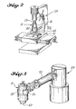
- the apparatus 10 is well suited for adaptation to a standard drill press 52.
- the apparatus 10 is shown in this Fig. mounted to a spindle arm 53 which is vertically movable.
- the apparatus 10 could be used in conjunction with an automatically controlled robot 54.
- the robot 54 would have an arm portion 55 that grasps the apparatus 10 by means of gripping members 56, 58 for positioning the apparatus adjacent a workpiece.
- the apparatus 10 is shown wherein the outer housing 16 is held by the gripping members 56, 58 of the robot 54.
- a pneumatic actuator indicated generally by arrow 60, and constructed as a portion of the outer housing 16, may provide a clamp-up force for clamping the pressure feet 42 against the workpiece surface 32.
- a first portion 62 of the outer housing is connected to the gripping members 56, 58 of the positioning means.
- a second portion 64 of the outer housing is directly connected to the annular bearing surface 40, which slides adjacent the spherical surface portion 38 of the gimbal member 18.
- both the first and second portions are cylindrical members, wherein the outer sidewall 66 of the second portion is in sliding contact with the inner sidewall 68 of the first portion 62.
- the lower part of the first portion 62 projects radially outwardly so as to provide an annular chamber 72 between the outer sidewall 66 of the second portion 64, and the inner sidewall 68 of the first portion.
- the annular chamber 72 is divided by an outwardly projecting flange 78 that is connected to the outer sidewall 66 of the second portion 64 of the outer housing 16. This flange 78 separates the chamber 72 into upper and lower chambers 74, 76.
- Air inlet/outlet ports 80, 82 may be connected to each of the chambers 74, 76.
- the second portion 64 of the outer housing is thrust downwardly with respect to the first portion 62.
- This thrust is transferred by the bearing surface 40 onto the spherical surface portion 38 of the gimbal member, and is further transmitted to the pressure feet.
- the thrust provided by the actuator 60 therefore provides a clamp-up force that ensures that the apparatus 10 will remain in a stationary position relative to the workpiece surface 32 as the bore is drilled. For example, by having a sufficient clamp-up force, there will be little or no sideways translation of the drill bit 20 as the bore is drilled.
- the clamp-up force m.xy be used to hold the several layers together as the bore is drilled.
- a seal 70 may be provided between the outer sidewall 66 of the second portion 64 and the inner sidewall 68 of the first portion 62 for preventing air leakage from the upper and lower chambers 74, 76.
- the spherical surface portion 38 of the gimbal member 18 is held adjacent the bearing surface 40 of the outer housing 16 by means of a diaphragm spring 84.
- the top portion 90 of the outer housing 16 may be provided with an opening 92 through which the nonrotating portion 26 of the spindle shaft 22 extends.
- the opening 92 would provide a structural constraint limiting the amount of back and forth movement of the spindle shaft 22.
- the opening 92 may be covered with a rubber material 94 to prevent the spindle shaft 22 and/or the outer housing 16 from being damaged when the apparatus 10 is moved from position to position adjacent a workpiece, or when the apparatus is moved between different workpieces.
- FIG. 4-8 Another embodiment of the invention is shown in Figs. 4-8.
- the apparatus 10 is shown mounted to an automatic traversing drilling unit, indicated generally by 96, wherein the apparatus 10 may be used to drill a series of holes in a body panel or the like.
- Such a traversing drilling unit was disclosed (Boeing Co. invention disclosure No. 81-0263) in a patent application filed on under U.S. Serial No. .
- the apparatus 10 is shown connected to a pair of carriages 98, 100 of the unit 96, wherein one carriage is positioned on each side of the apparatus.
- the apparatus 10 is attached to the carriages 98, 100 by means of outwardly extending linkage members or rods 102, 104.
- the apparatus 10 shown in Figs. 4-8 is the same as the apparatus shown in Fig. 1, with a few alterations.
- the apparatus 10 shown therein has the same gimbal member 18, with the gimbal member having a spherically shaped surface portion 38.
- the outer housing 16 is fixedly connected to the linkage rods 104 and 102 and therefore cannot move relative to the carriages 98, 100 of the traversing drilling unit 96.
- a clamp-up motor 112 which in this case may be in the form of a hollow nut electric motor, is connected to the first and second portions 110, 108 of the outer housing 16 in such a manner so that the clamp-up motor may be operated to slide the second portion 108 relative to the first 110.
- FIGs. 4-7 includes an annular support shoulder 112 which prevents the inner housing 14 from falling free of the outer housing 16 when the apparatus 10 is lifted away from the workpiece surface 32.
- the drill bit 20 is driven in much the same manner as the embodiment shown in Fig. 1. In the later embodiment, however, the rotating portion of the spindle 22 is driven by an air driven motor 106.
- the spindle 22 is hollow for providing an air passageway 114 to supply air to the motor 106. Air for driving the motor 106 may be input through an end of the spindle shaft 22, which is indicated generally by arrow l16.
- the spindle shaft 22 is advanced toward the workpiece by an electric feed motor 118 mounted to the top portion of the apparatus 10.
- a linkage arm 120 connected to both the feed motor 118 and the clamp-up motor 112, prevents rotation of the feed motor l18 relative to the outer housing 16.
Landscapes
- Engineering & Computer Science (AREA)
- Mechanical Engineering (AREA)
- Drilling And Boring (AREA)
Applications Claiming Priority (2)
| Application Number | Priority Date | Filing Date | Title |
|---|---|---|---|
| US687520 | 1984-12-28 | ||
| US06/687,520 US4613262A (en) | 1984-12-28 | 1984-12-28 | Drill motor assembly with gimbal normality and clamp-up capability |
Publications (2)
| Publication Number | Publication Date |
|---|---|
| EP0187409A1 true EP0187409A1 (fr) | 1986-07-16 |
| EP0187409B1 EP0187409B1 (fr) | 1989-03-22 |
Family
ID=24760742
Family Applications (1)
| Application Number | Title | Priority Date | Filing Date |
|---|---|---|---|
| EP85201977A Expired EP0187409B1 (fr) | 1984-12-28 | 1985-11-26 | Unité d'alésage avec suspension du cardan pour l'alignement suivant la normale et avec moyens de pressage |
Country Status (3)
| Country | Link |
|---|---|
| US (1) | US4613262A (fr) |
| EP (1) | EP0187409B1 (fr) |
| DE (1) | DE3568953D1 (fr) |
Cited By (6)
| Publication number | Priority date | Publication date | Assignee | Title |
|---|---|---|---|---|
| EP2808110A1 (fr) * | 2013-05-27 | 2014-12-03 | Fuji Jukogyo Kabushiki Kaisha | Procédé de forage et appareil de forage |
| FR3030325A1 (fr) * | 2014-12-23 | 2016-06-24 | Airbus Group Sas | Procede de percage et machine pour la mise en oeuvre de ce procede |
| EP3275579A1 (fr) * | 2016-07-29 | 2018-01-31 | Seti-Tec | Dispositif de perçage à vitesse d'avance automatique ou contrôlée à broche auto alignante |
| CN108067655A (zh) * | 2017-12-13 | 2018-05-25 | 芜湖市皖南造船有限公司 | 一种简易钻孔机 |
| EP3778134A1 (fr) * | 2019-08-14 | 2021-02-17 | The Boeing Company | Dispositif de positionnement pour un appareil de forage |
| CN113710417A (zh) * | 2019-04-17 | 2021-11-26 | 罗信2002有限公司 | 具有主动校正的加工头、用于操作加工头的方法及其用途 |
Families Citing this family (24)
| Publication number | Priority date | Publication date | Assignee | Title |
|---|---|---|---|---|
| US4778317A (en) * | 1986-01-13 | 1988-10-18 | Ltv Aerospace & Defense Company | Tactile sensing tool positioning system |
| US4999896A (en) * | 1989-10-25 | 1991-03-19 | Gemcor Engineering Corporation | Automatic double-flush riveting |
| US5299894A (en) * | 1992-12-23 | 1994-04-05 | The Boeing Company | Workpiece positioning and drilling end effector |
| US5482409A (en) * | 1993-01-06 | 1996-01-09 | The Boeing Company | Part positioning and drilling end effector |
| US5860900A (en) * | 1993-01-06 | 1999-01-19 | The Boeing Company | End effector storage station |
| US5383751A (en) * | 1993-08-05 | 1995-01-24 | Vought Aircraft Company | Manually positioned computer controlled drilling machine |
| US5468099A (en) * | 1993-08-11 | 1995-11-21 | Vought Aircraft Company | Seam tracking drilling machine |
| US5404641A (en) * | 1993-08-16 | 1995-04-11 | Avco Corporation | Method of drilling through contiguous plate members using a robotic drill clamp |
| DE19514379A1 (de) * | 1995-04-19 | 1996-10-24 | Fischer Artur Werke Gmbh | Bohrvorrichtung zur Herstellung von Bohrlöchern mit Hinterschneidung |
| US5769576A (en) * | 1995-06-13 | 1998-06-23 | Machines Serdi | Device for positioning a machining spindle using its pilot rod |
| US5848859A (en) * | 1997-01-08 | 1998-12-15 | The Boeing Company | Self normalizing drill head |
| US6382889B1 (en) * | 2001-02-12 | 2002-05-07 | The Boeing Company | Portable multi-axis machine |
| DE102004051915B4 (de) * | 2004-10-26 | 2012-11-22 | Airbus Operations Gmbh | Vorrichtung zur Bearbeitung von Bauteilen für Verkehrsmittel |
| US20060269369A1 (en) * | 2005-05-24 | 2006-11-30 | The Boeing Company | Portable electro-pneumatic drill apparatus |
| ES2319028B1 (es) * | 2007-02-26 | 2010-02-10 | Airbus España, S.L. | Boquilla porta-avellanador. |
| US8511945B2 (en) * | 2008-03-28 | 2013-08-20 | Quanser Consulting Inc. | Drill assembly and method to reduce drill bit plunge |
| DE102009012155A1 (de) * | 2009-03-06 | 2010-09-09 | Thyssenkrupp Drauz Nothelfer Gmbh | Bearbeitungseinrichtung zur Bearbeitung eines Werkstücks |
| US20130259589A1 (en) * | 2012-03-29 | 2013-10-03 | Honda Motor Co., Ltd. | Tapping apparatus, accessory, and use thereof |
| JP2014073571A (ja) * | 2012-10-05 | 2014-04-24 | Mitsubishi Heavy Ind Ltd | 面直倣い機構、これを備えた加工装置および加工方法 |
| US9259792B2 (en) * | 2013-08-26 | 2016-02-16 | The Boeing Company | 5-axis hole transfer system and method |
| FR3015330B1 (fr) * | 2013-12-24 | 2016-02-05 | Plastic Omnium Cie | Outil rotatif d'enlevement de matiere d'une piece en matiere plastique |
| JP6542081B2 (ja) * | 2015-09-14 | 2019-07-10 | 三菱重工業株式会社 | ガイド装置およびスカーフ加工面形成方法 |
| EP3369525A1 (fr) * | 2017-03-01 | 2018-09-05 | Airbus SAS | Système de fixation d'un outil robotique sur une pièce |
| CN116967503B (zh) * | 2023-08-10 | 2025-09-09 | 中航成飞民用飞机有限责任公司 | 飞机曲面叠层结构的制孔辅助装置及制孔方法 |
Citations (5)
| Publication number | Priority date | Publication date | Assignee | Title |
|---|---|---|---|---|
| US2963927A (en) * | 1959-10-26 | 1960-12-13 | Boeing Co | Self aligning drill motor clamp |
| US3973859A (en) * | 1975-02-24 | 1976-08-10 | Grumman Aerospace Corporation | Automated drilling system |
| US4332066A (en) * | 1980-01-07 | 1982-06-01 | General Dynamics Corporation | Compliance mechanism |
| GB2103127A (en) * | 1981-08-05 | 1983-02-16 | British Aerospace | Machining tool, e.g, drill, positioning devices |
| GB2103126A (en) * | 1981-08-05 | 1983-02-16 | British Aerospace | Machining tool, e.g. drill, positioning devices |
Family Cites Families (15)
| Publication number | Priority date | Publication date | Assignee | Title |
|---|---|---|---|---|
| US1881185A (en) * | 1929-11-23 | 1932-10-04 | Cincinnati Shaper Co | Hydraulic hold-down |
| US2357579A (en) * | 1942-04-18 | 1944-09-05 | Frank A Conway | Drill fixture |
| US2640515A (en) * | 1948-04-14 | 1953-06-02 | Reiss Mfg Corp | Boring or drilling machine and work holding clamp |
| US2891427A (en) * | 1955-01-17 | 1959-06-23 | Northrop Corp | Machine for drilling and precision countersinking |
| US3259023A (en) * | 1965-01-08 | 1966-07-05 | Applied Machine Res Inc | Metal working machine and machining process |
| US3469475A (en) * | 1967-02-27 | 1969-09-30 | Sperry Canada Ltd | Apparatus for maintaining positional stability between a tool member and a workpiece |
| US3552069A (en) * | 1967-08-04 | 1971-01-05 | Nat Automatic Tool Co | Floating seat structure for honing machines and the like |
| US3565142A (en) * | 1969-04-29 | 1971-02-23 | Goodspeed Machine Co | Automatic drilling machine |
| AT325377B (de) * | 1972-10-18 | 1975-10-27 | V Pt I Energet Mash | Drehbarer arbeitstisch für werkzeugmaschinen |
| US4254676A (en) * | 1977-10-29 | 1981-03-10 | Pratt Burnerd International Limited | Workholding |
| DE2817218A1 (de) * | 1978-04-20 | 1979-10-31 | Trumpf Maschinen Ag | Werkzeugmaschine |
| US4198180A (en) * | 1978-05-11 | 1980-04-15 | Mcdonnell Douglas Corporation | Thrust controlled drilling apparatus |
| FR2437909A1 (fr) * | 1978-10-06 | 1980-04-30 | Vierstraete Jean | Dispositif tournant de compression de pieces plates fixe sur un des elements d'usinage d'une machine-outil |
| US4251174A (en) * | 1979-02-28 | 1981-02-17 | Mcdonnell Douglas Corporation | Roller hold down |
| US4310269A (en) * | 1980-02-19 | 1982-01-12 | Northrop Corporation | Drill break-through sensor |
-
1984
- 1984-12-28 US US06/687,520 patent/US4613262A/en not_active Expired - Fee Related
-
1985
- 1985-11-26 DE DE8585201977T patent/DE3568953D1/de not_active Expired
- 1985-11-26 EP EP85201977A patent/EP0187409B1/fr not_active Expired
Patent Citations (5)
| Publication number | Priority date | Publication date | Assignee | Title |
|---|---|---|---|---|
| US2963927A (en) * | 1959-10-26 | 1960-12-13 | Boeing Co | Self aligning drill motor clamp |
| US3973859A (en) * | 1975-02-24 | 1976-08-10 | Grumman Aerospace Corporation | Automated drilling system |
| US4332066A (en) * | 1980-01-07 | 1982-06-01 | General Dynamics Corporation | Compliance mechanism |
| GB2103127A (en) * | 1981-08-05 | 1983-02-16 | British Aerospace | Machining tool, e.g, drill, positioning devices |
| GB2103126A (en) * | 1981-08-05 | 1983-02-16 | British Aerospace | Machining tool, e.g. drill, positioning devices |
Non-Patent Citations (1)
| Title |
|---|
| IBM TECHNICAL DISCLOSURE BULLETIN, vol. 25, no. 6, November 1982, pages 3062, 3063; P.W. JUHL et al.: "Rotary tool-end effector for a robot" * |
Cited By (10)
| Publication number | Priority date | Publication date | Assignee | Title |
|---|---|---|---|---|
| EP2808110A1 (fr) * | 2013-05-27 | 2014-12-03 | Fuji Jukogyo Kabushiki Kaisha | Procédé de forage et appareil de forage |
| FR3030325A1 (fr) * | 2014-12-23 | 2016-06-24 | Airbus Group Sas | Procede de percage et machine pour la mise en oeuvre de ce procede |
| WO2016102392A1 (fr) * | 2014-12-23 | 2016-06-30 | Airbus Group Sas | Procédé de perçage et machine pour la mise en oeuvre de ce procédé |
| EP3275579A1 (fr) * | 2016-07-29 | 2018-01-31 | Seti-Tec | Dispositif de perçage à vitesse d'avance automatique ou contrôlée à broche auto alignante |
| FR3054463A1 (fr) * | 2016-07-29 | 2018-02-02 | Seti-Tec | Dispositif de percage a vitesse d'avance automatique ou controlee a broche auto alignante |
| US10279446B2 (en) | 2016-07-29 | 2019-05-07 | Seti-Tec | Drilling device with automatic or controlled feed speed with self-aligning spindle |
| CN108067655A (zh) * | 2017-12-13 | 2018-05-25 | 芜湖市皖南造船有限公司 | 一种简易钻孔机 |
| CN113710417A (zh) * | 2019-04-17 | 2021-11-26 | 罗信2002有限公司 | 具有主动校正的加工头、用于操作加工头的方法及其用途 |
| EP3778134A1 (fr) * | 2019-08-14 | 2021-02-17 | The Boeing Company | Dispositif de positionnement pour un appareil de forage |
| US11123835B2 (en) | 2019-08-14 | 2021-09-21 | The Boeing Company | Positioning device for a drilling apparatus |
Also Published As
| Publication number | Publication date |
|---|---|
| US4613262A (en) | 1986-09-23 |
| DE3568953D1 (en) | 1989-04-27 |
| EP0187409B1 (fr) | 1989-03-22 |
Similar Documents
| Publication | Publication Date | Title |
|---|---|---|
| US4613262A (en) | Drill motor assembly with gimbal normality and clamp-up capability | |
| KR950001774B1 (ko) | 캘리퍼 가공 장치 및 방법과 캘리퍼 가공용 지그 | |
| US4907337A (en) | Apparatus for machining a workpiece of wood, in particular wood beams | |
| DE602005005889T2 (de) | Werkzeugspindelkopf mit einer Messvorrichtung zur Tiefenkontrolle | |
| US5161921A (en) | Method and equipment designed to drill countersunk holes on surfaces in any position | |
| US4622871A (en) | Cutting tool compensator for stationary machine tool | |
| JP3998728B2 (ja) | 基体を有する工具、及びこのような工具を用いてワークピースに孔を穿孔する方法 | |
| US4813825A (en) | Drilling spindle with pressure foot shutter | |
| US4752160A (en) | Automated tool positioning system | |
| JPS6219255B2 (fr) | ||
| US5010794A (en) | Hydrostatic spindle device | |
| US4847961A (en) | Method and apparatus for stitch-machining deep cavities in metal workpieces | |
| JPH0866917A (ja) | アンダカットを備えた中ぐり孔を製作するための穿孔装置 | |
| CN106425511A (zh) | 阀体机械加工自动化流水线 | |
| US6758729B2 (en) | Centrifugal barrel finishing apparatus | |
| JPH1110470A (ja) | クランプ装置 | |
| US6971824B2 (en) | Locking nosepiece and template | |
| US5277526A (en) | Apparatus with floating tool for drilling, boring, flaring and the like at a set depth using jigs | |
| JP7853775B2 (ja) | 加工機及び被加工物の製造方法 | |
| US4109360A (en) | Machine with processing heads | |
| US5062621A (en) | Zero diameter locator post | |
| JPS6024529Y2 (ja) | 位置決め装置 | |
| DE3743091A1 (de) | Spindeleinheit und vorrichtung zum brechen der kanten eines werkstuecks | |
| US4312155A (en) | Apparatus for grinding grooves in the inner race of a constant velocity universal joint | |
| JPH04226825A (ja) | 穿孔装置 |
Legal Events
| Date | Code | Title | Description |
|---|---|---|---|
| PUAI | Public reference made under article 153(3) epc to a published international application that has entered the european phase |
Free format text: ORIGINAL CODE: 0009012 |
|
| AK | Designated contracting states |
Kind code of ref document: A1 Designated state(s): DE FR GB IT NL |
|
| 17P | Request for examination filed |
Effective date: 19870113 |
|
| 17Q | First examination report despatched |
Effective date: 19870915 |
|
| ITF | It: translation for a ep patent filed | ||
| GRAA | (expected) grant |
Free format text: ORIGINAL CODE: 0009210 |
|
| AK | Designated contracting states |
Kind code of ref document: B1 Designated state(s): DE FR GB IT NL |
|
| REF | Corresponds to: |
Ref document number: 3568953 Country of ref document: DE Date of ref document: 19890427 |
|
| ET | Fr: translation filed | ||
| PLBE | No opposition filed within time limit |
Free format text: ORIGINAL CODE: 0009261 |
|
| STAA | Information on the status of an ep patent application or granted ep patent |
Free format text: STATUS: NO OPPOSITION FILED WITHIN TIME LIMIT |
|
| 26N | No opposition filed | ||
| ITTA | It: last paid annual fee | ||
| PGFP | Annual fee paid to national office [announced via postgrant information from national office to epo] |
Ref country code: GB Payment date: 19921120 Year of fee payment: 8 |
|
| PGFP | Annual fee paid to national office [announced via postgrant information from national office to epo] |
Ref country code: FR Payment date: 19921127 Year of fee payment: 8 |
|
| PGFP | Annual fee paid to national office [announced via postgrant information from national office to epo] |
Ref country code: NL Payment date: 19921130 Year of fee payment: 8 Ref country code: DE Payment date: 19921130 Year of fee payment: 8 |
|
| PG25 | Lapsed in a contracting state [announced via postgrant information from national office to epo] |
Ref country code: GB Effective date: 19931126 |
|
| PG25 | Lapsed in a contracting state [announced via postgrant information from national office to epo] |
Ref country code: NL Effective date: 19940601 |
|
| NLV4 | Nl: lapsed or anulled due to non-payment of the annual fee | ||
| GBPC | Gb: european patent ceased through non-payment of renewal fee |
Effective date: 19931126 |
|
| PG25 | Lapsed in a contracting state [announced via postgrant information from national office to epo] |
Ref country code: FR Effective date: 19940729 |
|
| PG25 | Lapsed in a contracting state [announced via postgrant information from national office to epo] |
Ref country code: DE Effective date: 19940802 |
|
| REG | Reference to a national code |
Ref country code: FR Ref legal event code: ST |