EP0187513B1 - Horizontal-Stranggussmaschine für das Giessen von geschmolzenem Stahl zu einem Gussstahlstrang - Google Patents
Horizontal-Stranggussmaschine für das Giessen von geschmolzenem Stahl zu einem Gussstahlstrang Download PDFInfo
- Publication number
- EP0187513B1 EP0187513B1 EP85309343A EP85309343A EP0187513B1 EP 0187513 B1 EP0187513 B1 EP 0187513B1 EP 85309343 A EP85309343 A EP 85309343A EP 85309343 A EP85309343 A EP 85309343A EP 0187513 B1 EP0187513 B1 EP 0187513B1
- Authority
- EP
- European Patent Office
- Prior art keywords
- horizontal
- spacer ring
- ring
- inner bore
- continuous casting
- Prior art date
- Legal status (The legal status is an assumption and is not a legal conclusion. Google has not performed a legal analysis and makes no representation as to the accuracy of the status listed.)
- Expired
Links
Images


Classifications
-
- B—PERFORMING OPERATIONS; TRANSPORTING
- B22—CASTING; POWDER METALLURGY
- B22D—CASTING OF METALS; CASTING OF OTHER SUBSTANCES BY THE SAME PROCESSES OR DEVICES
- B22D11/00—Continuous casting of metals, i.e. casting in indefinite lengths
- B22D11/04—Continuous casting of metals, i.e. casting in indefinite lengths into open-ended moulds
- B22D11/045—Continuous casting of metals, i.e. casting in indefinite lengths into open-ended moulds for horizontal casting
- B22D11/047—Means for joining tundish to mould
- B22D11/0475—Means for joining tundish to mould characterised by use of a break ring
Definitions
- the present invention relates to a horizontal type continuous casting machine for casting molten steel into a cast steel strand, which permits an easy and liquid-tight connection of the downstream end of a break ring to the inlet end of a horizontal mold in a short period of time.
- a horizontal type continuous casting machine for casting molten steel into a cast steel strand has recently been industrialized.
- molten steel directed from a tundish to a horizontal mold is intermittently and continuously withdrawn into a cast steel strand in the horizontal direction through the horizontal mold by means of a plurality of cycles each comprising a pull and a push.
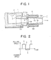
- Fig. 1 is a tundish for receiving molten steel.
- a horizontal metai mold 6 is connected through a front nozzle 3, a feed nozzle 4 and a break ring 5 to an opening 1A provided in the lower portion of a side wall of the tundish 1.
- the upstream end of the front nozzle 3 is inserted into the opening 1A of the tundish 1, and the downstream end of the front nozzle 3 is connected to the upstream end of the feed nozzle 4.
- the downstream end of the feed nozzle 4 is connected to the upstream end of the break ring 5, and the downstream end of the break ring 5 is connected to the inlet end 6A of the horizontal mold 6.
- the opening 1A of the tundish 1, the front nozzle 3, the feed nozzle 4, the break ring 5 and the horizontal mold 6 form a horizontal passage for molten steel.
- the break ring 5 has the function of forming a sure starting point of solidification of molten steel 2 introduced from the tundish 1 through the front nozzle 3, the feed nozzle 4 and the break ring 5 into the horizontal mold 6, and thus ensuring smooth withdrawal of a cast steel strand 7 from the horizontal mold 6.
- the inlet end 6A of the horizontal mold 6 is formed so as to match with the tapered outer surface 5A of the break ring 5, and the outer surface 5A of the break ring 5 comes into a liquid-tight contact with the inlet end 6A of the horizontal mold 6 by urging the break ring 5 toward the horizontal mold 6 by means of the feed nozzle 4.
- the horizontal mold 6 is made of copper or a copper alloy added with beryllium, and has therein a cooling water passage 6B. Cooling water circulates through the cooling water passage 6B to cool the horizontal mold 6.
- At least one pair of pinch rolls (not shown) and a cooling zone (not shown) are arranged following the horizontal mold 6.
- the at least one pair of pinch rolls intermittently and continuously withdraws molten steel 2 directed to the horizontal mold 6 into a cast steel strand 7 in the horizontal direction through the horizontal mold 6 by means of a plurality of cycles each comprising a pull and a push.
- the cooling zone cools the cast steel strand 7 thus withdrawn from the horizontal mold 6.
- the cast steel strand 7 is manufactured as follows. Molten steel 2 received in the tundish 1 is introduced through the front nozzle 3, the feed nozzle 4 and the break ring 5 into the horizontal mold 6. Molten steel 2 introduced into the horizontal mold 6 is intermittently and continuously withdrawn into the cast steel strand 7 in the horizontal direction through the horizontal mold 6 by the at least one pair of pinch rolls (not shown). Then, the cast steel strand 7 thus withdrawn from the horizontal mold 6 is cooled while passing through the cooling zone (not shown). The cast steel strand 7 is thus continuously cast.
- the break ring 5 has the function of forming a sure starting point of solidification of molten steel introduced into the horizontal mold 6. It is therefore important to liquid-tightly connect the outer surface 5A of the break ring 5 with the inlet end 6A of the horizontal mold 6 so as not to produce a gap therebetween. If a gap is produced between the outer surface 5A of the break ring 5 and the inlet end 6A of the horizontal mold 6, deposited metal formed by solidification of molten steel 2 penetrating into this gap during casting is caught by the gap, and this causes breakage of a solidified shell 7A of the cast steel strand 7 during pull thereof, thus imparing smooth formation of the solidified shell 7A. Defects are produced as a result on the surface of the cast steel strand 7 and may cause breakout of molten steel 2 and breakage of the break ring 5.
- GB-A-1 337 971 (corresponding to DE-A-2 100 423), on which the opening part of the main claim is based, discloses a continuous casting apparatus with a ceramic break ring.
- the ring is contained within a metal body which is clamped to the mold to keep it cool and thereby apply compressive stress to the break ring.
- the metal body also urges the break ring into contact with the mold to prevent excape of molten metal from between the break ring and the mold.
- An object of the present invention is therefore to provide a horizontal type continuous casting machine for casting molten steel into a cast steel strand, which permits an easy and liquid-tight connection of the downstream end of the break ring to the inlet end of the horizontal mold in a short period of time.
- a principal object of the present invention is to provide a horizontal type continuous casting machine for casting molten steel into a cast steel strand, which permits an easy and liquid-tight connection of the downstream end of the break ring to the inlet end of the horizontal mold in a short period of time by facilitating the fitting operation of the break ring.
- a horizontal type continuous casting machine for casting molten steel into a cast steel strand which comprises:
- the fitting operation of the break ring to the spacer ring can be performed offline, and thus the absence of a gap between the outer surface of the break ring and the inlet end of the spacer ring can be easily verified. It is therefore possible to easily connect liquid-tightly the downstream end of the break ring to the inlet end of the horizontal mold in a short period of time.
- the present invention was made on the basis of the above-mentioned finding.
- the horizontal type continuous casting machine of the present invention for casting molten steel into a cast steel strand is described below with reference to the drawings.
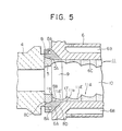
- Fig. 5 is a schematic vertical sectional view illustrating a first embodiment of the horizontal type continuous casting machine of the present invention for casting molten steel into a cast steel strand.
- 6 is a horizontal metal mold having a cooling water passage 6B.
- the horizontal mold 6 is connected through a front nozzle (not shown), a feed nozzle 4, a break ring 5 and a metal spacer ring 8 as shown in Fig. 6 to an opening provided in the lower portion of a side wall of a tundish (not shown) for receiving molten steel.
- the spacer ring 8 is made, just as the horizontal mold 6, of copper or a copper alloy added with beryllium, and has therein a cooling water passage 8A. Cooling water circulates through the cooling water passage 8A to cool the spacer ring 8.
- the inner bore 9 of the spacer ring 8 formed by the downstream side 8B of the inner surface of the spacer ring 8 has a square cross-sectional shape, just as the inner bore 10 of the horizontal mold 6 formed by the inner surface 6C of the horizontal mold 6.
- the inner bore 9 of the spacer ring 8 forms a horizontal passage for molten steel in cooperation with the inner bore 10 of the horizontal mold 6, the opening in the lower portion of the side wall of the tundish, the front nozzle, the feed nozzle 4 and the break ring 5.
- the upstream side 8C of the inner surface of the spacer ring 8 is formed so as to match with the tapered outer surface 5A of the break ring 5, and the downstream side 8D of the outer surface of the spacer ring 8 is formed so as to match with the tapered inlet end 6A of the horizontal mold 6.
- At least one pair of pinch rolls (not shown) and a cooling zone (not shown) are arranged following the horizontal mold 6.
- the at least one pair of pinch rolls intermittently and continuously withdraws molten steel directed to the spacer ring 8 and the horizontal mold 6 into a cast steel strand 11 in the horizontal direction through the horizontal mold 6 by means of a plurality of cycles each comprising one pull and one push.
- the cooling zone cools the cast steel strand 11 thus withdrawn from the horizontal mold 6.
- the cast steel strand 11 is manufactured as follows. Molten steel received in the tundish is introduced through the front nozzle (not shown), the feed nozzle 4 and the break ring 5 into the spacer ring 8 and the horizontal mold 6. Molten steel introduced into the spacer ring 8 and the horizontal mold 6 is intermittently and continuously withdrawn into the cast steel strand 11 in the horizontal direction through the horizontal mold 6 by the at least one pair of pinch rolls (not shown). Then, the cast steel strand 11 thus withdrawn from the horizontal mold 6 is cooled while passing through the cooling zone (not shown). The cast steel strand 11 is thus continuously cast.
- the metal spacer ring 8 is provided between the break ring 5 and the horizontal mold 6, it suffices to conduct the fitting operation only between the break ring 5 and the spacer ring 8 when connecting the downstream end of the break ring 5 to the inlet end 6A of the horizontal mold 6, and accordingly the fitting operation of the break ring 5 to the spacer ring 8 can be easily conducted offline. It is therefore possible to easily achieve a liquid-tight connection of the downstream end of the break ring 5 to the inlet end 6A of the horizontal mold 6 in a short period of time.
- the horizontal type continuous casting machine of the present invention for casting molten steel into a cast steel strand having square cross-section has been described.
- the present invention is applicable also to a horizontal type continuous casting machine for casting molten steel into a cast steel strand having a circular cross-section.
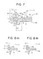
- Fig. 7 is a partial vertical sectional view illustrating an essential part of a second embodiment of the horizontal type continuous casting machine of the present invention for casting molten steel into a cast steel strand.
- the most important feature of the horizontal type continuous casting machine of the second embodiment lies in that the cross-sectional size of the inner bore of the above-mentioned metal spacer ring provided between the break ring and the horizontal mold becomes gradually smaller toward the downstream end of the break ring. More particularly, as shown in Fig.
- the maximum diameter R o of the inner bore 13 is substantially equal to the diameter of the cast steel strand 14 having a circular cross-section which is cast by the horizontal mold 6, i. e., equal to the diameter of the inner bore 15 of the horizontal mold 6, having a circular cross-section, which inner bore 15 is formed by the inner surface 6C of the horizontal mold 6.
- the spacer ring 12 of the second embodiment has therein a cooling water passage 12A.
- the downstream side 12D of the outer surface of the spacer ring 12 comes into a liquid-tight contact with the inlet end 6A of the horizontal mold 6, and the upstream side 12C of the inner surface of the spacer ring 12 comes into a liquid-tight contact with the outer surface 5A of the break ring 5.
- the inner bore 13 of the spacer ring 12 forms a horizontal passage for molten steel in cooperation with the inner bore 15 of the horizontal mold 6, the opening in the lower portion of the side of the tundish (not shown), the front nozzle (not shown), the feed nozzle (not shown) and the break ring 5.
- the other structures of the horizontal type continuous casting machine of the second embodiment are the same as those of the horizontal type continuous casting machine of the first embodiment shown in Fig. 5.
- the cross-section of the inner bore 13 of the spacer ring 12 of the second embodiment of the present invention is gradually reduced from the downstream end of the inner bore 13 toward the downstream end of the break ring 5 for the following reason.
- Fig. 2 is a descriptive view illustrating an example of one cycle comprising one pull and one push for intermittently and continuously withdrawing a cast steel strand from a horizontal mold in the horizontal direction.
- the abscissa represents time, and the ordinate indicates a pulling speed of the cast steel strand in the portion above point « 0 and a pushing speed of the cast steel strand in the portion below point «0".
- the portion «a" represents the pull period in the above-mentioned one cycle, the portion « b » the last stage of the pull period in the one cycle, and the portion « c » the push period in the one cycle.
- Figs. 3(A) to 3(C) are partial sectional views illustrating formation of a solidified shell 7A of a cast steel strand 7 in the inner bore of the horizontal mold 6 when withdrawing the cast steel strand 7 from the horizontal mold 6 of the conventional horizontal type continuous casting machine shown in Fig. 1 according to the method as mentioned above.
- Fig. 3(A) illustrates formation of the solidified shell 7A of the cast steel strand 7 during the pull period in the above-mentioned one cycle
- Fig.3(B) illustrates formation of the solidified shell 7A of the cast steel strand 7 during the last stage of the pull period in the one cycle
- Fig. 3(C) illustrates formation of the solidified shell 7A of the cast steel strand 7 during the push period in the one cycle.
- Intermittent withdrawal of the cast steel strand 7 has the effect of causing a thin solidified shell 7A formed near the break ring 5 during the pull period in one cycle to grow thick during the push period in this cycle, so as to prevent the solidified sheii 7A from breaking during the pull period in the next cycle.
- a junction face which is called a cold shut 16 is produced in the solidified shell 7A of the cast steel strand 7 between a unit shell 7A' formed during one cycle and another unit shell 7A" newly formed during the next one cycle, as shown in Figs.3(A) to 3(C).
- the cold shut 16 causes no problem so far as it is sufficiently welded, but when welding is insufficient, a crack is produced on the surface portion of the solidified shell 7A of the cast steel strand 7 in the horizontal mold 6 along the cold shut 16 during the pull period in one cycle for withdrawing the cast steel strand 7.
- a corner portion 7a of the unit shell 7A' of the solidified shell 7A is in contact with a corner of the inner bore 10 of the horizontal mold 6 (hereinafter referred to as the « corner of the inner bore 10 »), which corner of the inner bore 10 is formed by the horizontal mold 6 and the break ring 5 of the conventional horizontal type continuous casting machine.
- the corner portion 7a of the unit shell 7A' is cooled by means of both the horizontal mold 6 and the break ring 5 more remarkably than the other portion of the unit shell 7A', which is in contact only with the horizontal mold 6, during the push period in one cycle for withdrawing the cast steel strand 7, and as a result, the temperature of the corner portion 7a of the unit shell 7A' is largely reduced.
- Fig. 4 is a graph illustrating the decrease in temperature of the corner portion 7a of the unit shell 7A' of the solidified shell 7A, which is in contact with the corner of the inner bore 10 of the horizontal mold 6 of the above-mentioned conventional horizontal type continuous casting machine.
- the temperature of the corner portion 7a of the unit shell 7A' is largely reduced during a very short period of time of only from about 0.1 to about 0.3 second for which the corner portion 7a of the unit shell 7A' stays in the corner of the inner bore 10.
- the unit shell 7A" which is newly formed during the next one cycle cannot sufficiently be welded together with the corner portion 7a of the preceding unit shell 7A'.
- the corner portion 7a of the preceding unit shell 7A' can not sufficiently be welded together with the newly formed unit shell 7A".
- an insufficiently welded cold shut 16 is produced between the unit shell 7A' having the low-temperature corner portion 7a, which is formed during one cycle and the unit shell 7A", which is newly formed during the next one cycle.
- the cold shuts 16 are sufficiently welded. In this case, however, a considerable load is imposed on the withdrawal facilities of cast steel strand 7 including the pinch rolls.
- the number of the cycles is therefore practically limited within the range of from 50 to 150 cycles/minute. With the number of the cycles within this range, insufficiently welded cold shuts 16 are produced in the horizontal mold 6 for the above-mentioned reason, and thus cracks are produced along the insufficiently welded cold shuts 16.
- a corner portion 11a a of a unit shell 11A! of a solidified shell 11A of the cast steel strand 11 is in contact with a corner of the inner bore 9 of the spacer ring 8 (hereinafter referred to as the « corner of the inner bore 9 •), which corner of the inner bore 9 is formed by the spacer ring 8 and the break ring 5. Therefore, the corner portion 11 a of the unit shell 11 A' is cooled more remarkably than the other portion of the unit shell 11A' during the push period in one cycle for withdrawing the cast steel strand 11, and as a result, the temperature of the corner portion 11a of the unit shell 11A' is largely reduced. Therefore, there is a possibility of producing an insufficiently welded cold shut 17 between the unit shell 11A' having the low-temperature corner portion 11a, which is formed during one cycle and another unit shell 11A", which is newly formed during the next one cycle.
- the thickness of the wall of the spacer ring 12 near the corner of the inner bore 13 formed by the downstream side 12B of the inner surface of the spacer ring 12, is larger than the thickness of the wall of the spacer ring 8 near the corner of the inner bore 9 of the spacer ring 8 of the first embodiment of the present invention shown in Fig. 5.
- the corner portion 14a of the unit shell 14A' leaves the corner of the inner bore 13 of the spacer ring 12 during the pull period in the next cycle, the corner portion 14a of the unit shell 14A' comes into contact neither with the cooled spacer ring 12 nor with the cooled horizontal mold 6, and is surrounded by the high- temperature molten steel flowing from the tundish into the spacer ring 12 and the horizontal mold 6. Therefore, the corner portion 14a of the unit shell 14A' rapidly recovers heat from the high-temperature molten steel, and is sufficiently welded together with a unit shell 14A" which is newly formed during the next one cycle.
- a sufficiently welded cold shut 18 is produced between the unit shell 14A' and the unit shell 14A" and no crack occurs on the surface of the cast steel strand 14 along the cold shut 18.
- the above-mentioned cold shut 18, which is produced in an inclined shape, is easily crushed during rolling of the cast steel strand 14 and disappears.
- a recess caused by partial erosion may be produced during casting not only near the corner of the inner bore 9 of the spacer ring 8 in the horizontal type continuous casting machine of the first embodiment, but also near the corner of the inner bore 13 of the spacer ring 12 in the horizontal type continuous casting machine of the second embodiment, just as near the corner of the inner bore of the horizontal mold 6 in the above-mentioned conventional horizontal type continuous casting machine.
- the diameter R of the inner bore 13 of the spacer ring 12 of the second embodiment of the present invention shown in Fig. 7 becomes gradually smaller from the maximum diameter R o at the downstream end of the inner bore 13 to the minimum diameter R, at the upstream end of the inner bore 13 along a smooth concave face over the downstream side 12B of the inner surface of the spacer ring 12, which forms the inner bore 13 thereof.
- the cold shuts 18 are most sufficiently welded when the difference between the maximum diameter R o and the minimum diameter R, of the inner bore 13 is within the range of from 4 to 20 mm.
- the length e of the downstream side 12B of the inner surface of the spacer ring 12, which forms the inner bore 13 of the spacer ring 12, should preferably be up to the distance L of one pull in one cycle for withdrawing the cast steel strand 14. If the above-mentioned length is longer than the distance L of one pull in one cycle, the diameter of the tip of the solidified shell 14A of the cast steel strand 14, which sticks to the end face of a dummy bar inserted into the inner bore 15 of the horizontal mold 6 at the beginning of casting of the cast steel strand 14 becomes smaller than the diameter of the cast steel strand 14.
- the above-mentioned length should preferably be up to the range of from 5 to 30 mm.
- Fig. 8(A) is a partial vertical sectional view illustrating an essential part of a third embodiment of the horizontal type continuous casting machine of the present invention for casting molten steel into a cast steel strand.
- the diameter of the inner bore 13 of a spacer ring 12 of the third embodiment of the present invention becomes linearly and gradually smaller from the maximum diameter at the downstream end of the inner bore 13 to the minimum diameter at the upstream end of the inner bore 13 over the downstream side 12B of the inner surface of the spacer ring 12, which forms the inner bore 13 thereof.
- the other structures of the horizontal type continuous casting machine of the third embodiment shown in Fig. 8(A) are the same as those of the horizontal type continuous casting machine of the second embodiment shown in Fig. 7.
- Fig. 8(B) is a partial vertical sectional view illustrating an essential part of a fourth embodiment of the horizontal type continuous casting machine of the present invention for casting molten steel into a cast steel strand.
- the diameter of the inner bore 13 of a spacer ring 12 of the fourth embodiment of the present invention becomes gradually smaller from the maximum diameter at the downstream end of the inner bore 13 to the minimum diameter at the upstream end of the inner bore 13 along a smooth convex face over the downstream side 12B of the inner surface of the spacer ring 12, which forms the inner bore 13 thereof.
- the other structures of the horizontal type continuous casting machine'of the fourth embodiment shown in Fig. 8(B) are the same as those of the horizontal type continuous casting machine of the second embodiment shown in Fig. 7.
- the inner bore of the spacer ring has a square cross-sectional shape equal to that of the inner bore of the horizontal mold, and the dimensions of the inner bore of the square cross-section of the spacer ring are determined on the basis of a length of a side of the inner bore of the square cross-section of the spacer ring instead of the diameter R of the inner bore 13 of the circular cross-section of the spacer ring 12 for casting molten steel into the cast steel strand 14 of the circular cross-section.
- the downstream end of the break ring can easily and liquid-tightly be connected to the inlet end of the horizontal mold in a short period of time.
- the cross-section of the inner bore of the spacer ring becomes gradually smaller toward the downstream end of the break ring, it is possible to sufficiently weld the cold shuts which are produced on the surface portion of the solidified shell of the cast steel strand when intermittently and continuously withdrawing molten steel directed from the tundish to the spacer ring and the horizontal mold into a cast steel strand through the horizontal mold, thus permitting prevention of occurrence of cracks along the cold shuts.
Landscapes
- Engineering & Computer Science (AREA)
- Mechanical Engineering (AREA)
- Continuous Casting (AREA)
Claims (8)
Priority Applications (1)
| Application Number | Priority Date | Filing Date | Title |
|---|---|---|---|
| AT85309343T ATE40860T1 (de) | 1984-12-28 | 1985-12-20 | Horizontal-stranggussmaschine fuer das giessen von geschmolzenem stahl zu einem gussstahlstrang. |
Applications Claiming Priority (4)
| Application Number | Priority Date | Filing Date | Title |
|---|---|---|---|
| JP59274676A JPS61154734A (ja) | 1984-12-28 | 1984-12-28 | 水平連続鋳造機 |
| JP274676/84 | 1984-12-28 | ||
| JP27467784A JPS61154735A (ja) | 1984-12-28 | 1984-12-28 | 水平連続鋳造用鋳型のスペ−サリング |
| JP274677/84 | 1984-12-28 |
Publications (3)
| Publication Number | Publication Date |
|---|---|
| EP0187513A2 EP0187513A2 (de) | 1986-07-16 |
| EP0187513A3 EP0187513A3 (en) | 1987-05-06 |
| EP0187513B1 true EP0187513B1 (de) | 1989-02-22 |
Family
ID=26551143
Family Applications (1)
| Application Number | Title | Priority Date | Filing Date |
|---|---|---|---|
| EP85309343A Expired EP0187513B1 (de) | 1984-12-28 | 1985-12-20 | Horizontal-Stranggussmaschine für das Giessen von geschmolzenem Stahl zu einem Gussstahlstrang |
Country Status (6)
| Country | Link |
|---|---|
| US (1) | US4770229A (de) |
| EP (1) | EP0187513B1 (de) |
| CN (1) | CN1006770B (de) |
| CA (1) | CA1256668A (de) |
| DE (1) | DE3568307D1 (de) |
| ES (1) | ES8700588A1 (de) |
Cited By (1)
| Publication number | Priority date | Publication date | Assignee | Title |
|---|---|---|---|---|
| CN1042002C (zh) * | 1992-07-22 | 1999-02-10 | 曼内斯曼股份公司 | 卧式连续铸造的金属铸型 |
Families Citing this family (10)
| Publication number | Priority date | Publication date | Assignee | Title |
|---|---|---|---|---|
| EP0355940A3 (de) * | 1988-06-27 | 1991-10-30 | Chaparral Steel Company | Stranggiesskokille mit wechselbarem Einsatz |
| GB8914495D0 (en) * | 1989-06-23 | 1989-08-09 | Davy Mckee Sheffield | Continuous casting apparatus |
| US5505305A (en) * | 1992-10-21 | 1996-04-09 | Minnesota Mining And Manufacturing Company | Moisture-proof resealable pouch and container |
| USD370728S (en) | 1994-01-24 | 1996-06-11 | Minnesota Mining And Manufacturing Company | Container for orthopedic casting material |
| DE60323175D1 (de) * | 2002-03-29 | 2008-10-09 | Honda Motor Co Ltd | Knüppel, horizontal-Strangguss-Verfahren und Thixogussverfahren |
| DE102007043386B4 (de) * | 2007-09-12 | 2014-02-13 | Gautschi Engineering Gmbh | Kokille zum Stranggießen von Metall und Verfahren zum Herstellen einer derartigen Kokille |
| CN102990018B (zh) * | 2012-12-05 | 2015-07-08 | 陕西华安铸铁型材有限公司 | 一种铸铁水平连铸结晶器与保温炉缓凝型接口结构 |
| CN104043799B (zh) * | 2014-06-19 | 2016-02-10 | 无锡隆达金属材料有限公司 | 热冷型组合连续铸造工装 |
| CN104057039A (zh) * | 2014-06-19 | 2014-09-24 | 无锡隆达金属材料有限公司 | 热冷组合型水平连铸专用内冷式封炉压板 |
| CN106001469B (zh) * | 2016-07-05 | 2018-01-02 | 西安理工大学 | 一种铸铁水平连续铸造结晶器及铸铁型材的制备方法 |
Family Cites Families (8)
| Publication number | Priority date | Publication date | Assignee | Title |
|---|---|---|---|---|
| GB1182263A (en) * | 1966-05-16 | 1970-02-25 | Ashmore Benson Pease & Company | Continuous Casting. |
| GB1337971A (en) * | 1970-01-07 | 1973-11-21 | Ashmore Benson Pease & Co Ltd | Continuous casting apparatus |
| US3642058A (en) * | 1970-02-16 | 1972-02-15 | Gen Motors Corp | Mold apparatus for continuous casting |
| AT301073B (de) * | 1970-03-24 | 1972-07-15 | Adamec A | Mehrteilige stranggieszkokille |
| CH570216A5 (en) * | 1973-12-20 | 1975-12-15 | Fischer Ag Georg | Continuous casting using stepwise extrusion of the billet - in horizontal, water-cooled die with very accurate temp. control |
| JPS5122629A (ja) * | 1974-08-20 | 1976-02-23 | Nippon Steel Corp | Gokuatsukirudokohanno seizohoho |
| SU733853A1 (ru) * | 1977-11-23 | 1980-05-15 | Научно-производственное объединение "Тулачермет" | Кристаллизатор |
| DE2935170C2 (de) * | 1979-08-31 | 1983-03-24 | Proizvodstvennoe ob"edinenie Uralmaš, Sverdlovsk | Horizontale, runde Stranggießkokille |
-
1985
- 1985-12-16 CA CA000497711A patent/CA1256668A/en not_active Expired
- 1985-12-20 DE DE8585309343T patent/DE3568307D1/de not_active Expired
- 1985-12-20 EP EP85309343A patent/EP0187513B1/de not_active Expired
- 1985-12-26 ES ES550440A patent/ES8700588A1/es not_active Expired
- 1985-12-28 CN CN85109468A patent/CN1006770B/zh not_active Expired
-
1987
- 1987-06-15 US US07/063,704 patent/US4770229A/en not_active Expired - Fee Related
Cited By (1)
| Publication number | Priority date | Publication date | Assignee | Title |
|---|---|---|---|---|
| CN1042002C (zh) * | 1992-07-22 | 1999-02-10 | 曼内斯曼股份公司 | 卧式连续铸造的金属铸型 |
Also Published As
| Publication number | Publication date |
|---|---|
| US4770229A (en) | 1988-09-13 |
| CA1256668A (en) | 1989-07-04 |
| DE3568307D1 (en) | 1989-03-30 |
| CN85109468A (zh) | 1986-06-10 |
| EP0187513A2 (de) | 1986-07-16 |
| ES8700588A1 (es) | 1986-10-16 |
| EP0187513A3 (en) | 1987-05-06 |
| ES550440A0 (es) | 1986-10-16 |
| CN1006770B (zh) | 1990-02-14 |
Similar Documents
| Publication | Publication Date | Title |
|---|---|---|
| EP0187513B1 (de) | Horizontal-Stranggussmaschine für das Giessen von geschmolzenem Stahl zu einem Gussstahlstrang | |
| AU610793B2 (en) | Pouring device for dual-roll type continuous casting machines | |
| US4911226A (en) | Method and apparatus for continuously casting strip steel | |
| US3372731A (en) | Method of withdrawing the strand from a continuous casting machine | |
| CN1294950A (zh) | 用于热顶垂直连续金属浇铸的宽截面模具 | |
| JPH11216539A (ja) | 連続鋳造用ダミーバーヘッド | |
| EP0185099B2 (de) | Giessform zum waagerechten kontinuierlichen giessen von geschmolzenem metall in metallgiessstücke | |
| JP3089608B2 (ja) | ビームブランクの連続鋳造方法 | |
| US20060054300A1 (en) | Die mounting | |
| CN102009140A (zh) | 将钢水铸成铸坯的卧式连铸铸钢机 | |
| KR900003219B1 (ko) | 용강을 주강편으로 주조하기 위한 수평연속 주조기 | |
| JPS6149752A (ja) | コ−ルドシヤツト深さ低減用水平連鋳耐火物 | |
| JP3191182B2 (ja) | 高炭素合金鋼の水平連続鋳造用鋳型 | |
| CN114951575A (zh) | 一种冷镦钢连铸装置及其连铸工艺 | |
| JPH0631400A (ja) | 連続鋳造用装置 | |
| JPH072263B2 (ja) | 水平連続鋳造用鋳型のスペーサリング | |
| JPH08267181A (ja) | 連続鋳造の鋳込装置 | |
| JPH0645056B2 (ja) | 連続鋳造用モールド | |
| JPH06246395A (ja) | 水平連続鋳造設備 | |
| JPH1157946A (ja) | 連続鋳造装置 | |
| JPH04266455A (ja) | 水平連続鋳造装置のブレークリング | |
| JPH0636961B2 (ja) | 水平連続鋳造用鋳型 | |
| JPH0685979B2 (ja) | 水平連続鋳造方法及び水平連続鋳造装置用ノズル | |
| JPH09122832A (ja) | 中空ビレットの製造方法、及び装置 | |
| JPS58119443A (ja) | 鋼の湾曲型連続鋳造方法 |
Legal Events
| Date | Code | Title | Description |
|---|---|---|---|
| PUAI | Public reference made under article 153(3) epc to a published international application that has entered the european phase |
Free format text: ORIGINAL CODE: 0009012 |
|
| AK | Designated contracting states |
Kind code of ref document: A2 Designated state(s): AT BE CH DE FR GB IT LI LU |
|
| PUAL | Search report despatched |
Free format text: ORIGINAL CODE: 0009013 |
|
| AK | Designated contracting states |
Kind code of ref document: A3 Designated state(s): AT BE CH DE FR GB IT LI LU |
|
| 17P | Request for examination filed |
Effective date: 19870421 |
|
| 17Q | First examination report despatched |
Effective date: 19870918 |
|
| GRAA | (expected) grant |
Free format text: ORIGINAL CODE: 0009210 |
|
| AK | Designated contracting states |
Kind code of ref document: B1 Designated state(s): AT BE CH DE FR GB IT LI LU |
|
| REF | Corresponds to: |
Ref document number: 40860 Country of ref document: AT Date of ref document: 19890315 Kind code of ref document: T |
|
| ITF | It: translation for a ep patent filed | ||
| REF | Corresponds to: |
Ref document number: 3568307 Country of ref document: DE Date of ref document: 19890330 |
|
| ET | Fr: translation filed | ||
| PLBE | No opposition filed within time limit |
Free format text: ORIGINAL CODE: 0009261 |
|
| STAA | Information on the status of an ep patent application or granted ep patent |
Free format text: STATUS: NO OPPOSITION FILED WITHIN TIME LIMIT |
|
| 26N | No opposition filed | ||
| ITTA | It: last paid annual fee | ||
| EPTA | Lu: last paid annual fee | ||
| PGFP | Annual fee paid to national office [announced via postgrant information from national office to epo] |
Ref country code: GB Payment date: 19951211 Year of fee payment: 11 |
|
| PGFP | Annual fee paid to national office [announced via postgrant information from national office to epo] |
Ref country code: FR Payment date: 19951212 Year of fee payment: 11 |
|
| PGFP | Annual fee paid to national office [announced via postgrant information from national office to epo] |
Ref country code: AT Payment date: 19951213 Year of fee payment: 11 |
|
| PGFP | Annual fee paid to national office [announced via postgrant information from national office to epo] |
Ref country code: DE Payment date: 19951222 Year of fee payment: 11 |
|
| PGFP | Annual fee paid to national office [announced via postgrant information from national office to epo] |
Ref country code: LU Payment date: 19960101 Year of fee payment: 11 |
|
| PGFP | Annual fee paid to national office [announced via postgrant information from national office to epo] |
Ref country code: CH Payment date: 19960125 Year of fee payment: 11 |
|
| PGFP | Annual fee paid to national office [announced via postgrant information from national office to epo] |
Ref country code: BE Payment date: 19960130 Year of fee payment: 11 |
|
| PG25 | Lapsed in a contracting state [announced via postgrant information from national office to epo] |
Ref country code: LU Free format text: LAPSE BECAUSE OF NON-PAYMENT OF DUE FEES Effective date: 19961220 Ref country code: GB Effective date: 19961220 Ref country code: AT Effective date: 19961220 |
|
| PG25 | Lapsed in a contracting state [announced via postgrant information from national office to epo] |
Ref country code: LI Effective date: 19961231 Ref country code: CH Effective date: 19961231 Ref country code: BE Effective date: 19961231 |
|
| BERE | Be: lapsed |
Owner name: NIPPON KOKAN K.K. Effective date: 19961231 |
|
| GBPC | Gb: european patent ceased through non-payment of renewal fee |
Effective date: 19961220 |
|
| REG | Reference to a national code |
Ref country code: CH Ref legal event code: PL |
|
| PG25 | Lapsed in a contracting state [announced via postgrant information from national office to epo] |
Ref country code: FR Effective date: 19970829 |
|
| PG25 | Lapsed in a contracting state [announced via postgrant information from national office to epo] |
Ref country code: DE Effective date: 19970902 |
|
| REG | Reference to a national code |
Ref country code: FR Ref legal event code: ST |