EP0187561A1 - Verfahren zur Nutzung einer Lichtstrahlung mittels fluoreszierender optischer Fasern und Vorrichtungen oder Geräte die dieses Verfahren anwenden - Google Patents
Verfahren zur Nutzung einer Lichtstrahlung mittels fluoreszierender optischer Fasern und Vorrichtungen oder Geräte die dieses Verfahren anwenden Download PDFInfo
- Publication number
- EP0187561A1 EP0187561A1 EP85402295A EP85402295A EP0187561A1 EP 0187561 A1 EP0187561 A1 EP 0187561A1 EP 85402295 A EP85402295 A EP 85402295A EP 85402295 A EP85402295 A EP 85402295A EP 0187561 A1 EP0187561 A1 EP 0187561A1
- Authority
- EP
- European Patent Office
- Prior art keywords
- fiber
- light
- radiation
- fluorescent optical
- source
- Prior art date
- Legal status (The legal status is an assumption and is not a legal conclusion. Google has not performed a legal analysis and makes no representation as to the accuracy of the status listed.)
- Withdrawn
Links
- 230000005855 radiation Effects 0.000 title claims abstract description 68
- 238000000034 method Methods 0.000 title claims abstract description 41
- 230000003287 optical effect Effects 0.000 title claims description 11
- 239000013307 optical fiber Substances 0.000 claims abstract description 67
- 230000011664 signaling Effects 0.000 claims abstract description 13
- 230000005611 electricity Effects 0.000 claims abstract description 7
- 239000000835 fiber Substances 0.000 claims description 130
- 230000004907 flux Effects 0.000 claims description 28
- 230000005284 excitation Effects 0.000 claims description 17
- 239000000463 material Substances 0.000 claims description 16
- 238000010183 spectrum analysis Methods 0.000 claims description 6
- 230000010365 information processing Effects 0.000 claims description 4
- 238000012545 processing Methods 0.000 claims description 4
- 238000004804 winding Methods 0.000 claims description 4
- 230000007547 defect Effects 0.000 claims description 3
- 238000006243 chemical reaction Methods 0.000 claims description 2
- 239000011248 coating agent Substances 0.000 claims description 2
- 238000000576 coating method Methods 0.000 claims description 2
- 230000001131 transforming effect Effects 0.000 claims description 2
- 238000004519 manufacturing process Methods 0.000 abstract description 4
- 238000012544 monitoring process Methods 0.000 abstract 1
- 238000010521 absorption reaction Methods 0.000 description 12
- 239000002245 particle Substances 0.000 description 9
- 229920003023 plastic Polymers 0.000 description 8
- 239000011521 glass Substances 0.000 description 7
- VYPSYNLAJGMNEJ-UHFFFAOYSA-N Silicium dioxide Chemical compound O=[Si]=O VYPSYNLAJGMNEJ-UHFFFAOYSA-N 0.000 description 6
- 238000010586 diagram Methods 0.000 description 6
- 239000004033 plastic Substances 0.000 description 6
- 230000005540 biological transmission Effects 0.000 description 4
- 239000012141 concentrate Substances 0.000 description 4
- 230000008569 process Effects 0.000 description 4
- UHOVQNZJYSORNB-UHFFFAOYSA-N Benzene Chemical compound C1=CC=CC=C1 UHOVQNZJYSORNB-UHFFFAOYSA-N 0.000 description 3
- 230000008901 benefit Effects 0.000 description 3
- 239000000377 silicon dioxide Substances 0.000 description 3
- 239000003795 chemical substances by application Substances 0.000 description 2
- 238000001514 detection method Methods 0.000 description 2
- 125000001495 ethyl group Chemical group [H]C([H])([H])C([H])([H])* 0.000 description 2
- 229920003229 poly(methyl methacrylate) Polymers 0.000 description 2
- 239000004926 polymethyl methacrylate Substances 0.000 description 2
- 238000001228 spectrum Methods 0.000 description 2
- QKLPIYTUUFFRLV-YTEMWHBBSA-N 1,4-bis[(e)-2-(2-methylphenyl)ethenyl]benzene Chemical compound CC1=CC=CC=C1\C=C\C(C=C1)=CC=C1\C=C\C1=CC=CC=C1C QKLPIYTUUFFRLV-YTEMWHBBSA-N 0.000 description 1
- 206010001488 Aggression Diseases 0.000 description 1
- 229910052684 Cerium Inorganic materials 0.000 description 1
- 101150114843 Mgll gene Proteins 0.000 description 1
- 239000004793 Polystyrene Substances 0.000 description 1
- 230000009471 action Effects 0.000 description 1
- 230000016571 aggressive behavior Effects 0.000 description 1
- 230000003321 amplification Effects 0.000 description 1
- 150000001491 aromatic compounds Chemical class 0.000 description 1
- 125000001164 benzothiazolyl group Chemical group S1C(=NC2=C1C=CC=C2)* 0.000 description 1
- GWXLDORMOJMVQZ-UHFFFAOYSA-N cerium Chemical compound [Ce] GWXLDORMOJMVQZ-UHFFFAOYSA-N 0.000 description 1
- VYXSBFYARXAAKO-WTKGSRSZSA-N chembl402140 Chemical compound Cl.C1=2C=C(C)C(NCC)=CC=2OC2=C\C(=N/CC)C(C)=CC2=C1C1=CC=CC=C1C(=O)OCC VYXSBFYARXAAKO-WTKGSRSZSA-N 0.000 description 1
- 238000004891 communication Methods 0.000 description 1
- 239000000470 constituent Substances 0.000 description 1
- 230000023077 detection of light stimulus Effects 0.000 description 1
- 230000006866 deterioration Effects 0.000 description 1
- 238000011161 development Methods 0.000 description 1
- 230000018109 developmental process Effects 0.000 description 1
- 230000000694 effects Effects 0.000 description 1
- 238000000295 emission spectrum Methods 0.000 description 1
- 238000005516 engineering process Methods 0.000 description 1
- 238000007429 general method Methods 0.000 description 1
- 230000008570 general process Effects 0.000 description 1
- 229930195733 hydrocarbon Natural products 0.000 description 1
- 150000002430 hydrocarbons Chemical class 0.000 description 1
- 238000005286 illumination Methods 0.000 description 1
- 230000006872 improvement Effects 0.000 description 1
- 229910052500 inorganic mineral Inorganic materials 0.000 description 1
- 230000003993 interaction Effects 0.000 description 1
- 239000007788 liquid Substances 0.000 description 1
- 238000005259 measurement Methods 0.000 description 1
- 239000011707 mineral Substances 0.000 description 1
- 229910052756 noble gas Inorganic materials 0.000 description 1
- 150000002835 noble gases Chemical class 0.000 description 1
- 238000003199 nucleic acid amplification method Methods 0.000 description 1
- 230000002093 peripheral effect Effects 0.000 description 1
- 229920005553 polystyrene-acrylate Polymers 0.000 description 1
- 239000007787 solid Substances 0.000 description 1
- 239000006104 solid solution Substances 0.000 description 1
- 230000003595 spectral effect Effects 0.000 description 1
- 238000012546 transfer Methods 0.000 description 1
- 239000012780 transparent material Substances 0.000 description 1
- 238000012800 visualization Methods 0.000 description 1
Images

Classifications
-
- G—PHYSICS
- G02—OPTICS
- G02B—OPTICAL ELEMENTS, SYSTEMS OR APPARATUS
- G02B6/00—Light guides; Structural details of arrangements comprising light guides and other optical elements, e.g. couplings
- G02B6/24—Coupling light guides
- G02B6/42—Coupling light guides with opto-electronic elements
- G02B6/4298—Coupling light guides with opto-electronic elements coupling with non-coherent light sources and/or radiation detectors, e.g. lamps, incandescent bulbs, scintillation chambers
-
- F—MECHANICAL ENGINEERING; LIGHTING; HEATING; WEAPONS; BLASTING
- F24—HEATING; RANGES; VENTILATING
- F24S—SOLAR HEAT COLLECTORS; SOLAR HEAT SYSTEMS
- F24S23/00—Arrangements for concentrating solar-rays for solar heat collectors
- F24S23/12—Light guides
-
- G—PHYSICS
- G01—MEASURING; TESTING
- G01D—MEASURING NOT SPECIALLY ADAPTED FOR A SPECIFIC VARIABLE; ARRANGEMENTS FOR MEASURING TWO OR MORE VARIABLES NOT COVERED IN A SINGLE OTHER SUBCLASS; TARIFF METERING APPARATUS; MEASURING OR TESTING NOT OTHERWISE PROVIDED FOR
- G01D5/00—Mechanical means for transferring the output of a sensing member; Means for converting the output of a sensing member to another variable where the form or nature of the sensing member does not constrain the means for converting; Transducers not specially adapted for a specific variable
- G01D5/26—Mechanical means for transferring the output of a sensing member; Means for converting the output of a sensing member to another variable where the form or nature of the sensing member does not constrain the means for converting; Transducers not specially adapted for a specific variable characterised by optical transfer means, i.e. using infrared, visible, or ultraviolet light
- G01D5/32—Mechanical means for transferring the output of a sensing member; Means for converting the output of a sensing member to another variable where the form or nature of the sensing member does not constrain the means for converting; Transducers not specially adapted for a specific variable characterised by optical transfer means, i.e. using infrared, visible, or ultraviolet light with attenuation or whole or partial obturation of beams of light
- G01D5/34—Mechanical means for transferring the output of a sensing member; Means for converting the output of a sensing member to another variable where the form or nature of the sensing member does not constrain the means for converting; Transducers not specially adapted for a specific variable characterised by optical transfer means, i.e. using infrared, visible, or ultraviolet light with attenuation or whole or partial obturation of beams of light the beams of light being detected by photocells
- G01D5/353—Mechanical means for transferring the output of a sensing member; Means for converting the output of a sensing member to another variable where the form or nature of the sensing member does not constrain the means for converting; Transducers not specially adapted for a specific variable characterised by optical transfer means, i.e. using infrared, visible, or ultraviolet light with attenuation or whole or partial obturation of beams of light the beams of light being detected by photocells influencing the transmission properties of an optical fibre
- G01D5/35338—Mechanical means for transferring the output of a sensing member; Means for converting the output of a sensing member to another variable where the form or nature of the sensing member does not constrain the means for converting; Transducers not specially adapted for a specific variable characterised by optical transfer means, i.e. using infrared, visible, or ultraviolet light with attenuation or whole or partial obturation of beams of light the beams of light being detected by photocells influencing the transmission properties of an optical fibre using other arrangements than interferometer arrangements
- G01D5/35341—Sensor working in transmission
- G01D5/35348—Sensor working in transmission using stimulated emission to detect the measured quantity
-
- G—PHYSICS
- G01—MEASURING; TESTING
- G01D—MEASURING NOT SPECIALLY ADAPTED FOR A SPECIFIC VARIABLE; ARRANGEMENTS FOR MEASURING TWO OR MORE VARIABLES NOT COVERED IN A SINGLE OTHER SUBCLASS; TARIFF METERING APPARATUS; MEASURING OR TESTING NOT OTHERWISE PROVIDED FOR
- G01D5/00—Mechanical means for transferring the output of a sensing member; Means for converting the output of a sensing member to another variable where the form or nature of the sensing member does not constrain the means for converting; Transducers not specially adapted for a specific variable
- G01D5/26—Mechanical means for transferring the output of a sensing member; Means for converting the output of a sensing member to another variable where the form or nature of the sensing member does not constrain the means for converting; Transducers not specially adapted for a specific variable characterised by optical transfer means, i.e. using infrared, visible, or ultraviolet light
- G01D5/32—Mechanical means for transferring the output of a sensing member; Means for converting the output of a sensing member to another variable where the form or nature of the sensing member does not constrain the means for converting; Transducers not specially adapted for a specific variable characterised by optical transfer means, i.e. using infrared, visible, or ultraviolet light with attenuation or whole or partial obturation of beams of light
- G01D5/34—Mechanical means for transferring the output of a sensing member; Means for converting the output of a sensing member to another variable where the form or nature of the sensing member does not constrain the means for converting; Transducers not specially adapted for a specific variable characterised by optical transfer means, i.e. using infrared, visible, or ultraviolet light with attenuation or whole or partial obturation of beams of light the beams of light being detected by photocells
- G01D5/353—Mechanical means for transferring the output of a sensing member; Means for converting the output of a sensing member to another variable where the form or nature of the sensing member does not constrain the means for converting; Transducers not specially adapted for a specific variable characterised by optical transfer means, i.e. using infrared, visible, or ultraviolet light with attenuation or whole or partial obturation of beams of light the beams of light being detected by photocells influencing the transmission properties of an optical fibre
- G01D5/3537—Optical fibre sensor using a particular arrangement of the optical fibre itself
- G01D5/3538—Optical fibre sensor using a particular arrangement of the optical fibre itself using a particular type of fiber, e.g. fibre with several cores, PANDA fiber, fiber with an elliptic core or the like
-
- G—PHYSICS
- G02—OPTICS
- G02B—OPTICAL ELEMENTS, SYSTEMS OR APPARATUS
- G02B6/00—Light guides; Structural details of arrangements comprising light guides and other optical elements, e.g. couplings
- G02B6/0001—Light guides; Structural details of arrangements comprising light guides and other optical elements, e.g. couplings specially adapted for lighting devices or systems
- G02B6/0003—Light guides; Structural details of arrangements comprising light guides and other optical elements, e.g. couplings specially adapted for lighting devices or systems the light guides being doped with fluorescent agents
-
- G—PHYSICS
- G02—OPTICS
- G02B—OPTICAL ELEMENTS, SYSTEMS OR APPARATUS
- G02B6/00—Light guides; Structural details of arrangements comprising light guides and other optical elements, e.g. couplings
- G02B6/02—Optical fibres with cladding with or without a coating
-
- Y—GENERAL TAGGING OF NEW TECHNOLOGICAL DEVELOPMENTS; GENERAL TAGGING OF CROSS-SECTIONAL TECHNOLOGIES SPANNING OVER SEVERAL SECTIONS OF THE IPC; TECHNICAL SUBJECTS COVERED BY FORMER USPC CROSS-REFERENCE ART COLLECTIONS [XRACs] AND DIGESTS
- Y02—TECHNOLOGIES OR APPLICATIONS FOR MITIGATION OR ADAPTATION AGAINST CLIMATE CHANGE
- Y02E—REDUCTION OF GREENHOUSE GAS [GHG] EMISSIONS, RELATED TO ENERGY GENERATION, TRANSMISSION OR DISTRIBUTION
- Y02E10/00—Energy generation through renewable energy sources
- Y02E10/40—Solar thermal energy, e.g. solar towers
Definitions
- the present invention which relates to a method of exploiting light radiation in the air of fluorescent optical fibers and functional devices and apparatuses using this method, relates very generally to technology using optical fibers.
- Optical fibers are used, initially made of glass, then subsequently of different plastics, to conduct a light signal, introduced for example by means of focusing optics through one end of the fiber, along this fiber towards its other terminal end.
- the core of the fiber made of glass or transparent plastic, is coated in a first transparent peripheral optical sheath with a lower refractive index than that of the material used to make the core of the fiber, so that the interface between the core and this sheath is the seat of phenomena of total light reflections thus allowing the transmission of the latter along the sheath without significant loss.
- optical fibers thus used therefore require focusing towards one of their ends of the light signal to be transmitted as well as very precise geometric positioning of these ends with respect to these optical focusing means, constraints to be observed which are justified since it is in such applications transmit optical information eg for further processing for purposes of intelligible communication, or visualization on display t i on screens.
- optical information eg for further processing for purposes of intelligible communication, or visualization on display t i on screens.
- so-called "scintillating" optical fibers have also been produced, generally made of plastic materials, the core of which is doped with the aid of suitable products, so that the material of the fiber, excited by a flux of elementary particles, isotropically re-emits in the material a radiation of wavelength X greater than X ,. Part of this X-ray is lost, but a non-negligible part is captured within the fiber and propagates by internal reflection to the ends of the "scintillating" fiber where it collects.
- These fibers are intended for use in corpuscular physics in devices for detecting elementary particles and for measuring parameters linked to these particles.
- the present invention has some analogy with this very particular type of use of scintillating optical fibers, since it starts from the observation that it is possible to excite laterally a doped optical fiber, obviously devoid of mechanical protection sheath, by radiation not only of elementary physical particles as in the case of the aforementioned device, but more generally by diffuse light radiation. It therefore essentially differs therefrom by this type of light radiation used and, consequently, as will be seen below, by the applications sought and the consequent implementations proposed.
- the so-called “fluorescent” fibers are known, some types of which will be described below, which are sensitive to light radiation and more specifically also to corpuscular radiation and which, until now, have only been used in devices of the aforementioned kind of detection and measurement of quantities of physical particles.
- the invention uses such fluorescent fibers excited laterally but in interaction with light radiation, and in various new ways.
- a general object of the invention therefore is a method of exploiting at least one light radiation in at least one useful space traversed by this radiation by means of at least one fluorescent optical fiber with transparent core and sheath, characterized in that a part of such a fluorescent fiber is placed at any point in this useful space in a position such that it is capable of being excited laterally by this radiation and which at least one of the two is provided ends of the fiber, where a light signal corresponding to a lateral excitation of the fiber appears, of functional means of exploitation of this signal.
- the method is characterized in that the laterally excitable portion of fiber is liable to be subjected to the flow of a single point source and that the end of the fiber performs a binary function for signaling the state of operation or non-operation of this source.
- the method is characterized in that the laterally excitable portion of fiber is liable to be subjected to the flow of a plurality of point sources and that the fiber end provides an optical logic OR function, for signaling the non-functioning state of these sources or the functioning of at least one of them.
- the method is characterized in that the laterally excitable fiber part is wound at close turns, for example, all around and near a material light source, this fiber part thus ensuring a collection function of the luminous flux emitted by this source, and that the fiber ends perform a function of point light concentration and point emission of this concentrated light.
- the method is characterized in that a panel formed by the joining, in a cylindrical surface, of several fluorescent optical fibers whose ends are located side by side along the extreme edges of the panel, the face of the panel thus ensuring a function of collecting the luminous flux and the extreme edges of the panel thus ensuring a function of light line concentration and online emission of this light concentrated.
- the method is characterized in that one collects, this on-line emission of concentrated light using another part of fluorescent optical fiber excitable laterally by this line of emitting concentrated light , the ends of this latter fiber thus ensuring a function of second concentration of the initial flux.
- the method is characterized in that a parallel light radiation, such as solar radiation, which is then available, is used on a surface affected by this radiation.
- a parallel light radiation such as solar radiation, which is then available, is used on a surface affected by this radiation.
- a plurality of panels of the aforementioned type which the concentrated light energy is collected at the edges of these panels by a set of fluorescent optical fibers and a third fluorescent optical fiber is excited by the ends of the fibers of this set, thus ensuring a function of third concentration of the initial radiation and that the ends of this third fiber are associated with means for direct conversion of light into electricity.
- a linear light source and, opposite this source and parallel to it, a fluorescent optical fiber, and the ends of this fiber are fitted with light detectors, means for processing the information known per se being intended to process the information delivered by these detectors and thus provide indications on the variations of light laterally exciting the fiber, these variations being caused either by defects resulting from lack of material in a strip of material to be checked moving between the linear source and the fiber, or by the appearance of opaque objects in the normally free space between the linear source and the fiber.
- a polychromatic light source is exploited and a plurality of fluorescent optical fibers are subjected to the radiation from this source, each of which, by reason of its particular doping, absorbs a well-defined corresponding wavelength, so that the excitation or non-excitation of each of these fibers ensures a spectral analysis function of the radiation
- the invention also obviously relates to the many and various elementary devices allowing the practical implementation of the invention.
- the subject of the invention is therefore an elementary device characterized in that it comprises a fluorescent optical fiber, means for supporting a part of this fiber intended to place this part in a useful space crossed by at least one light radiation at exploit, and means associated with at least one end of the fiber to ensure an exploitation function of this radiation
- Another subject of the invention is an elementary device characterized in that it comprises a winding with turns close to a fluorescent optical fiber intended to form a cylindrical surface intended to surround the source of light radiation.
- Another subject of the invention is an elementary device characterized in that it comprises several fluorescent optical fibers joined laterally to each other to form a panel intended to be exposed to light radiation and the extreme edges of which constitute light line outputs concentrated.
- Another subject of the invention is an elementary device formed by the association of such a panel with a transverse fluorescent optical fiber collecting the in-line outputs of concentrated light from the panel.
- the invention also relates to devices produced by the parallel mounting of the above elementary devices.
- the invention also relates to devices produced by the series connection of the above elementary devices.
- the invention also relates to the devices constructed using the above devices for the implementation of the general method of the invention and its various applications, in particular those mentioned above.
- the subject of the invention is an apparatus for signaling the operating or non-operating state of at least one radiation source, characterized in that the means associated with the end of the fiber are signaling means mounted on a dashboard.
- Another subject of the invention is a very bright point light source, characterized in that it consists of the ends of a fiber wound with close turns around a light source.
- Another subject of the invention is a device directly transforming solar energy into electricity, characterized in that it cascaded adjoining fluorescent optical fiber panels and fibers for collecting the concentrated energy delivered on the edges of these panels , the output ends of the final fiber being associated with photovoltaic cells.
- control device characterized in that it comprises a linear light source, a fluorescent optical fiber placed opposite and parallel to this source, and photodetectors associated with the ends of this fiber, processing means. information known per se being associated with these photodetectors to interpret the variations in light received by the fiber.
- Another subject of the invention is an apparatus for spectral analysis of polychromatic radiation, characterized in that it comprises a plurality of fluorescent optical fibers doped in different ways and consequently absorbing radiation of different wavelengths, means information processing known per se being associated with the output signals of the different fibers to perform this spectral analysis.
- FIG. 1 very schematically illustrates the usual way of using optical fibers which consists in injecting the light flux 1 from a source 2, by means of a focusing optic 3 for example, through the input face 4 of an optical fiber 5. After transport, the light energy is available on the exit face 6 of the fiber.
- the conformation of the input light signal therefore requires the use of precise optical means 3 and the precise positioning of these means relative to the input face 4 of the optical fiber.
- the invention which also aims to treat light radiation, but for other applications, aims to be free from these constraints.
- FIG. 2 This figure represents the only part of a known physics apparatus which relates by analogy to the present invention.
- the impact of an elementary particle shown diagrammatically by the arrow 7, on a scintillating plate 8 generates, by scintillation within the material of the plate 8, a light emission which remains captured inside the plate and arrives, following successive total reflections, on the lateral edges of the plate where it delivers a light signal.
- One edge of the plate 8 is attached over its entire length to a scintillating optical fiber 9 which, in turn, is excited by this signal and this excitation causes the delivery of a second light signal at one end 10 of the fiber 9.
- Fluorescence is the phenomenon by which matter excited by light radiation of wavelength X ,, isotropically re-emits radiation of wavelength X, greater than X,.
- the absorption bands t i on and retransmission are characteristic of the material used, as well as the fluorescence yield. Matter in all its forms can be the seat of fluorescence, whether it is gaseous (noble gases such as Kr, A or Ne), liquid (hydrocarbons, aromatic compounds, ...) or solid (crystalline like certain cerium glasses) .
- the present invention relates more particularly to the fluorescence of transparent plastic materials doped with high-yield fluorescent products, thus forming solid solutions.
- Optical fibers for their part, the subject of wide developments today, consist of a transparent central part with a high refractive index covered with a thin layer also transparent with a lower index. Its function is to protect from various external aggressions the surface of the heart on which the internal reflections of light will occur.
- optical fibers are made of glass or silica, but plastic fibers are also booming due to the simplicity of their manufacture and their low cost.
- Plastic fibers also have the great advantage of being easily doped with scintillating or fluorescent materials, as mentioned above. This is also possible, although less easy, for glass or silica fibers, which are therefore usable for all the applications described below.
- Part is lost and comes out of the fiber, but a non-negligible part is captured within the fiber, and propagates by internal reflection to the end where there is therefore a light flux at wavelength ⁇ ,.
- a fiber 2 m long, with a diameter of 1 mm such as those produced by the applicant, would concentrate the flux which it absorbs around the wavelength X, by a factor of 60 at each of its ends, by means of a spectral shift ⁇ 1 ⁇ ⁇ 2 . hence the interest in small diameter fibers. (provided that the transparency properties are preserved, as well as a satisfactory absorption of the incident flux), and that cascading structures, where one benefits at each stage from the concentration, are conceivable as will be illustrated below .
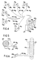
- FIG. 4 A first and simplest application of the method of the invention is illustrated diagrammatically in FIG. 4. It relates to the control from a single dashboard of the operating state of different light sources located in separate locations. . It can be a question of controlling the lighting of rooms in a set of rooms, or even checking the proper functioning of light sources fitted to an automobile.
- This first application of the invention therefore only implements a function for detecting light radiation, possibly for detecting several distinct light rays in parallel.
- a coating acting as a mirror is applied to the other unused end of the fiber.
- a second application of the method of the invention aims to have a very bright point light source from a low-light point source placed at a distance.
- FIG. 5 This application is schematically represented in FIG. 5.
- this lamp 1 1 .7 is completely surrounded by a winding 22 of a fluorescent optical fiber near to 14.7 turns.
- the fiber 14.7 around the lamp 11.7 is shown using a simple drawing line. The two strands joined together 14-19.7 of this fiber will remotely be plugged into a support shown diagrammatically at 21 which, thus fed, constitutes a very bright point light source by the outlet ends 20.7 of this fiber.
- This second application of the invention implements a collection and concentration function of the maximum light emitted by a light source with non-parallel flux.
- FIG. 6 illustrates the same application, but using the light radiation emitted by a fluorescent tube.
- the same reference numbers identify in FIGS. 5 and 6 the same or analogous elements.
- This collection function allows a relatively high efficiency, possibly approaching 20% of collection, of the light radiation emitted by the starting light source, and this without centering or precise positioning of the winding 22 relative to the source 11.7.
- a third application of the invention relates to the collection and concentration of light radiation using devices using the method of the invention, but has a parallel mounting of fluorescent optical fibers to form panels.
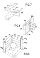
- FIG. 7 schematically illustrates the state of the prior art closest to this application.
- This figure illustrates the known process consisting in exposing a thick plate of a transparent material (mineral or organic glass), doped with the aid of an appropriate fluorescent product, to solar radiation schematized by the two sets of orthogonal arrows 23. A part of the flow is absorbed and then re-emitted isotropically by fluorescence.
- a fraction of the re-emitted light energy is confined inside the plate, and it propagates by internal reflections up to the slices where it is available for these sensors of the photovoltaic cell type for example, as represented by the path of the ray. 23.
- FIG. 8 This new application is illustrated - diagrammatically in FIG. 8.
- a parallel light radiation such as solar radiation
- - shown diagrammatically by the two sets of orthogonal arrows 23 strike laterally a set of six fluorescent optical fibers 14.8 placed side by side to each other by generators contained in the same plane.
- the light entering laterally in these fibers is channeled towards the ends 20.8 of the joined fibers and the reflections inside the material are less numerous than in the case of FIG. 7, and with a coefficient close to 100%.
- an elementary panel 24 of adjoining fluorescent optical fibers making it possible to deliver on its upper 25 and lower 26 edges concentrated light signals resulting from the collection and concentration of the incident light fluxes 23.
- Such panels allow the cascade mounting of two stages of collection and concentration of light flux, as now shown in FIG. 9 relating to yet another application of the method of the invention.
- FIG 9 there is shown in perspective an incandescent lamp 2 enclosed in a box consisting of four panels 24 of fluorescent optical fibers of the type shown in Figure 8, only two of which have been drawn.
- the panels 24 collect and concentrate on their edges 25 and 26 the flux emitted by the lamp 2.
- Vertical fluorescent optical fibers 14.9 are arranged at the four junction edges of the four panels 24 and collect in their turn, in a second stage, the signals luminous available on edges 25 and 26 and concentrate them at their ends 20.9.
- the box thus constituted will allow the fraction of the spectrum emitted by the lamp to pass, which is not absorbed by the fluorescent optical fibers of the panels 24.
- This device of FIG. 9 therefore constitutes a seemingly conventional luminaire, but providing, above all, a high concentration of the light absorbed by the fibers of the panels of the box on four additional channels made up of the four vertical optical fibers 14.9.
- Yet another application of the invention relates to the collection and concentration of several stages of parallel light fluxes such as solar radiation.
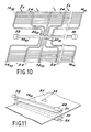
- FIG. 10 schematically illustrates in perspective this other application.
- the incident solar flux E falls on the flat device, placed on the ground, of FIG. 10.
- This device comprises panels 24 made up of shoulder-mounted fluorescent optical fibers, such as that of FIG. 8, and the ends of these panels excite fibers 14.10 arranged opposite these ends and whose ends 20.10 are joined in lines to be opposite a terminal fiber 14.10.1 providing a third collection-concentration stage, similar to that shown in FIG. 9.
- the output ends of the terminal fiber 14.10.1 can be connected to converters such as photovoltaic cells 32 to obtain electricity directly.
- An apparatus such as that shown in FIG. 10 can be installed on the roofs of dwellings.
- Yet another application of the invention relates to an apparatus for detecting holes in wide strips running in front of a transverse strip control line.
- one or more light sources obscured by the strip are arranged along this line.
- This prior art is hardly suitable for controlling large bandwidths, because it involves a very high number of photodiodes.
- This device comprises transversely to the strip 27 to be checked, a fluorescent optical fiber 14.11, the two ends of which are connected to two photodiodes 28.
- a linear light source such than a fluorescent tube 29.
- simple optics 30 and 31 respectively focus and concentrate the light flux emitted by the tube 29 and received by the fiber 14.11.
- the signals received by the diodes 28 can be processed to define the location and extent of these faults.
- a fluorescent optical fiber has well-defined absorption and re-emission spectra. Consequently, according to the invention, the implementation of the method described above, for certain applications, also provides a spectrum selection function as has been mentioned for the luminaire illustrated in FIG. 9.
- fibers whose core is polystyrene or polymethyl methacrylate will be used, the latter being known by the abbreviation of PMMA.
- this base will be mixed at 100 mgll with bis-MSB whose formula is
- the absorption wavelength of this thus doped fiber is 460 nm in blue-green and its re-emission wavelength is 540 nm in green-yellow.
- the absorption wavelength of this thus doped fiber is 530 nm in the green, and its re-emission wavelength is 585 nm in the red.
Landscapes
- Physics & Mathematics (AREA)
- General Physics & Mathematics (AREA)
- Engineering & Computer Science (AREA)
- Optics & Photonics (AREA)
- Sustainable Energy (AREA)
- Sustainable Development (AREA)
- Life Sciences & Earth Sciences (AREA)
- Thermal Sciences (AREA)
- Chemical & Material Sciences (AREA)
- Combustion & Propulsion (AREA)
- Mechanical Engineering (AREA)
- General Engineering & Computer Science (AREA)
- Light Guides In General And Applications Therefor (AREA)
- Investigating, Analyzing Materials By Fluorescence Or Luminescence (AREA)
Applications Claiming Priority (2)
| Application Number | Priority Date | Filing Date | Title |
|---|---|---|---|
| FR8418831A FR2574564B1 (fr) | 1984-12-10 | 1984-12-10 | Procede d'exploitation d'un rayonnement lumineux a l'aide de fibres optiques fluorescentes, et dispositifs et appareils fonctionnels utilisant ce procede |
| FR8418831 | 1984-12-10 |
Publications (1)
| Publication Number | Publication Date |
|---|---|
| EP0187561A1 true EP0187561A1 (de) | 1986-07-16 |
Family
ID=9310418
Family Applications (1)
| Application Number | Title | Priority Date | Filing Date |
|---|---|---|---|
| EP85402295A Withdrawn EP0187561A1 (de) | 1984-12-10 | 1985-11-25 | Verfahren zur Nutzung einer Lichtstrahlung mittels fluoreszierender optischer Fasern und Vorrichtungen oder Geräte die dieses Verfahren anwenden |
Country Status (3)
| Country | Link |
|---|---|
| US (1) | US4753512A (de) |
| EP (1) | EP0187561A1 (de) |
| FR (1) | FR2574564B1 (de) |
Cited By (3)
| Publication number | Priority date | Publication date | Assignee | Title |
|---|---|---|---|---|
| FR2653253A1 (fr) * | 1989-10-16 | 1991-04-19 | Commissariat Energie Atomique | Dispositif de signalisation lumineuse a contraste autoregule. |
| WO1995006931A1 (fr) * | 1993-09-03 | 1995-03-09 | Commissariat A L'energie Atomique | Dispositif de visualisation a conversion de faisceau laser en lumiere visible et incoherente |
| WO2000007039A1 (en) * | 1998-07-29 | 2000-02-10 | The Court Of Napier University | Displays |
Families Citing this family (9)
| Publication number | Priority date | Publication date | Assignee | Title |
|---|---|---|---|---|
| US4812013A (en) * | 1984-12-10 | 1989-03-14 | Claude Aurouet | Process for utilizing light radiation with the aid of fluorescent optical fibres and functional devices and apparatus using said process |
| FR2614112B1 (fr) * | 1987-04-14 | 1991-10-11 | Electricite De France | Capteur de lumiere a fibre optique |
| FR2634031A1 (fr) * | 1988-07-05 | 1990-01-12 | Commissariat Energie Atomique | Dispositif de multiplexage en longueur d'onde utilisant une fibre optique |
| JP3019274B2 (ja) * | 1991-09-04 | 2000-03-13 | 東京電力株式会社 | 光検出装置 |
| US5325855A (en) * | 1992-08-07 | 1994-07-05 | Memorial Hospital For Cancer And Allied Diseases | Flexible intraoperative radiation imaging camera |
| FR2763700B1 (fr) * | 1997-05-23 | 1999-07-30 | Thomson Tubes Electroniques | Dispositif de mesure d'exposition d'un detecteur d'image a l'etat solide soumis a un rayonnement ionisant et detecteur d'image equipe d'un tel dispositif de mesure |
| EP1016881B1 (de) * | 1998-12-28 | 2005-12-21 | Kabushiki Kaisha Toshiba | Strahlungsdetektoreinrichtung |
| US7146084B2 (en) * | 2003-06-16 | 2006-12-05 | Cmc Electronics, Inc. | Fiber optic light source for display devices |
| CN119251967A (zh) * | 2024-12-05 | 2025-01-03 | 山东电工时代能源科技有限公司 | 一种储能电站锂离子电池的火灾预警系统及方法 |
Citations (9)
| Publication number | Priority date | Publication date | Assignee | Title |
|---|---|---|---|---|
| US3274392A (en) * | 1963-08-22 | 1966-09-20 | Mc Graw Edison Co | Light collector for photosensitive luminaire control |
| US3317738A (en) * | 1963-12-12 | 1967-05-02 | Licentia Gmbh | Photoelectric scanning arrangement using light conducting rod with fluorescent portion |
| US3567985A (en) * | 1962-07-26 | 1971-03-02 | David M Goodman | X-ray and ultraviolet detectors for beam-index and heaterless cathode ray tubes |
| US3569933A (en) * | 1969-07-29 | 1971-03-09 | Amp Inc | Signalling system with indicating means |
| GB1274128A (en) * | 1970-03-19 | 1972-05-10 | Inst Kib Akademii Nauk Gruzins | Optical fibre |
| US3934148A (en) * | 1974-05-28 | 1976-01-20 | Collins William O | Fluorescent plastic controlled direction lamp |
| FR2365814A1 (fr) * | 1976-09-28 | 1978-04-21 | Jenaer Glaswerk Schott & Gen | Systeme a fibres optiques pour dispositifs de signalisation |
| EP0022198A1 (de) * | 1979-07-04 | 1981-01-14 | Siemens Aktiengesellschaft | Anordnung zur Helligkeitsverstärkung von passiven Anzeigevorrichtungen |
| EP0074807A1 (de) * | 1981-09-10 | 1983-03-23 | The Secretary of State for Defence in Her Britannic Majesty's Government of the United Kingdom of Great Britain and | Fluoreszente optische Konzentratorvorrichtungen |
Family Cites Families (4)
| Publication number | Priority date | Publication date | Assignee | Title |
|---|---|---|---|---|
| US4023887A (en) * | 1972-10-30 | 1977-05-17 | General Optimation, Inc. | Optical communication, switching and control apparatus and systems and modular electro-optical logic circuits, and applications thereof |
| US4425907A (en) * | 1980-09-25 | 1984-01-17 | Exxon Research And Engineering Co. | Reflector-coupled fluorescent solar collector |
| JPS5776466A (en) * | 1980-10-29 | 1982-05-13 | Toshiba Corp | Radiation detector |
| US4403826A (en) * | 1981-03-23 | 1983-09-13 | Bell Telephone Laboratories, Incorporated | Ultraviolet radiation detector |
-
1984
- 1984-12-10 FR FR8418831A patent/FR2574564B1/fr not_active Expired
-
1985
- 1985-11-25 EP EP85402295A patent/EP0187561A1/de not_active Withdrawn
- 1985-12-09 US US06/806,610 patent/US4753512A/en not_active Expired - Fee Related
Patent Citations (9)
| Publication number | Priority date | Publication date | Assignee | Title |
|---|---|---|---|---|
| US3567985A (en) * | 1962-07-26 | 1971-03-02 | David M Goodman | X-ray and ultraviolet detectors for beam-index and heaterless cathode ray tubes |
| US3274392A (en) * | 1963-08-22 | 1966-09-20 | Mc Graw Edison Co | Light collector for photosensitive luminaire control |
| US3317738A (en) * | 1963-12-12 | 1967-05-02 | Licentia Gmbh | Photoelectric scanning arrangement using light conducting rod with fluorescent portion |
| US3569933A (en) * | 1969-07-29 | 1971-03-09 | Amp Inc | Signalling system with indicating means |
| GB1274128A (en) * | 1970-03-19 | 1972-05-10 | Inst Kib Akademii Nauk Gruzins | Optical fibre |
| US3934148A (en) * | 1974-05-28 | 1976-01-20 | Collins William O | Fluorescent plastic controlled direction lamp |
| FR2365814A1 (fr) * | 1976-09-28 | 1978-04-21 | Jenaer Glaswerk Schott & Gen | Systeme a fibres optiques pour dispositifs de signalisation |
| EP0022198A1 (de) * | 1979-07-04 | 1981-01-14 | Siemens Aktiengesellschaft | Anordnung zur Helligkeitsverstärkung von passiven Anzeigevorrichtungen |
| EP0074807A1 (de) * | 1981-09-10 | 1983-03-23 | The Secretary of State for Defence in Her Britannic Majesty's Government of the United Kingdom of Great Britain and | Fluoreszente optische Konzentratorvorrichtungen |
Cited By (7)
| Publication number | Priority date | Publication date | Assignee | Title |
|---|---|---|---|---|
| FR2653253A1 (fr) * | 1989-10-16 | 1991-04-19 | Commissariat Energie Atomique | Dispositif de signalisation lumineuse a contraste autoregule. |
| WO1995006931A1 (fr) * | 1993-09-03 | 1995-03-09 | Commissariat A L'energie Atomique | Dispositif de visualisation a conversion de faisceau laser en lumiere visible et incoherente |
| FR2709567A1 (fr) * | 1993-09-03 | 1995-03-10 | Commissariat Energie Atomique | Dispositif de visualisation à conversion de faisceau laser en lumière visible et incohérente. |
| US5606634A (en) * | 1993-09-03 | 1997-02-25 | Commissariat A L'energie Atomique | Display unit for conversion of a laser beam into visible and incoherent light |
| WO2000007039A1 (en) * | 1998-07-29 | 2000-02-10 | The Court Of Napier University | Displays |
| GB2357515A (en) * | 1998-07-29 | 2001-06-27 | Univ Napier | Displays |
| GB2357515B (en) * | 1998-07-29 | 2003-04-09 | Univ Napier | Displays |
Also Published As
| Publication number | Publication date |
|---|---|
| US4753512A (en) | 1988-06-28 |
| FR2574564A1 (fr) | 1986-06-13 |
| FR2574564B1 (fr) | 1988-02-05 |
Similar Documents
| Publication | Publication Date | Title |
|---|---|---|
| EP0187561A1 (de) | Verfahren zur Nutzung einer Lichtstrahlung mittels fluoreszierender optischer Fasern und Vorrichtungen oder Geräte die dieses Verfahren anwenden | |
| WO2003050887A2 (fr) | Dispositif d'emission de lumiere et procede de fabrication d'un tel dispositif | |
| FR2581768A1 (fr) | Composant optoelectrique bidirectionnel formant coupleur optique | |
| FR2792461A1 (fr) | Generateurs photovoltaiques a cascade lumineuse et variation de flux elecromomagnetique | |
| FR2657694A1 (fr) | Detecteur de scintillations en mosauique a deux dimensions. | |
| EP3563140A1 (de) | Vorrichtung zur detektion von gas oder partikeln und verfahren zur herstellung solch einer vorrichtung | |
| US4812013A (en) | Process for utilizing light radiation with the aid of fluorescent optical fibres and functional devices and apparatus using said process | |
| EP2919037A1 (de) | Optimierungsverfahren der Sammlung von Photonen in Szintillationskristallen, entsprechender Kristall und entsprechende Anwendungen | |
| EP0319080B1 (de) | Röntgenstrahl-Bildverstärkerröhre | |
| FR3075979A1 (fr) | Scintillateur plastique nanostructure | |
| WO2015185855A1 (fr) | Dispositif photovoltaïque et procédé de fabrication associé | |
| EP3968066A1 (de) | Wellenleiter, der eine optische multimode-faser umfasst und die geführten moden räumlich konzentrieren kann | |
| FR2613832A1 (fr) | Procede et appareil de mesure de temperature par fibres optiques | |
| EP3144589B1 (de) | Leuchtvorrichtung, insbesondere für kraftfahrzeug, und scheinwerfer, der eine solche vorrichtung umfasst | |
| FR3151075A1 (fr) | Dispositif d’émission lumineuse amélioré comprenant un concentrateur de lumière luminescent | |
| FR3144432A1 (fr) | Dispositif d’émission de lumière avec une extraction améliorée | |
| FR2792460A1 (fr) | Generateurs photovoltaiques a cascade lumineuse et variation de flux electromagnetique | |
| EP3936763A1 (de) | Lumineszenzkonzentrator | |
| FR2697352A1 (fr) | Concentrateur d'énergie électromagnétique à changement de fréquence constituant entre autre une iode électromagnétique. | |
| WO2025127995A1 (en) | Light concentrator and method of forming the same | |
| FR2637088A1 (fr) | Fibres optiques scintillantes de faible diametre et detecteur comportant de telles fibres | |
| EP4567475A1 (de) | Neutronendetektor mit reflektiver optischer hohlraumfissionskammer und kammergekoppeltem detektionskopf mit optischer linse und einem optischen faserkoppler | |
| EP4391572A1 (de) | Digitaler detektor mit einem lichtgenerator zur optischen löschung | |
| FR3153941A1 (fr) | Ensemble de concentrateurs de lumière luminescents, Dispositif d’émission lumineuse et Méthode pour générer un faisceau de sortie avec un spectre large | |
| FR2572496A1 (fr) | Lampe indicatrice |
Legal Events
| Date | Code | Title | Description |
|---|---|---|---|
| PUAI | Public reference made under article 153(3) epc to a published international application that has entered the european phase |
Free format text: ORIGINAL CODE: 0009012 |
|
| AK | Designated contracting states |
Kind code of ref document: A1 Designated state(s): DE GB SE |
|
| 17P | Request for examination filed |
Effective date: 19861218 |
|
| 17Q | First examination report despatched |
Effective date: 19880210 |
|
| RAP1 | Party data changed (applicant data changed or rights of an application transferred) |
Owner name: COMMISSARIAT A L'ENERGIE ATOMIQUE |
|
| STAA | Information on the status of an ep patent application or granted ep patent |
Free format text: STATUS: THE APPLICATION IS DEEMED TO BE WITHDRAWN |
|
| 18D | Application deemed to be withdrawn |
Effective date: 19910411 |
|
| RIN1 | Information on inventor provided before grant (corrected) |
Inventor name: THEVENIN, JEAN-CLAUDE Inventor name: MEYER, JOAO Inventor name: CAVAN, JEAN-CLAUDE Inventor name: CALVET, JEAN Inventor name: BOURDINAUD, MICHEL Inventor name: BLUMENFELD, HENRY Inventor name: AUROUET, CLAUDE |