EP0187910A2 - Méthode pour calibrer un capteur électronique de position - Google Patents
Méthode pour calibrer un capteur électronique de position Download PDFInfo
- Publication number
- EP0187910A2 EP0187910A2 EP85114314A EP85114314A EP0187910A2 EP 0187910 A2 EP0187910 A2 EP 0187910A2 EP 85114314 A EP85114314 A EP 85114314A EP 85114314 A EP85114314 A EP 85114314A EP 0187910 A2 EP0187910 A2 EP 0187910A2
- Authority
- EP
- European Patent Office
- Prior art keywords
- sensors
- voltage
- evaluation device
- sensor
- movable part
- Prior art date
- Legal status (The legal status is an assumption and is not a legal conclusion. Google has not performed a legal analysis and makes no representation as to the accuracy of the status listed.)
- Granted
Links
Images

Classifications
-
- G—PHYSICS
- G01—MEASURING; TESTING
- G01B—MEASURING LENGTH, THICKNESS OR SIMILAR LINEAR DIMENSIONS; MEASURING ANGLES; MEASURING AREAS; MEASURING IRREGULARITIES OF SURFACES OR CONTOURS
- G01B7/00—Measuring arrangements characterised by the use of electric or magnetic techniques
- G01B7/003—Measuring arrangements characterised by the use of electric or magnetic techniques for measuring position, not involving coordinate determination
-
- G—PHYSICS
- G01—MEASURING; TESTING
- G01D—MEASURING NOT SPECIALLY ADAPTED FOR A SPECIFIC VARIABLE; ARRANGEMENTS FOR MEASURING TWO OR MORE VARIABLES NOT COVERED IN A SINGLE OTHER SUBCLASS; TARIFF METERING APPARATUS; MEASURING OR TESTING NOT OTHERWISE PROVIDED FOR
- G01D18/00—Testing or calibrating apparatus or arrangements provided for in groups G01D1/00 - G01D15/00
- G01D18/008—Testing or calibrating apparatus or arrangements provided for in groups G01D1/00 - G01D15/00 with calibration coefficients stored in memory
-
- G—PHYSICS
- G01—MEASURING; TESTING
- G01R—MEASURING ELECTRIC VARIABLES; MEASURING MAGNETIC VARIABLES
- G01R35/00—Testing or calibrating of apparatus covered by the other groups of this subclass
- G01R35/005—Calibrating; Standards or reference devices, e.g. voltage or resistance standards, "golden" references
Definitions
- the invention relates to a method for calibrating a device for contactless position measurement according to the preamble of the claim.
- Such a device is known from DE-OS 32 44 891.
- the respective voltage values of the individually queried sensors are assigned to the predetermined magnet position over the entire effective range of the magnet.
- Each magnet position measured in units of length, thus receives an assigned voltage distribution, hereinafter referred to as "position voltage distribution". Every time the magnet shifts, a new position voltage distribution results.
- This position voltage distribution is unambiguous, ie exactly one position voltage distribution corresponds to each magnet position value and vice versa exactly one magnet position value corresponds to a position voltage distribution.
- the characteristic position voltage distributions can be assigned and saved to the individual magnet positions in a calibration process.
- a magnet that is connected to a moving part according to this method can thus serve as a position indicator for a moving part serve.
- the object of the invention is therefore to design the method of the type mentioned in the introduction in such a way that these difficulties are avoided and a clear characteristic of the position voltage distribution is obtained.
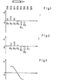
- the sensor characteristic shown as voltage as a function of the magnet position in relation to the sensor, has the typical course shown in Figure 3. If the magnet is positioned above the sensor with a uniform, uniform magnetic field distribution, the sensor emits a characteristic voltage value, which is to be given the value 0 here by appropriate voltage presetting. If one of the poles of the magnet approaches this sensor position, there is an initially linear rise or fall in the voltage. Depending on the strength of the magnetic field and the distance of the magnetic field from the sensor, this line-are run changes into an alinear curve until the maximum output voltage due to the influence of the magnetic field is reached.
- This described method can be modified by storing specific voltage ratios for a constant step size of the position shift of the magnet, which means that length units found with specific length units should not be saved as with constant voltage ratios as above. With this method there would be the advantage that an arbitrarily exact numerical ratio of the voltage values can be determined for a certain step size of the calibration system.
- a system can be built which can be used for determining the position of longitudinally displaceable magnets. Magnets, which are brought to the sensor row in any position, act on magnetically sensitive sensors, which according to OS 32 44 891 are queried for their voltage values. According to the invention, however, such signal values from sensors that are subject to a change in sign are used for precise position determination. The ratios of voltage values of the sensors are determined and from this the exact position of the magnet is determined by means of suitable interpolation methods.
- Figure 3 shows the characteristics of a sensor, for example sensor 4. If the north pole is approached to sensor S4, the voltage value of the sensor will become more negative from the 0 position, correspondingly more positive when the south pole approaches. In the. A linear curve can be expected near the 0 position of the sensor.
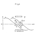
- Figure 4 shows two characteristic curves for neighboring sensors n and n + 1. Give the Sen-. sensor voltage signals with the voltage output value 0, the sensors receive the position value Pn or Pn + 1. If the magnet is moved between the two sensors, certain voltage relationships are set at the sensors, which are shown in Figure 4 with corresponding breaks. When certain numerical ratios of the voltage signals are reached, corresponding position values, designated Pna-Pnc, are stored. If the sensors give these signal ratios during later measurements, the corresponding positions can be determined from them, as shown in Figure 4.
- Figure 5 shows how the relationships appear when the voltage ratio a, b corresponds exactly to a calibration ratio, so that the calibration position Pc results.
- the virtual characteristic curve of a fictitious r Sensor is pulled, which supplies the voltage value 0 exactly in this position.
- Figure 6 shows how voltage relationships a, b exist that do not correspond to a calibration point Pc.
- the voltage relationships correspond to the unknown position value Px of the magnet.
- Such a position Px is enclosed by a right-hand calibration position or by a left-hand calibration position.
- the value Px can be determined from the voltage relationships for this right-hand or left-hand calibration position using an interpolation method.
Landscapes
- Physics & Mathematics (AREA)
- General Physics & Mathematics (AREA)
- Measurement Of Length, Angles, Or The Like Using Electric Or Magnetic Means (AREA)
Applications Claiming Priority (2)
| Application Number | Priority Date | Filing Date | Title |
|---|---|---|---|
| DE3443176A DE3443176C1 (de) | 1984-11-27 | 1984-11-27 | Verfahren zur Kalibrierung eines elektronischen Positionsgebers |
| DE3443176 | 1984-11-27 |
Publications (3)
| Publication Number | Publication Date |
|---|---|
| EP0187910A2 true EP0187910A2 (fr) | 1986-07-23 |
| EP0187910A3 EP0187910A3 (en) | 1987-03-11 |
| EP0187910B1 EP0187910B1 (fr) | 1990-09-12 |
Family
ID=6251250
Family Applications (1)
| Application Number | Title | Priority Date | Filing Date |
|---|---|---|---|
| EP85114314A Expired - Lifetime EP0187910B1 (fr) | 1984-11-27 | 1985-11-11 | Méthode pour calibrer un capteur électronique de position |
Country Status (4)
| Country | Link |
|---|---|
| US (1) | US4698996A (fr) |
| EP (1) | EP0187910B1 (fr) |
| JP (1) | JPS61132802A (fr) |
| DE (1) | DE3443176C1 (fr) |
Cited By (1)
| Publication number | Priority date | Publication date | Assignee | Title |
|---|---|---|---|---|
| JP2002511571A (ja) * | 1998-04-14 | 2002-04-16 | ハネウエル・インコーポレーテッド | センサの非線形領域に対する補正機能を具備した位置検出装置 |
Families Citing this family (39)
| Publication number | Priority date | Publication date | Assignee | Title |
|---|---|---|---|---|
| DE3611469A1 (de) * | 1986-04-05 | 1987-10-08 | Bosch Gmbh Robert | Vorrichtung und verfahren zur beruehrungslosen positionsmessung |
| US4850232A (en) * | 1988-04-15 | 1989-07-25 | Eastman Kodak Company | System for measuring the dimensions of a workpiece |
| DE3829279A1 (de) * | 1988-08-30 | 1990-03-01 | Angewandte Digital Elektronik | Verlaengerung der messstrecke eines positionsgebers |
| US5038305A (en) * | 1989-02-27 | 1991-08-06 | Microfast Controls Corp. | Programmable controller linear transducer input modules |
| GB9112397D0 (en) * | 1991-06-10 | 1991-07-31 | Infrared Eng | Apparatus for sampling a material travelling past a sampling region |
| DE4201721C2 (de) * | 1992-01-23 | 1994-06-30 | Bosch Gmbh Robert | Berührungsloser Geber |
| DE4210934C1 (fr) * | 1992-04-02 | 1993-07-15 | Robert Bosch Gmbh, 7000 Stuttgart, De | |
| US5589769A (en) * | 1994-09-30 | 1996-12-31 | Honeywell Inc. | Position detection apparatus including a circuit for receiving a plurality of output signal values and fitting the output signal values to a curve |
| JPH11513099A (ja) * | 1996-06-21 | 1999-11-09 | アウトボード・マリーン・コーポレーション | 機関制御に用いられる位置センサーを自動調整する方法及び装置 |
| US6191507B1 (en) * | 1997-05-02 | 2001-02-20 | Ats Automation Tooling Systems Inc. | Modular conveyor system having multiple moving elements under independent control |
| DE19726335C2 (de) | 1997-06-20 | 2000-03-02 | Angewandte Digital Elektronik | Chipkarte mit mindestens zwei Spulenanordnungen zur Übertragung von Daten und/oder Energie |
| EP1046839B1 (fr) | 1999-04-20 | 2003-07-16 | Siemens Aktiengesellschaft | Procédé de calibration d'un capteur de position |
| DE19938110A1 (de) * | 1999-08-12 | 2001-02-22 | Siemens Ag | Elektronisches Steuergerät für ein Kraftfahrzeug-Automatikgetriebe und Verfahren zum Abgleichen eines Positionserkennungsensors in einem elektronischen Steuergerät für ein Kraftfahrzeug-Automatikgetriebe |
| US6351117B1 (en) | 1999-09-20 | 2002-02-26 | Balluff, Inc. | Method and apparatus for generating transducer output pulses compensated for component variations |
| US6316936B1 (en) | 1999-12-21 | 2001-11-13 | Visteon Global Technologies, Inc. | Linear position sensor for a transmission manual valve |
| DE50003742D1 (de) * | 2000-10-04 | 2003-10-23 | Nti Ag Zuerich | Verfahren zur Erhöhung der Positioniergenauigkeit eines relativ zu einem Stator bewegbar angeordneten Elements |
| DE10124761B4 (de) * | 2001-05-21 | 2004-02-19 | Siemens Ag | Sensorzeile und Verfahren zur kontaktlosen, linearen Positionsmessung |
| DE10124760A1 (de) * | 2001-05-21 | 2003-02-20 | Siemens Ag | Verfahren zur kontaktlosen, linearen Positionsmessung |
| US6561892B2 (en) | 2001-06-11 | 2003-05-13 | Tek-Air Systems, Inc. | Sash sensing system and method |
| DE10129819C2 (de) * | 2001-06-13 | 2003-11-27 | Smw Autoblok Spannsysteme Gmbh | Messgerät |
| DE10162849B4 (de) * | 2001-12-20 | 2007-11-29 | Sensitec Gmbh | Längenmesssystem, bei dem ein Massstab relativ zur Position von beabstandeten Längensensoren bewegt wird |
| EP1547230B1 (fr) * | 2002-06-05 | 2017-03-22 | Jacobs Automation, Inc. | Systeme de deplacement commande |
| PL2532609T3 (pl) * | 2003-06-30 | 2015-06-30 | Comau Llc | Urządzenie do pozycjonowania elementu nośnego obrabianego przedmiotu przy użyciu niebezpośredniego napędu ciernego |
| FR2866110B1 (fr) * | 2004-02-06 | 2006-05-05 | Electricfil Automotive | Procede pour corriger un capteur de position, le decalage entre le passage d'un element magnetique et le signal logique detecte, et capteur en faisant application |
| DE102004017899A1 (de) * | 2004-04-13 | 2005-11-10 | Festo Ag & Co. | Positionssensoranordnung mit mehreren in einer Reihe angeordneten, magnetfeldsensitiven Sensoren, insbesondere Hall-Sensoren |
| DE102004035284B4 (de) * | 2004-07-21 | 2008-10-02 | Festo Ag & Co. Kg | Positionssensoranordnung mit mehreren in einer Reihe angeordneten, magnetfeldsensitiven Sensoren, insbesondere Hall-Sensoren |
| DE202008009558U1 (de) * | 2008-07-16 | 2009-12-03 | Rollax Gmbh & Co. Kg | Positionsmeldende Rasteinrichtung für Schaltgetriebe |
| US8616134B2 (en) | 2009-01-23 | 2013-12-31 | Magnemotion, Inc. | Transport system powered by short block linear synchronous motors |
| US9032880B2 (en) | 2009-01-23 | 2015-05-19 | Magnemotion, Inc. | Transport system powered by short block linear synchronous motors and switching mechanism |
| US8967051B2 (en) * | 2009-01-23 | 2015-03-03 | Magnemotion, Inc. | Transport system powered by short block linear synchronous motors and switching mechanism |
| DE102010043026A1 (de) | 2010-10-27 | 2012-05-03 | Endress + Hauser Gmbh + Co. Kg | Elektronisches Gerät und Verfahren zur Inbetriebnahme eines elektronischen Gerätes |
| DE102010055736A1 (de) | 2010-12-22 | 2012-06-28 | Festo Ag & Co. Kg | Verfahren zur Auswertung von Sensorsignalen sowie hierzu geeignete Sensoranordnung |
| CN105813886B (zh) | 2013-09-21 | 2018-04-03 | 麦克纳莫绅有限公司 | 用于包装和其它用途的线性电机运输 |
| DE102018203884A1 (de) * | 2018-03-14 | 2019-09-19 | Festo Ag & Co. Kg | Positionsbestimmungseinrichtung und Verfahren zur Bestimmung einer Position |
| US11003156B2 (en) | 2019-02-14 | 2021-05-11 | Mtm Robotics, Llc | System and method for automated aperture alignment in response to detecting an object |
| US11036201B2 (en) | 2019-02-14 | 2021-06-15 | Mtm Robotics, Llc | System and method for automation of sensing and machine actuation in a manufacturing environment |
| US11235396B2 (en) | 2019-02-14 | 2022-02-01 | Mtm Robotics, Llc | System and method for self contained through sensor for determining an actuation position for a machine |
| EP4202373B1 (fr) * | 2021-12-23 | 2023-12-20 | Bizerba SE & Co. KG | Procédé de mise en place d'un système de mesure de la position pour un étiqueteur d'un système de marquage des prix |
| CN117985503A (zh) * | 2022-10-27 | 2024-05-07 | 金宝电子工业股份有限公司 | 纸张检测装置及其检测方法 |
Family Cites Families (5)
| Publication number | Priority date | Publication date | Assignee | Title |
|---|---|---|---|---|
| US4283031A (en) * | 1977-12-14 | 1981-08-11 | Finch Colin M | System controlling apparatus which compares signals from sensors monitoring passing objects with pre-determined parameter information to control the system |
| US4263803A (en) * | 1978-05-09 | 1981-04-28 | Ex-Cell-O Corporation | Calibration system and method of using same |
| DE3024716C2 (de) * | 1980-06-30 | 1986-10-23 | Dr. Johannes Heidenhain Gmbh, 8225 Traunreut | Digitales Längen- oder Winkelmeßsystem |
| JPS57111421A (en) * | 1980-12-29 | 1982-07-10 | Fuji Photo Film Co Ltd | Measuring device of multielement sensor |
| DE3244891C2 (de) * | 1982-12-04 | 1985-07-11 | Angewandte Digital Elektronik Gmbh, 2051 Brunstorf | Einrichtung zur berührungslosen Positionsmessung |
-
1984
- 1984-11-27 DE DE3443176A patent/DE3443176C1/de not_active Expired - Lifetime
-
1985
- 1985-11-11 EP EP85114314A patent/EP0187910B1/fr not_active Expired - Lifetime
- 1985-11-26 US US06/801,879 patent/US4698996A/en not_active Expired - Fee Related
- 1985-11-27 JP JP60265198A patent/JPS61132802A/ja active Pending
Cited By (1)
| Publication number | Priority date | Publication date | Assignee | Title |
|---|---|---|---|---|
| JP2002511571A (ja) * | 1998-04-14 | 2002-04-16 | ハネウエル・インコーポレーテッド | センサの非線形領域に対する補正機能を具備した位置検出装置 |
Also Published As
| Publication number | Publication date |
|---|---|
| EP0187910A3 (en) | 1987-03-11 |
| EP0187910B1 (fr) | 1990-09-12 |
| JPS61132802A (ja) | 1986-06-20 |
| DE3443176C1 (de) | 1990-11-15 |
| US4698996A (en) | 1987-10-13 |
Similar Documents
| Publication | Publication Date | Title |
|---|---|---|
| EP0187910B1 (fr) | Méthode pour calibrer un capteur électronique de position | |
| DE3244891C2 (de) | Einrichtung zur berührungslosen Positionsmessung | |
| DE3427411C2 (de) | Meßeinrichtung | |
| DE2529475A1 (de) | Vorrichtung zum zeitabhaengigen messen physikalischer groessen | |
| EP0620416B1 (fr) | Système de mesure magnétique | |
| DE69323602T2 (de) | Piezoelektrische Messfühler | |
| DE2120910C3 (de) | Positionstableau mit Markierungsstift | |
| EP0060392A2 (fr) | Dispositif d'examen de pièces de monnaie | |
| DE69132528T2 (de) | Koordinateneingabegerät basierend auf dem Mateucci-Effekt | |
| EP1321743B1 (fr) | Système pour mesurer une longueur absolue comprenant une barre de mesure qui se déplace relativement par rapport à des sondes de longueur mutuellement espacées | |
| DE1180177B (de) | Geraet zum Erkennen von Schriftzeichen durch einen fuer das abgetastete Schriftzeichen charakteristischen elektrischen Signalwellenzug | |
| DD296770A5 (de) | Verfahren zum pruefen von muenzen | |
| DE102016202403A1 (de) | Sensor | |
| EP0437597B1 (fr) | Dispositif pour la mesure de longueurs, d'angles et similaire | |
| EP3764063B1 (fr) | Procédé de détermination de la position absolue d'une glissière d'un entrainement direct linéaire électrique et entrainement direct linéaire électrique | |
| DE4201721C2 (de) | Berührungsloser Geber | |
| DE3739111A1 (de) | Magnetfelddetektor, verfahren und schaltungsanordnung zur erzeugung eines elektrischen signals mit dem magnetfelddetektor | |
| DE3132933C2 (de) | Verfahren zur Bestimmung der Wicklungsströme in magnetischen Eigenschutz (MES)-Anlagen | |
| DE2902945A1 (de) | Sensor | |
| DE19640171A1 (de) | Einrichtung zum Überprüfen der Funktion einzelner Magnete einer Elektromagnetanordnung | |
| DE3118768A1 (de) | Vorrichtung zur erfassung der stellung oder des weges eines beweglichen bauteiles, insbesondere einer brennkraftmaschine | |
| DE69209648T2 (de) | Verfahren und Vorrichtung zur Messung des Abstandes zwischen zwei gegenüberliegenden Oberflächen mittels eines Reluktanzverfahrens | |
| DE10135541B4 (de) | Elektromotor mit Positions-Meßsystem | |
| DE2631404C3 (de) | Meßsonde | |
| DE1499747C3 (de) | Semlpermamenter Matrixspeicher |
Legal Events
| Date | Code | Title | Description |
|---|---|---|---|
| PUAI | Public reference made under article 153(3) epc to a published international application that has entered the european phase |
Free format text: ORIGINAL CODE: 0009012 |
|
| AK | Designated contracting states |
Kind code of ref document: A2 Designated state(s): FR GB IT |
|
| PUAL | Search report despatched |
Free format text: ORIGINAL CODE: 0009013 |
|
| AK | Designated contracting states |
Kind code of ref document: A3 Designated state(s): FR GB IT |
|
| 17P | Request for examination filed |
Effective date: 19870813 |
|
| 17Q | First examination report despatched |
Effective date: 19890714 |
|
| GRAA | (expected) grant |
Free format text: ORIGINAL CODE: 0009210 |
|
| AK | Designated contracting states |
Kind code of ref document: B1 Designated state(s): FR GB IT |
|
| ET | Fr: translation filed | ||
| ITTA | It: last paid annual fee | ||
| ITF | It: translation for a ep patent filed | ||
| GBT | Gb: translation of ep patent filed (gb section 77(6)(a)/1977) | ||
| PLBE | No opposition filed within time limit |
Free format text: ORIGINAL CODE: 0009261 |
|
| STAA | Information on the status of an ep patent application or granted ep patent |
Free format text: STATUS: NO OPPOSITION FILED WITHIN TIME LIMIT |
|
| 26N | No opposition filed | ||
| PGFP | Annual fee paid to national office [announced via postgrant information from national office to epo] |
Ref country code: FR Payment date: 19911010 Year of fee payment: 7 |
|
| PGFP | Annual fee paid to national office [announced via postgrant information from national office to epo] |
Ref country code: GB Payment date: 19911108 Year of fee payment: 7 |
|
| PG25 | Lapsed in a contracting state [announced via postgrant information from national office to epo] |
Ref country code: GB Effective date: 19921111 |
|
| GBPC | Gb: european patent ceased through non-payment of renewal fee |
Effective date: 19921111 |
|
| PG25 | Lapsed in a contracting state [announced via postgrant information from national office to epo] |
Ref country code: FR Effective date: 19930730 |
|
| REG | Reference to a national code |
Ref country code: FR Ref legal event code: ST |