EP0188850B1 - Dispositif pour alimenter des barres - Google Patents
Dispositif pour alimenter des barres Download PDFInfo
- Publication number
- EP0188850B1 EP0188850B1 EP85202144A EP85202144A EP0188850B1 EP 0188850 B1 EP0188850 B1 EP 0188850B1 EP 85202144 A EP85202144 A EP 85202144A EP 85202144 A EP85202144 A EP 85202144A EP 0188850 B1 EP0188850 B1 EP 0188850B1
- Authority
- EP
- European Patent Office
- Prior art keywords
- bars
- bundle
- support frame
- sheared
- feed
- Prior art date
- Legal status (The legal status is an assumption and is not a legal conclusion. Google has not performed a legal analysis and makes no representation as to the accuracy of the status listed.)
- Expired - Lifetime
Links
- 238000010008 shearing Methods 0.000 claims abstract description 24
- 238000011144 upstream manufacturing Methods 0.000 claims abstract description 4
- 238000000605 extraction Methods 0.000 claims description 8
- 230000001052 transient effect Effects 0.000 claims 1
- 238000003780 insertion Methods 0.000 description 2
- 239000002699 waste material Substances 0.000 description 2
- 238000013016 damping Methods 0.000 description 1
- 230000001419 dependent effect Effects 0.000 description 1
- 239000000284 extract Substances 0.000 description 1
- 230000037431 insertion Effects 0.000 description 1
- 239000000463 material Substances 0.000 description 1
- 238000000034 method Methods 0.000 description 1
- 238000002360 preparation method Methods 0.000 description 1
- 239000011150 reinforced concrete Substances 0.000 description 1
- 230000003068 static effect Effects 0.000 description 1
Images



Classifications
-
- B—PERFORMING OPERATIONS; TRANSPORTING
- B21—MECHANICAL METAL-WORKING WITHOUT ESSENTIALLY REMOVING MATERIAL; PUNCHING METAL
- B21F—WORKING OR PROCESSING OF METAL WIRE
- B21F23/00—Feeding wire in wire-working machines or apparatus
- B21F23/005—Feeding discrete lengths of wire or rod
-
- B—PERFORMING OPERATIONS; TRANSPORTING
- B21—MECHANICAL METAL-WORKING WITHOUT ESSENTIALLY REMOVING MATERIAL; PUNCHING METAL
- B21D—WORKING OR PROCESSING OF SHEET METAL OR METAL TUBES, RODS OR PROFILES WITHOUT ESSENTIALLY REMOVING MATERIAL; PUNCHING METAL
- B21D43/00—Feeding, positioning or storing devices combined with, or arranged in, or specially adapted for use in connection with, apparatus for working or processing sheet metal, metal tubes or metal profiles; Associations therewith of cutting devices
- B21D43/006—Feeding elongated articles, such as tubes, bars, or profiles
-
- B—PERFORMING OPERATIONS; TRANSPORTING
- B21—MECHANICAL METAL-WORKING WITHOUT ESSENTIALLY REMOVING MATERIAL; PUNCHING METAL
- B21D—WORKING OR PROCESSING OF SHEET METAL OR METAL TUBES, RODS OR PROFILES WITHOUT ESSENTIALLY REMOVING MATERIAL; PUNCHING METAL
- B21D43/00—Feeding, positioning or storing devices combined with, or arranged in, or specially adapted for use in connection with, apparatus for working or processing sheet metal, metal tubes or metal profiles; Associations therewith of cutting devices
- B21D43/28—Associations of cutting devices therewith
- B21D43/285—Devices for handling elongated articles, e.g. bars, tubes or profiles
-
- B—PERFORMING OPERATIONS; TRANSPORTING
- B21—MECHANICAL METAL-WORKING WITHOUT ESSENTIALLY REMOVING MATERIAL; PUNCHING METAL
- B21F—WORKING OR PROCESSING OF METAL WIRE
- B21F23/00—Feeding wire in wire-working machines or apparatus
- B21F23/005—Feeding discrete lengths of wire or rod
- B21F23/007—Feeding discrete lengths of wire or rod using pick-up means, e.g. for isolating a predefined number of wires from a bundle
-
- Y—GENERAL TAGGING OF NEW TECHNOLOGICAL DEVELOPMENTS; GENERAL TAGGING OF CROSS-SECTIONAL TECHNOLOGIES SPANNING OVER SEVERAL SECTIONS OF THE IPC; TECHNICAL SUBJECTS COVERED BY FORMER USPC CROSS-REFERENCE ART COLLECTIONS [XRACs] AND DIGESTS
- Y10—TECHNICAL SUBJECTS COVERED BY FORMER USPC
- Y10T—TECHNICAL SUBJECTS COVERED BY FORMER US CLASSIFICATION
- Y10T83/00—Cutting
- Y10T83/444—Tool engages work during dwell of intermittent workfeed
- Y10T83/461—With abutment to position work being fed with respect to cutter
-
- Y—GENERAL TAGGING OF NEW TECHNOLOGICAL DEVELOPMENTS; GENERAL TAGGING OF CROSS-SECTIONAL TECHNOLOGIES SPANNING OVER SEVERAL SECTIONS OF THE IPC; TECHNICAL SUBJECTS COVERED BY FORMER USPC CROSS-REFERENCE ART COLLECTIONS [XRACs] AND DIGESTS
- Y10—TECHNICAL SUBJECTS COVERED BY FORMER USPC
- Y10T—TECHNICAL SUBJECTS COVERED BY FORMER US CLASSIFICATION
- Y10T83/00—Cutting
- Y10T83/444—Tool engages work during dwell of intermittent workfeed
- Y10T83/463—Work-feed element contacts and moves with work
- Y10T83/4632—Comprises a work-moving gripper
-
- Y—GENERAL TAGGING OF NEW TECHNOLOGICAL DEVELOPMENTS; GENERAL TAGGING OF CROSS-SECTIONAL TECHNOLOGIES SPANNING OVER SEVERAL SECTIONS OF THE IPC; TECHNICAL SUBJECTS COVERED BY FORMER USPC CROSS-REFERENCE ART COLLECTIONS [XRACs] AND DIGESTS
- Y10—TECHNICAL SUBJECTS COVERED BY FORMER USPC
- Y10T—TECHNICAL SUBJECTS COVERED BY FORMER US CLASSIFICATION
- Y10T83/00—Cutting
- Y10T83/748—With work immobilizer
- Y10T83/7593—Work-stop abutment
Definitions
- This invention concerns a device to feed bars to machines which cut bars to size.
- Various types of machines are known in the present state of the art which shear bars after extracting them from stored bundles of bars.
- the shearing of bars is necessary so as to have sections of bars available which are of a required size and can be used straight or specially shaped, for instance in reinforced concrete structures.
- the purpose of the present invention is to avoid the foregoing shortcomings and also to simplify the operations to be undertaken by the machine operator and to make his work less burdensome.
- a device to feeds bars which is suitable to take them a bundle, to arrange them with their front portions aligned and to deliver them is positioned upstream of, and in cooperation with, a machine which shears bars.
- the invention can be applied either to stationary bar-shearing machines served by movable stores of bundles of bars or to movable bar-shearing machines served by stationary or substantially stationary stores of bundles of bars, that is to say, stores able to move only within a limited space.
- the invention is best applied advantageously to stationary bar-shearing machines served by movable stores of bundles of bars.
- the invention will be described hereinafter in such a lay-out alone, for the purpose of giving an example and for simplicity of treatment.
- the machine operator has only to arrange to insert the end of one or more bars in an appropriate device.
- the device of the invention firstly permits the operator to perform only the above operation and thereafter arrange to align the heads of the bars and to deliver such aligned bars to the machine for the shearing process.
- a movable support frame which is employed momentarily for that given size or type and therefore holds a bundle of bars having the required characteristics, is traversed sideways until it is in line with the shearing machine.
- An appropriate trough to hold the front ends of the bars is provided to keep the bars in position in their bundle and to prevent them for moving lengthwise farther than they should.
- the operator may select one or more bars at a time and position a plurality of them such as is compatible with the shearing capacity of the shearing machine.
- the operator has only to take one or more bars and put them in a movable gripper, which will accommodate other bars too up to a compatible number of them.
- Such movable gripper works in cooperation with alignment means, abutment plate means for instance, which align, within a very small allowance, all the front ends of the bars then forming the bundle to be sheared.
- the bundle of bars to be sheared is arranged for delivery to the machine for the shearing operation.
- the invention provides in a preferred embodiment means able to be adjusted by the operator, which serve to bring the upper side of the bars to be selected to a required height so as to facilitate their handling and extraction from the bundle.
- the invention comprises a store 11 of bundles of bars 15 split up by diameters or dimensions or characteristics by means of vertical separators 12.
- a carriage 13 able to move sideways on rails 14. Bundles of bars 115-215 taken from the store 11 by a bridge crane 16 and split up by diameter, dimensions and/or characteristics are loaded onto the movable carriage 13 and are held on container forks 26.
- the movable carriage 13 is equipped with support frames 17 able to move lengthwise.
- a bundle of bars 115 of the required type is selected (hereinafter we shall deal only with bars in general so as to simplify the description), and the support frame 17 holding that bundle 115 is brought into cooperation with a shearing machine 19, or, if there is a separate alignment and abutment assemblage 43, into cooperation with such alignment and abutment assemblage 43.
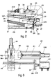
- the required support frame 17 is firstly positioned laterally and then moved lengthwise by advancement means 44 (see Fig. 2).
- an extraction hook 28 is attached to the support frame 17, which comprises a frontal latch 29.
- the operator 20 acts on a jack 27 by means of a control panel 21, extracts the support frame 17 frame the movable carriage 13 and positions such frame near to and in cooperation with the alignment and abutment assemblage 43.
- the intermediate lifter means 24 may consist of an electrical, pneumatic or hydraulic jack or of a system of levers or a pantograph system and will be able to be extended to various lengths to suit the operators requirements. It serves firstly to facilitate engagement of the single bars and then to facilitate their withdrawal from a bundle. The balancing condition imparted to the bundle enables the operator to position the bars with a minimum of effort.
- the lifter means 24 enables the bundle of bars to be positioned at the most convenient height on each occasion while the bundle is being used up.
- the support frame 17 comprises at its front end a container trough 25 in which are positioned the ends of the single bars of the bundle 115.
- the front terminal portion of such trough 25 is conformed with one side 30 inclined less then 60° to the horizontal and with a substantially vertical upward extension 31 of such side 30.
- the inclined side 30 serves to facilitate the upward withdrawal of the single bars, whereas the vertical extension 31 prevents the single bars leaving the trough 25 by sliding on the inclined side 30 during the lengthwise movement of the support frame 17.
- the operator 20 takes one or more bars at a time and positions them within an open movable gripper 35.
- the operator has only to lift the front terminal portion of one or more bars and to place it within the open movable gripper 35.
- the operator 20 will position within the open gripper 35 (Fig. 4a) as many bars as can be sheared by the shearing machine in one single stroke.
- the gripper 35 and the means which move it (Fig. 3), an abutment plate 36 and a jack 37 constitute the aligment and abutment assemblage 43.
- the plurality of bars involved in the preparation step is referenced with 22 and is positioned with the end portions not aligned Figs; 4a-4b-4c-4d).
- the movable gripper 35 (Fig. 4d) is then opened and retreats and is re-positioned (Fig. 4e), while the abutment plate 36 returns to its fully forward position 136 and aligns the ends of the bars forming the bundle 22.
- the intermediate lifter means 24 can be provided also with a vibratory movement, at least during the step of aligning the ends of the bars (Figs. 4d and 4e).
- the abutment plate 36 at least during the alignment step, can also be provided with a vibratory and/or knocking movement.
- the bundle 22 of bars with the ends aligned is then transferred onto supports 34 (Fig. 4g), being already prepared (122) and waiting for a bundle already positioned for shearing 222 to be finally sheared so that it can be replaced.
- the operator can form a new bundle 22 and repeat the alignment and abutment cycle (Fig. 4) without any idle times intervening.
- the movable gripper 35 consists of a stationary jaw and a movable jaw 38, which slides on guides 142 and is actuated by a jack 39.
- the movable gripper 35 is supported on a gripper-bearing carriage 40, which runs in guides 42 and us driven by a jack 139 by means of a shaft 41.
- the prepared bundle 122 is brought onto the shearing line, being taken and lifted by feeder means consisting, for instance, of an engagement and lifter means 33 and by a damping gripper 32, which together arrange to feed shears 19 possibly equipped with means 23 to discharge sheared bars.
- Figs. 5a and 5b show the working cycle of the engagement and lifter means 33, which comprise a main casing 45 able to move vertically from a position 45a to a position 45b and vice versa.
- the prepared bundle 122 held on the supports 35 is engaged at position 45b, whereas the bundle at 222 in Fig. 1 is fed to the shears at position 45a.
- the main casing 45 is driven by a jack 245 along vertical guides 145.
- Two sets of idler rollers are included to take the prepared bundle 122 from the supports 34.
- the lower rollers 47 are supported by a casing 46 which can be moved horizontally by an actuator 146. Such movement is necessary to enable the roller 47 to pass under the prepared bundle 122 so as to engage it (see Fig. 5b). Instead, the upper rollers 49 are fitted to the end of a casing 48 which can be moved vertically to secure the prepared bundle 122 when the latter is rested on the lower roller 47.
- This vertically movable casing 48 is driven by a jack 148.
- a movable abutment 51 is also included and is driven by a jack 151; it has the task of clamping laterally against a stationary abutment 50 on the main casing 45 the prepared bundle 122 of bars already engaged between the upper and lower rollers 49-47.
- the main casing 45 lies initially at position 45a (Fig. 5a) and is brought by the jack 245 to position 45b shown with lines of dashes in Fig. 5a.
- the horizontally movable casing 46 with the lower rollers 47 is retracted, as also is the movable abutment 51. In this way the whole casing 45 can be brought to position 45b (Fig. 5b) without coming into contact with the prepared bundle 122.
- the horizontally movable casing 46 is brought to its forward position 46A by the jack 146.
- the lower roller 47 is thus brought under the prepared bundle 122.
- the bevelled end of the roller 47 enables it to pass along the edge of the prepared bundle 122 without coming into contact with it.
- the vertically movable casing 48 is now lowered (Fig. 5c) to a position 48A for securing the prepared bundle 122, owing to the action of the jack 148.
- Position 48A will be adapted to suit the diameter of the bars forming the prepared bundle 122, for the halting of the vertically movable casing 48 is determined precisely by the abutment of the set of upper rollers 49 against the prepared bundle 122.
- the movable abutment 51 is now moved forward by the jack 151 to a forward position 51A determined by the prepared bundle 122.
- the main casing 45 is now raised again with a movement shown by an arrow in Fig. 5d.
- the prepared bundle 122 is therefore taken from the supports 34 and brought to the feeding position (222).
- the bundle in the feeding position 222 can now be fed to the shears by the clamping gripper 32 (Fig. 2).
- the movable abutment 51 may be slackened to assist the sliding of the bundle, for instance by releasing the pressure in the jack 151.
- the bundle takes up altogether four vertically arranged, successive positions, of which one 115 is a position of balancing on the support frame 17, another 22 is a position of engagement by the movable gripper 35 and abutment plate 36, another 122 is an intermediate position on the supports 34 and the last is the feeding position 222.
- the transfer of the bundle onto the supports 34 may be carried out by hand, as in the example shown, or automatically or semi-automatically; in the last two cases the supports, for instance, will return, descend, move forward below the bars and lift them in a manner analogous to that described regarding the feeder means 33.
- a variant provides for transfer arms means which displace the aligned bundle from its butting position 22 to its prepared position 122.
- the bundles 115, 122 and 222 are positioned in the neighbourhood of one single plane, which can be oriented as required but will advantageously be substantially vertical, as shown in Figs. 1 and 2, for instance.
Landscapes
- Engineering & Computer Science (AREA)
- Mechanical Engineering (AREA)
- Accessories And Tools For Shearing Machines (AREA)
- Feeding Of Articles To Conveyors (AREA)
- Pinball Game Machines (AREA)
- Branching, Merging, And Special Transfer Between Conveyors (AREA)
- Advancing Webs (AREA)
- Vending Machines For Individual Products (AREA)
- Electrical Discharge Machining, Electrochemical Machining, And Combined Machining (AREA)
- Manufacture, Treatment Of Glass Fibers (AREA)
- Attitude Control For Articles On Conveyors (AREA)
Claims (10)
Priority Applications (1)
| Application Number | Priority Date | Filing Date | Title |
|---|---|---|---|
| AT85202144T ATE57633T1 (de) | 1985-01-21 | 1985-12-27 | Vorrichtung zum zufuehren von staeben. |
Applications Claiming Priority (2)
| Application Number | Priority Date | Filing Date | Title |
|---|---|---|---|
| IT8331785 | 1985-01-21 | ||
| IT83317/85A IT1187529B (it) | 1985-01-21 | 1985-01-21 | Dispositivo di alimentazione barre |
Publications (3)
| Publication Number | Publication Date |
|---|---|
| EP0188850A2 EP0188850A2 (fr) | 1986-07-30 |
| EP0188850A3 EP0188850A3 (en) | 1987-02-04 |
| EP0188850B1 true EP0188850B1 (fr) | 1990-10-24 |
Family
ID=11320026
Family Applications (1)
| Application Number | Title | Priority Date | Filing Date |
|---|---|---|---|
| EP85202144A Expired - Lifetime EP0188850B1 (fr) | 1985-01-21 | 1985-12-27 | Dispositif pour alimenter des barres |
Country Status (7)
| Country | Link |
|---|---|
| US (1) | US4732066A (fr) |
| EP (1) | EP0188850B1 (fr) |
| JP (1) | JPS61182715A (fr) |
| AT (1) | ATE57633T1 (fr) |
| DE (1) | DE3580264D1 (fr) |
| ES (1) | ES8700115A1 (fr) |
| IT (1) | IT1187529B (fr) |
Cited By (3)
| Publication number | Priority date | Publication date | Assignee | Title |
|---|---|---|---|---|
| AT396081B (de) * | 1991-02-12 | 1993-05-25 | Industrieanlagen Planungs Und | Verfahren und vorrichtung zum handhaben langgestreckter werkstuecke, insbesondere von rohren |
| DE102019125159A1 (de) * | 2019-09-18 | 2021-03-18 | Sandvik Materials Technology Deutschland Gmbh | Transportsystem für ein Rohr, einen Draht oder ein Blech und Verfahren zum Ausliefern eines Rohrs, eines Drahts oder eines Blechs |
| RU2773074C2 (ru) * | 2017-12-22 | 2022-05-30 | М.Э.П. Маккине Элеттронике Пьегатричи C.П.А. | Устройство и способ обработки прутков |
Families Citing this family (31)
| Publication number | Priority date | Publication date | Assignee | Title |
|---|---|---|---|---|
| DE3802297C2 (de) * | 1988-01-27 | 1996-11-28 | Peddinghaus Rolf | Anschlagvorrichtung für eine Werkzeugmaschine zum Scheren, Stanzen und Klinken von Blechen und Profilstahlwerkstücken |
| SE467689B (sv) * | 1990-12-18 | 1992-08-31 | Renholmens Mek Verkstad Ab | Foerfarande och anordning foer kapning av roer, innefattande ett roterbart vridorgan med ett par diametralt motsatta haemt- och kaplaegen |
| ES2072641T3 (es) * | 1991-02-28 | 1995-07-16 | Piegatrici Macch Elettr | Planta para seleccionar y curvar barras para trabajos de construccion. |
| US5582056A (en) * | 1994-11-14 | 1996-12-10 | Itami Industrial Co., Ltd. | Installation for cutting a knife material |
| JP3408899B2 (ja) * | 1995-08-18 | 2003-05-19 | 光信 飯野 | 中空管の自動切断装置における工作物の給排装置 |
| IT1288751B1 (it) * | 1996-10-11 | 1998-09-24 | Lorenzo Peruzzo | Impianto per tagliare e sagomare barre di acciaio, particolarmente barre per l'armatura di cemento |
| US6290055B1 (en) * | 1997-09-09 | 2001-09-18 | Paul Glorfield | Device for orienting and achieving the optimal density of a quantity of elongated objects |
| JP4136127B2 (ja) * | 1998-10-30 | 2008-08-20 | 株式会社アルプスツール | 棒材取出し装置 |
| IT1310530B1 (it) * | 1999-02-04 | 2002-02-18 | Piegatrici Macch Elettr | Impianto di taglio per prodotti lunghi |
| EP1356876B1 (fr) * | 2002-04-26 | 2007-05-16 | Schnell S.p.A. | Méthode et dispositif pour l'alimentation automatique des métaux profilés en forme de barre dans des systèmes d'usinage de ces métals profilés |
| ES2241392B1 (es) * | 2002-09-23 | 2007-03-16 | Ferrallados Alameda, S.L. | Planta para manipulacion de barras de acero para armaduras, zunchos y similares. |
| ITUD20040012A1 (it) * | 2004-01-23 | 2004-04-23 | Piegatrici Macch Elettr | Dispositivo alimentatore per barre e relativo procedimento di alimentazione |
| US7234911B2 (en) * | 2004-11-30 | 2007-06-26 | Krb Machinery Co. | Method and machine for separating profiled elements |
| ITBO20050615A1 (it) * | 2005-10-14 | 2007-04-15 | Schnell Spa | Metodo e apparecchiatura per l'alimentazione automatica di profilati metallici in barre |
| TWI309185B (en) * | 2007-01-03 | 2009-05-01 | Iner Aec Executive Yuan | Tube cutting device and method thereof |
| DK177122B1 (da) * | 2007-04-23 | 2011-11-14 | Pedax As | Apparat samt fremgangsmåde til at tælle og separere stænger |
| ITUD20080049A1 (it) * | 2008-03-07 | 2009-09-08 | Piegatrici Macch Elettr | Dispositivo alimentatore per barre e relativo procedimento di alimentazione |
| ITUD20080097A1 (it) * | 2008-05-06 | 2009-11-07 | Piegatrici Macch Elettr | Apparecchiatura di alimentazione e taglio per barre metalliche, e relativo procedimento |
| JP4920727B2 (ja) * | 2009-07-17 | 2012-04-18 | 大東精機株式会社 | 長尺材搬送位置決め装置 |
| JP5468352B2 (ja) * | 2009-10-26 | 2014-04-09 | 昭和電工株式会社 | 棒状ワークの切断方法 |
| ITTO20120083A1 (it) * | 2012-02-01 | 2013-08-02 | Oscam Spa | Impianto di piegatura di barre metalliche |
| ITBO20120507A1 (it) | 2012-09-21 | 2014-03-22 | Dante Bruno Priuli | Metodo e apparecchiatura per il carico di profilati metallici in barre |
| IT201700109834A1 (it) * | 2017-10-02 | 2019-04-02 | M E P Macch Elettroniche Piegatrici Spa | Apparato e metodo di alimentazione di barre |
| AR113669A1 (es) | 2017-12-22 | 2020-05-27 | A C M S R L Automatismi Costruzioni Mecc | Aparato y método de elaboración de barras |
| AR122922A1 (es) * | 2017-12-22 | 2022-10-19 | M E P Macch Elettroniche Piegatrici Spa | Aparato y método de provisión de barras |
| IT201800010247A1 (it) * | 2018-11-12 | 2020-05-12 | M E P Macch Elettroniche Piegatrici Spa | Apparato e metodo di manipolazione di barre |
| IT201900015168A1 (it) * | 2019-08-28 | 2021-02-28 | A C M S R L Automatismi Costruzioni Mecc | Apparato e metodo per l'alimentazione di barre |
| IT202000002365A1 (it) * | 2020-02-06 | 2021-08-06 | Schnell Spa | Metodo per l’ottimizzazione del taglio e gruppo manipolatore di prodotti di foggia allungata |
| CN111493440B (zh) * | 2020-04-23 | 2021-11-30 | 安徽恒益纺织科技有限公司 | 一种口罩内衬钢丝切段装置及其使用方法 |
| IT202100014078A1 (it) | 2021-05-28 | 2022-11-28 | Schnell Spa | Gruppo caricatore per elementi oblunghi, in particolare metallici |
| IT202200021570A1 (it) * | 2022-10-19 | 2024-04-19 | Dallan Spa | Linea e metodo per la produzione e l’impacchettamento di profili metallici |
Family Cites Families (25)
| Publication number | Priority date | Publication date | Assignee | Title |
|---|---|---|---|---|
| DE20775C (de) * | A. FlGGE in London | Neuerung an Wasserrädern ] oder Schaufelrädern | ||
| US1392871A (en) * | 1919-03-12 | 1921-10-04 | Goodyear Tire & Rubber | Measuring and cutting apparatus |
| US1871077A (en) * | 1929-08-31 | 1932-08-09 | Oliver M Mowat | Apparatus for serving tube finishing machines |
| DE1114164B (de) * | 1956-10-09 | 1961-09-28 | Miehle Goss Dexter Inc | Einrichtung an Papierschneidemaschinen zur Abdeckung des fuer den Anlegeanschlag vorgesehenen Fuehrungsschlitzes |
| US3045846A (en) * | 1960-09-19 | 1962-07-24 | William B Clark | Rack unloader |
| DE1235433B (de) * | 1961-08-16 | 1967-03-02 | Fuba Werk Elektronischer Baute | Verfahren zur Herstellung von elektrischen Plattenkondensatoren oder aehnlichen elektrischen Bauelementen durch Abtrennen der Bauelemente von einem langgestreckten Vorratsprodukt |
| DE1502837B1 (de) * | 1963-05-17 | 1970-08-20 | Kurt Laevemann | Zufoerderanlage einer Zuschneide- und Biegeanlage fuer Stahlstaebe fuer Betonbauten od.dgl. |
| US3542226A (en) * | 1968-11-26 | 1970-11-24 | Pineville Kraft Corp | Wire pole handling apparatus |
| US3647092A (en) * | 1970-03-27 | 1972-03-07 | Ontario Paper Co Ltd | Log bundle aligner |
| CH557285A (de) * | 1972-11-03 | 1974-12-31 | Krapf Oswald | Transport- und zuschneideanlage fuer armierungseisen. |
| US3832928A (en) * | 1972-11-30 | 1974-09-03 | H Copeland | Portable pulpwood slashing machine |
| US3871288A (en) * | 1973-11-23 | 1975-03-18 | Automation Development Corp | Automatic bar handling system |
| DE2456086B2 (de) * | 1974-11-27 | 1976-09-16 | Peddinghaus, Carl Ulrich, Dr., 5600 Wuppertal | Foerdereinrichtung fuer betonstahlstaebe |
| FR2323184A1 (fr) * | 1975-09-05 | 1977-04-01 | Ibm | Systeme de manipulation d'echantillons |
| AT345636B (de) * | 1976-02-09 | 1978-09-25 | Best Baueisen & Stahl | Vorrichtung zum zufuehren von bewehrungsstaeben |
| DE2620406B2 (de) * | 1976-05-08 | 1980-04-03 | Gerhard 4600 Dortmund Hindrichs | Montagevorrichtung zum Einschieben der Rohre in die Rohrboden von großen Wärmetauschanlagen |
| SU650913A1 (ru) * | 1977-04-28 | 1979-03-05 | Nikolenko Dmitrij | Устройство дл выравнивани торцов бревен |
| US4182206A (en) * | 1977-07-15 | 1980-01-08 | Bundy Corporation | Cylindrical member processing apparatus |
| US4204788A (en) * | 1978-07-31 | 1980-05-27 | Massey John P | Squaring device for storage of rods, tubes, and like articles |
| AT373798B (de) * | 1981-06-25 | 1984-02-27 | Hufnagl & Co Rista Draht | Vorrichtung zur zufuehrung von abgelaengten draehten zu einer verarbeitungsmaschine |
| JPS58202213A (ja) * | 1982-05-17 | 1983-11-25 | Mitsui Eng & Shipbuild Co Ltd | 棒状体群から棒状体を一本ずつ取り出す装置 |
| IT1193053B (it) * | 1982-09-27 | 1988-06-02 | E Soc Automatismi Elettronici | Pinza di estrazione di barre metalliche da fasci |
| IT1193054B (it) * | 1982-09-27 | 1988-06-02 | E Soc Automatismi Elettronici | Metodo ed impianto di taglio di barre metalliche in spezzoni di minor lunghezza |
| JPS59194936A (ja) * | 1983-04-21 | 1984-11-05 | Narasaki Zosen Kk | 棒材移載装置 |
| FI67525C (fi) * | 1983-06-16 | 1985-04-10 | Rautaruukki Oy | Staplingsanordning foer roer o dyl laongstraeckta foeremaol i ch foer bildande av ett knippe av bestaemd form |
-
1985
- 1985-01-21 IT IT83317/85A patent/IT1187529B/it active
- 1985-12-27 DE DE8585202144T patent/DE3580264D1/de not_active Expired - Fee Related
- 1985-12-27 EP EP85202144A patent/EP0188850B1/fr not_active Expired - Lifetime
- 1985-12-27 AT AT85202144T patent/ATE57633T1/de not_active IP Right Cessation
-
1986
- 1986-01-20 ES ES551034A patent/ES8700115A1/es not_active Expired
- 1986-01-20 JP JP61009814A patent/JPS61182715A/ja active Pending
- 1986-01-21 US US06/821,057 patent/US4732066A/en not_active Expired - Fee Related
Cited By (3)
| Publication number | Priority date | Publication date | Assignee | Title |
|---|---|---|---|---|
| AT396081B (de) * | 1991-02-12 | 1993-05-25 | Industrieanlagen Planungs Und | Verfahren und vorrichtung zum handhaben langgestreckter werkstuecke, insbesondere von rohren |
| RU2773074C2 (ru) * | 2017-12-22 | 2022-05-30 | М.Э.П. Маккине Элеттронике Пьегатричи C.П.А. | Устройство и способ обработки прутков |
| DE102019125159A1 (de) * | 2019-09-18 | 2021-03-18 | Sandvik Materials Technology Deutschland Gmbh | Transportsystem für ein Rohr, einen Draht oder ein Blech und Verfahren zum Ausliefern eines Rohrs, eines Drahts oder eines Blechs |
Also Published As
| Publication number | Publication date |
|---|---|
| ATE57633T1 (de) | 1990-11-15 |
| JPS61182715A (ja) | 1986-08-15 |
| ES551034A0 (es) | 1986-10-16 |
| IT1187529B (it) | 1987-12-23 |
| DE3580264D1 (de) | 1990-11-29 |
| ES8700115A1 (es) | 1986-10-16 |
| IT8583317A0 (it) | 1985-01-21 |
| EP0188850A2 (fr) | 1986-07-30 |
| US4732066A (en) | 1988-03-22 |
| EP0188850A3 (en) | 1987-02-04 |
Similar Documents
| Publication | Publication Date | Title |
|---|---|---|
| EP0188850B1 (fr) | Dispositif pour alimenter des barres | |
| US4524656A (en) | Method for cutting metal rods into shorter lengths | |
| JPH10506330A (ja) | ロボット装置 | |
| EP0117273A1 (fr) | Appareil pour fixer automatiquement des connecteurs à des fins de câbles | |
| JPS59133919A (ja) | 工作物マニピユレ−シヨン装置 | |
| EP0501212B1 (fr) | Installation pour sélectionner et plier des barres pour la construction civile | |
| EP1706231B1 (fr) | Dispositif d'alimentation pour barres et procede d'alimentation associee | |
| CN218692657U (zh) | 一种上料、缩头、拉拔一体机 | |
| EP1980341B1 (fr) | Appareil et procédé pour charger automatiquement de barres métalliques | |
| CN116512449B (zh) | 一种硅棒头尾料切割方法 | |
| CN207344121U (zh) | 自动插管设备 | |
| JP2846210B2 (ja) | フィンコイル自動供給装置 | |
| CN210619500U (zh) | 一种多工位的金属丝分料上料设备 | |
| CN209793114U (zh) | 液压支架导向套全自动生产线 | |
| NO810246L (no) | Anordning for fjerning av traader eller baand fra f.eks. forpakninger. | |
| GB1131192A (en) | Apparatus for withdrawing suspension rods from cathode plates | |
| CN116533402B (zh) | 一种晶圆棒开方控制系统及控制方法 | |
| CN218664299U (zh) | 一种周转料盒的自动堆叠料机 | |
| CN218611965U (zh) | 一种自动上料的钢材切断机 | |
| CN113865451A (zh) | 一种电子雷管导线线把快速转模工艺及装备 | |
| SU941033A1 (ru) | Механизированный комплекс дл раскро листового проката | |
| JPH08175666A (ja) | 万棒分配方法および装置 | |
| JPH02264062A (ja) | チーズ,スペーサ等の装填,抜取り方法及びこれらの方法に用いる装置 | |
| JPH09254127A (ja) | 鉄筋マット自動組付システム | |
| CN120055823A (zh) | 一种拱形支架自动化作业生产线 |
Legal Events
| Date | Code | Title | Description |
|---|---|---|---|
| PUAI | Public reference made under article 153(3) epc to a published international application that has entered the european phase |
Free format text: ORIGINAL CODE: 0009012 |
|
| AK | Designated contracting states |
Kind code of ref document: A2 Designated state(s): AT BE CH DE FR GB LI LU NL SE |
|
| PUAL | Search report despatched |
Free format text: ORIGINAL CODE: 0009013 |
|
| AK | Designated contracting states |
Kind code of ref document: A3 Designated state(s): AT BE CH DE FR GB LI LU NL SE |
|
| RHK1 | Main classification (correction) |
Ipc: B21D 43/28 |
|
| 17P | Request for examination filed |
Effective date: 19870610 |
|
| 17Q | First examination report despatched |
Effective date: 19880822 |
|
| GRAA | (expected) grant |
Free format text: ORIGINAL CODE: 0009210 |
|
| AK | Designated contracting states |
Kind code of ref document: B1 Designated state(s): AT BE CH DE FR GB LI LU NL SE |
|
| PG25 | Lapsed in a contracting state [announced via postgrant information from national office to epo] |
Ref country code: SE Effective date: 19901024 Ref country code: NL Effective date: 19901024 Ref country code: BE Effective date: 19901024 Ref country code: AT Effective date: 19901024 |
|
| REF | Corresponds to: |
Ref document number: 57633 Country of ref document: AT Date of ref document: 19901115 Kind code of ref document: T |
|
| REF | Corresponds to: |
Ref document number: 3580264 Country of ref document: DE Date of ref document: 19901129 |
|
| ET | Fr: translation filed | ||
| PG25 | Lapsed in a contracting state [announced via postgrant information from national office to epo] |
Ref country code: LU Free format text: LAPSE BECAUSE OF NON-PAYMENT OF DUE FEES Effective date: 19901231 |
|
| NLV1 | Nl: lapsed or annulled due to failure to fulfill the requirements of art. 29p and 29m of the patents act | ||
| PLBE | No opposition filed within time limit |
Free format text: ORIGINAL CODE: 0009261 |
|
| STAA | Information on the status of an ep patent application or granted ep patent |
Free format text: STATUS: NO OPPOSITION FILED WITHIN TIME LIMIT |
|
| 26N | No opposition filed | ||
| REG | Reference to a national code |
Ref country code: CH Ref legal event code: PUE Owner name: IMPIANTI INDUSTRIALI S.P.A. |
|
| REG | Reference to a national code |
Ref country code: FR Ref legal event code: CL |
|
| REG | Reference to a national code |
Ref country code: GB Ref legal event code: 732 |
|
| PGFP | Annual fee paid to national office [announced via postgrant information from national office to epo] |
Ref country code: GB Payment date: 19921221 Year of fee payment: 8 |
|
| PGFP | Annual fee paid to national office [announced via postgrant information from national office to epo] |
Ref country code: CH Payment date: 19921229 Year of fee payment: 8 |
|
| PGFP | Annual fee paid to national office [announced via postgrant information from national office to epo] |
Ref country code: FR Payment date: 19921231 Year of fee payment: 8 |
|
| PGFP | Annual fee paid to national office [announced via postgrant information from national office to epo] |
Ref country code: DE Payment date: 19930122 Year of fee payment: 8 |
|
| PG25 | Lapsed in a contracting state [announced via postgrant information from national office to epo] |
Ref country code: GB Effective date: 19931227 |
|
| PG25 | Lapsed in a contracting state [announced via postgrant information from national office to epo] |
Ref country code: LI Effective date: 19931231 Ref country code: CH Effective date: 19931231 |
|
| GBPC | Gb: european patent ceased through non-payment of renewal fee |
Effective date: 19931227 |
|
| PG25 | Lapsed in a contracting state [announced via postgrant information from national office to epo] |
Ref country code: FR Effective date: 19940831 |
|
| REG | Reference to a national code |
Ref country code: CH Ref legal event code: PL |
|
| PG25 | Lapsed in a contracting state [announced via postgrant information from national office to epo] |
Ref country code: DE Effective date: 19940901 |
|
| REG | Reference to a national code |
Ref country code: FR Ref legal event code: ST |