EP0189020A1 - Plaque de montage pour chauffage par le sol - Google Patents
Plaque de montage pour chauffage par le sol Download PDFInfo
- Publication number
- EP0189020A1 EP0189020A1 EP85890254A EP85890254A EP0189020A1 EP 0189020 A1 EP0189020 A1 EP 0189020A1 EP 85890254 A EP85890254 A EP 85890254A EP 85890254 A EP85890254 A EP 85890254A EP 0189020 A1 EP0189020 A1 EP 0189020A1
- Authority
- EP
- European Patent Office
- Prior art keywords
- projections
- mounting plate
- film
- plate
- pipes
- Prior art date
- Legal status (The legal status is an assumption and is not a legal conclusion. Google has not performed a legal analysis and makes no representation as to the accuracy of the status listed.)
- Granted
Links
- 238000010438 heat treatment Methods 0.000 title claims abstract description 15
- 239000004033 plastic Substances 0.000 claims abstract description 5
- 229920003023 plastic Polymers 0.000 claims abstract description 5
- 229920006327 polystyrene foam Polymers 0.000 claims abstract description 4
- 239000002985 plastic film Substances 0.000 claims description 10
- 229920006255 plastic film Polymers 0.000 claims description 10
- 239000004793 Polystyrene Substances 0.000 claims description 4
- 239000002984 plastic foam Substances 0.000 claims description 4
- 229920002223 polystyrene Polymers 0.000 claims description 3
- 239000006260 foam Substances 0.000 abstract description 3
- 238000004519 manufacturing process Methods 0.000 description 4
- 239000000463 material Substances 0.000 description 3
- 150000001875 compounds Chemical class 0.000 description 2
- 239000000155 melt Substances 0.000 description 2
- 229910000831 Steel Inorganic materials 0.000 description 1
- 230000000694 effects Effects 0.000 description 1
- 230000002349 favourable effect Effects 0.000 description 1
- 239000006261 foam material Substances 0.000 description 1
- 238000009413 insulation Methods 0.000 description 1
- 239000007788 liquid Substances 0.000 description 1
- 239000010959 steel Substances 0.000 description 1
- XLYOFNOQVPJJNP-UHFFFAOYSA-N water Substances O XLYOFNOQVPJJNP-UHFFFAOYSA-N 0.000 description 1
Images


Classifications
-
- F—MECHANICAL ENGINEERING; LIGHTING; HEATING; WEAPONS; BLASTING
- F24—HEATING; RANGES; VENTILATING
- F24D—DOMESTIC- OR SPACE-HEATING SYSTEMS, e.g. CENTRAL HEATING SYSTEMS; DOMESTIC HOT-WATER SUPPLY SYSTEMS; ELEMENTS OR COMPONENTS THEREFOR
- F24D3/00—Hot-water central heating systems
- F24D3/12—Tube and panel arrangements for ceiling, wall, or underfloor heating
- F24D3/14—Tube and panel arrangements for ceiling, wall, or underfloor heating incorporated in a ceiling, wall or floor
- F24D3/141—Tube mountings specially adapted therefor
- F24D3/142—Tube mountings specially adapted therefor integrated in prefab construction elements
-
- Y—GENERAL TAGGING OF NEW TECHNOLOGICAL DEVELOPMENTS; GENERAL TAGGING OF CROSS-SECTIONAL TECHNOLOGIES SPANNING OVER SEVERAL SECTIONS OF THE IPC; TECHNICAL SUBJECTS COVERED BY FORMER USPC CROSS-REFERENCE ART COLLECTIONS [XRACs] AND DIGESTS
- Y02—TECHNOLOGIES OR APPLICATIONS FOR MITIGATION OR ADAPTATION AGAINST CLIMATE CHANGE
- Y02B—CLIMATE CHANGE MITIGATION TECHNOLOGIES RELATED TO BUILDINGS, e.g. HOUSING, HOUSE APPLIANCES OR RELATED END-USER APPLICATIONS
- Y02B30/00—Energy efficient heating, ventilation or air conditioning [HVAC]
Definitions
- the invention relates to a mounting plate for the pipes of floor heating systems with projections projecting upwards on the top, between which the heating pipes can be clamped, the mounting plate and its projections preferably being made in one piece from plastic foam, in particular polystyrene foam.
- mounting plates of the type mentioned at the beginning.
- Such a plate is known for example from AT-PS 361 185.
- the disadvantage of these known mounting plates is that they do not have the strength required for a secure hold of the pipes and, moreover, easily break off the projections when the underfloor heating pipes are laid.
- the known mounting plates have the disadvantage that they are more or less permeable to water, so that the wet setting of the screed compound required for strength reasons is not guaranteed.
- the invention has for its object to provide a mounting plate of the type mentioned that is easy to manufacture and meets all requirements for a mounting plate for underfloor heating pipes.
- the mounting plate according to the invention consists of plastic foam, which is covered with a plastic film, on the one hand the favorable properties (insulation) and the ease of manufacture of mounting plates made of plastic foam are maintained, but by the arrangement of the plastic film, the plate and in particular those provided on it Mounting projections are extremely firm. In the same way it is achieved that this clamping force necessary for the secure hold of the pipes of the underfloor heating is readily applied by the projections of the mounting plate.
- the film is a thermally deformable film which, when heated, i.e. plastically deformable state is applied to the top of the mounting plate and the projections.
- This measure has the advantage that the plastic film lies particularly close to the surfaces of the mounting plate to be covered, without the need for particularly complex manufacturing measures.
- the film is fused to the surfaces of the mounting plate and the projections. This measure further increases the strength of the mounting plate, including the projections provided on it.
- the mounting plate including the projections and the film consist of the same plastic, in particular of polystyrene.
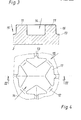
- the mounting plate 1 shown in FIGS. 1 and 2 consists of a plate 2 which has longitudinal ribs 3 and 4 projecting on two of its edges, these ribs lying in the region of the top side 5 of the plate 2.
- longitudinal ribs 6 and 7 are also provided, but which are in the area of the underside of the plate 2, so that there is a stepped fold-like joint between adjacent mounting plates 1.
- dovetail-widening cams 8 are provided on the top of the longitudinal ribs 6 and 7, which engage in correspondingly shaped, undercut recesses 9 in the longitudinal ribs 3 and 4 when mounting plates 1 are arranged next to one another.
- projections 11 are provided which are uniformly distributed over the mounting plate and are combined in the embodiment shown to form groups of four, only a few of which are shown in FIG.
- Recesses 12 are provided between each two adjacent protrusions 11, into which tubes of an underfloor heating system can be clamped.
- the projections 11 are stiffened by the arrangement of support ribs 13.
- the projections 11 are formed in one piece with the plate 2, although this is not mandatory, since the projections 11 are also attached to a plate 2, e.g. can be glued, welded, etc.
- FIG. 3 also shows, the projections 11 and the regions 14 and 15 of the upper side 5 of the mounting plate 1 arranged between the projections are covered with a film 16 made of plastic.
- the film 16 lies tightly against the surfaces of the plate 2 and the projections 11.
- Flat projections 17 can be arranged on the underside of the mounting plate, which can have, for example, a square outline shape.
- the mounting plate according to the invention there is the possibility of producing the mounting plate according to the invention in that 16 plastic is introduced and foamed into a correspondingly preformed plastic film.
- Another option is to produce the plate 2 with the projections 11 from synthetic foam in a conventional form and to cover the finished plate with a thermally deformable plastic film 16, for example a film made of polystyrene. Characterized in that the film is applied to the top of the mounting plate and the projections in the heated state, the film melts with the material of the mounting plate, so that there is a particularly good stiffening of the mounting plate according to the invention, in particular also in the region of the projections 11.
- the film 16 can extend into the region of the side edges of the plate 2 and the ribs 3 and 4 or 6 and 7 provided there or the grooves 20, 21 or 23, 24.
- the film 16 By applying the film 16 in the heated state, it is particularly easy to achieve that the film 16 melts on the surface with the foam material of the plate 2 and the protrusions 11, which results in a particularly intimate connection between the film and the material of the plate 2 and that of the protrusions 11 results.
- the mounting plate according to the invention there is a particularly good holding of pipes for underfloor heating, since the projections 11 which clamp the pipes are reinforced by the arrangement of the plastic film, in particular when this is applied in the heated state and fused to the plate material, so that the projections are good Can apply clamping effect.
- the mounting plate according to the invention is practically impermeable to liquids, so that a wet setting of a screed compound applied after laying the mounting plates 1 and the underfloor heating pipes is ensured.
- FIGS. 5 and 6 are connected to one another via hook fold like connecting elements connectable.
- Grooves 20, 21 which are open at the bottom and meet at two edges meeting at a corner are closed at their ends by transverse walls 22.
- Grooves 23, 24 which are open at the top are provided on the other two edges.
- the walls 25, 26 delimiting the grooves end at a distance from the corner 27 of the mounting plate, so that space is created for the engagement of the transverse walls 22 when the mounting plates are joined together.
- the film 16 extends beyond the edge configurations of the mounting plates (edges, 3, 4, 5, 6 or grooves 21 to 24).
Landscapes
- Engineering & Computer Science (AREA)
- Physics & Mathematics (AREA)
- Thermal Sciences (AREA)
- Chemical & Material Sciences (AREA)
- Combustion & Propulsion (AREA)
- Mechanical Engineering (AREA)
- General Engineering & Computer Science (AREA)
- Steam Or Hot-Water Central Heating Systems (AREA)
- Domestic Hot-Water Supply Systems And Details Of Heating Systems (AREA)
- Central Heating Systems (AREA)
- Floor Finish (AREA)
Applications Claiming Priority (3)
| Application Number | Priority Date | Filing Date | Title |
|---|---|---|---|
| AT233284 | 1984-07-18 | ||
| DE8429708U | 1984-10-09 | ||
| DE19848429708U DE8429708U1 (de) | 1984-07-18 | 1984-10-09 | Montageplatte fuer fussbodenheizungen |
Publications (2)
| Publication Number | Publication Date |
|---|---|
| EP0189020A1 true EP0189020A1 (fr) | 1986-07-30 |
| EP0189020B1 EP0189020B1 (fr) | 1988-06-22 |
Family
ID=3532387
Family Applications (1)
| Application Number | Title | Priority Date | Filing Date |
|---|---|---|---|
| EP85890254A Expired EP0189020B1 (fr) | 1984-07-18 | 1985-10-09 | Plaque de montage pour chauffage par le sol |
Country Status (3)
| Country | Link |
|---|---|
| EP (1) | EP0189020B1 (fr) |
| AT (1) | ATE35311T1 (fr) |
| DE (2) | DE8429708U1 (fr) |
Cited By (15)
| Publication number | Priority date | Publication date | Assignee | Title |
|---|---|---|---|---|
| EP0195903B1 (fr) * | 1985-03-19 | 1990-07-25 | Itrag AG | Elément de chauffage sous forme d'une plaque, notamment pour le chauffage du sol |
| EP0553473A1 (fr) * | 1991-12-20 | 1993-08-04 | Hewing GmbH | Système de fixation et d'écartement |
| EP0806614A1 (fr) | 1996-05-10 | 1997-11-12 | Isobouw Systems B.V. | Plaque pour fixer des tuyaux de chauffage par le sol |
| US20110047907A1 (en) * | 2009-08-28 | 2011-03-03 | DZT Industries, LLC | Method and apparatus for positioning heating elements |
| US9625163B2 (en) | 2014-08-18 | 2017-04-18 | Progress Profiles Spa | Method and apparatus for positioning heating elements |
| US9719265B2 (en) | 2015-03-17 | 2017-08-01 | Progress Profiles Spa | Floor underlayment for positioning heating elements |
| US9726383B1 (en) * | 2016-06-17 | 2017-08-08 | Progress Profiles S.P.A. | Support for radiant covering and floor heating elements |
| WO2018091346A1 (fr) * | 2016-11-17 | 2018-05-24 | Schlueter Werner | Système servant à l'installation d'un chauffage de surface |
| US10215423B2 (en) | 2014-08-18 | 2019-02-26 | Progress Profiles S.P.A. | Method and apparatus for positioning heating elements |
| US10859274B2 (en) | 2016-04-01 | 2020-12-08 | Progress Profiles S.P.A. | Support for radiant covering and floor heating elements |
| USD971449S1 (en) | 2016-04-13 | 2022-11-29 | Progress Profiles S.P.A. | Floor underlayment |
| USD1036242S1 (en) | 2020-04-22 | 2024-07-23 | Progress Profiles S.P.A. | Floor underlayment |
| USD1036243S1 (en) | 2020-10-09 | 2024-07-23 | Progress Profiles S.P.A. | Floor underlayment |
| USD1036979S1 (en) | 2020-04-06 | 2024-07-30 | Progress Profiles S.P.A. | Floor underlayment |
| USD1101979S1 (en) | 2023-02-07 | 2025-11-11 | Progress Profiles S.P.A. | Floor underlayment |
Families Citing this family (9)
| Publication number | Priority date | Publication date | Assignee | Title |
|---|---|---|---|---|
| DE3837562C2 (de) * | 1988-11-04 | 1997-11-20 | Eht Siegmund Gmbh | Flächenelement für einen beheizbaren Hohlraumboden |
| US6786992B2 (en) | 2002-06-11 | 2004-09-07 | Airdex International, Inc. | Method of making a dunnage platform |
| USD541396S1 (en) | 2005-10-21 | 2007-04-24 | Createc Corporation | Radiant heat floor panel |
| US7963397B2 (en) | 2006-02-09 | 2011-06-21 | Seagle Vance L | Modular, knock-down, light weight, thermally insulating, tamper proof shipping container and fire retardant shipping container bag |
| US7689481B2 (en) | 2006-02-15 | 2010-03-30 | Airdex International, Inc. | Light weight, strong, fire retardant dunnage platform bag and system of loading, dispensing and using bag |
| USD587358S1 (en) | 2007-09-07 | 2009-02-24 | Createc Corporation | Radiant floor panel |
| USD813421S1 (en) | 2009-08-28 | 2018-03-20 | Progress Profiles Spa | Floor underlayment |
| DE102013004325A1 (de) | 2012-06-05 | 2013-12-05 | Jackon Insulation Gmbh | Systemelement für Fußbodenheizung |
| CN105197344A (zh) | 2014-06-25 | 2015-12-30 | 艾尔戴克斯国际公司 | 承载结构 |
Citations (2)
| Publication number | Priority date | Publication date | Assignee | Title |
|---|---|---|---|---|
| DE2840148A1 (de) * | 1978-09-15 | 1980-03-27 | Siegmund Helmut Dieter Ing Gra | Verbundplatte fuer fussbodenheizungen |
| AT361185B (de) * | 1978-06-06 | 1981-02-25 | Feist Artus | Fussboden |
Family Cites Families (5)
| Publication number | Priority date | Publication date | Assignee | Title |
|---|---|---|---|---|
| DE2840149A1 (de) * | 1978-09-15 | 1980-03-27 | Siegmund Helmut Dieter Ing Gra | Verbundplatte fuer fussbodenheizungen |
| DE7902301U1 (de) * | 1979-01-29 | 1979-06-28 | Neupa Industrieerzeugnisse-Kunststoffbedarf Gmbh, 3000 Hannover | Waermedaemmende platte fuer boden- oder wandheizanlagen |
| DE2911982A1 (de) * | 1979-03-27 | 1980-10-16 | Roth Werke Gmbh | Bausatz fuer fussbodenheizungen |
| DE2929350A1 (de) * | 1979-07-20 | 1981-02-12 | Ulrich Dipl Ing Fiergolla | Verbundtraeger fuer gebaeudedecken |
| DE3024208C2 (de) * | 1980-06-27 | 1983-04-21 | Fränkische Rohrwerke Gebrüder Kirchner GmbH & Co, 8729 Königsberg | Verlegeplatte - insbesondere aus Kunststoff - mit Noppen, die ein Heiz- oder Kühlmedium führende Rohrleitungen zwischen sich halten |
-
1984
- 1984-10-09 DE DE19848429708U patent/DE8429708U1/de not_active Expired
-
1985
- 1985-10-09 AT AT85890254T patent/ATE35311T1/de not_active IP Right Cessation
- 1985-10-09 DE DE8585890254T patent/DE3563476D1/de not_active Expired
- 1985-10-09 EP EP85890254A patent/EP0189020B1/fr not_active Expired
Patent Citations (2)
| Publication number | Priority date | Publication date | Assignee | Title |
|---|---|---|---|---|
| AT361185B (de) * | 1978-06-06 | 1981-02-25 | Feist Artus | Fussboden |
| DE2840148A1 (de) * | 1978-09-15 | 1980-03-27 | Siegmund Helmut Dieter Ing Gra | Verbundplatte fuer fussbodenheizungen |
Cited By (35)
| Publication number | Priority date | Publication date | Assignee | Title |
|---|---|---|---|---|
| EP0195903B1 (fr) * | 1985-03-19 | 1990-07-25 | Itrag AG | Elément de chauffage sous forme d'une plaque, notamment pour le chauffage du sol |
| EP0553473A1 (fr) * | 1991-12-20 | 1993-08-04 | Hewing GmbH | Système de fixation et d'écartement |
| EP0806614A1 (fr) | 1996-05-10 | 1997-11-12 | Isobouw Systems B.V. | Plaque pour fixer des tuyaux de chauffage par le sol |
| NL1003082C2 (nl) * | 1996-05-10 | 1997-11-18 | Isobouw Systems Bv | Plaat geschikt voor montage van een vloerverwarmingsleiding. |
| US10006644B2 (en) | 2009-08-28 | 2018-06-26 | Progress Profiles Spa | Method and apparatus for positioning heating elements |
| US20110047907A1 (en) * | 2009-08-28 | 2011-03-03 | DZT Industries, LLC | Method and apparatus for positioning heating elements |
| US9188348B2 (en) * | 2009-08-28 | 2015-11-17 | Progress Profiles Spa | Method and apparatus for positioning heating elements |
| US20160033144A1 (en) * | 2009-08-28 | 2016-02-04 | Progress Profiles Spa | Method and apparatus for positioning heating elements |
| US9416979B2 (en) | 2009-08-28 | 2016-08-16 | Progress Profiles Spa | Method and apparatus for positioning heating elements |
| US9518746B2 (en) | 2009-08-28 | 2016-12-13 | Progress Profiles Spa | Method and apparatus for positioning heating elements |
| US11041638B2 (en) | 2009-08-28 | 2021-06-22 | Progress Profiles Spa | Method and apparatus for positioning heating elements |
| US10215423B2 (en) | 2014-08-18 | 2019-02-26 | Progress Profiles S.P.A. | Method and apparatus for positioning heating elements |
| US10712020B2 (en) | 2014-08-18 | 2020-07-14 | Progress Profiles Spa | Method and apparatus for positioning heating elements |
| US12044417B2 (en) | 2014-08-18 | 2024-07-23 | Progress Profiles Spa | Method and apparatus for positioning heating elements |
| US10107505B2 (en) | 2014-08-18 | 2018-10-23 | Progress Profiles Spa | Method and apparatus for positioning heating elements |
| US9777931B2 (en) | 2014-08-18 | 2017-10-03 | Progress Profiles Spa | Method and apparatus for positioning heating elements |
| EP3183505B1 (fr) | 2014-08-18 | 2019-04-10 | Progress Profiles SPA | Sous-couche pour le positionnement d'éléments chauffants et assemblage de sol |
| US10408469B2 (en) | 2014-08-18 | 2019-09-10 | Progress Profiles Spa | Method and apparatus for positioning heating elements |
| US9625163B2 (en) | 2014-08-18 | 2017-04-18 | Progress Profiles Spa | Method and apparatus for positioning heating elements |
| US10739016B2 (en) | 2014-08-18 | 2020-08-11 | Progress Profiles Spa | Method and apparatus for positioning heating elements |
| US9719265B2 (en) | 2015-03-17 | 2017-08-01 | Progress Profiles Spa | Floor underlayment for positioning heating elements |
| US12560339B2 (en) | 2016-04-01 | 2026-02-24 | Progress Profiles S.P.A. | Support for radiant covering and floor heating elements |
| US10502434B2 (en) | 2016-04-01 | 2019-12-10 | Progress Profiles S.P.A. | Support for radiant covering and floor heating elements |
| US10859274B2 (en) | 2016-04-01 | 2020-12-08 | Progress Profiles S.P.A. | Support for radiant covering and floor heating elements |
| USD841837S1 (en) | 2016-04-13 | 2019-02-26 | Progress Profiles S.P.A. | Floor underlayment |
| USD880732S1 (en) | 2016-04-13 | 2020-04-07 | Progress Profiles S.P.A. | Floor underlayment |
| USD874028S1 (en) | 2016-04-13 | 2020-01-28 | Progress Profiles S.P.A. | Floor underlayment |
| USD872901S1 (en) | 2016-04-13 | 2020-01-14 | Progress Profiles S.P.A. | Floor underlayment |
| USD971449S1 (en) | 2016-04-13 | 2022-11-29 | Progress Profiles S.P.A. | Floor underlayment |
| US9726383B1 (en) * | 2016-06-17 | 2017-08-08 | Progress Profiles S.P.A. | Support for radiant covering and floor heating elements |
| WO2018091346A1 (fr) * | 2016-11-17 | 2018-05-24 | Schlueter Werner | Système servant à l'installation d'un chauffage de surface |
| USD1036979S1 (en) | 2020-04-06 | 2024-07-30 | Progress Profiles S.P.A. | Floor underlayment |
| USD1036242S1 (en) | 2020-04-22 | 2024-07-23 | Progress Profiles S.P.A. | Floor underlayment |
| USD1036243S1 (en) | 2020-10-09 | 2024-07-23 | Progress Profiles S.P.A. | Floor underlayment |
| USD1101979S1 (en) | 2023-02-07 | 2025-11-11 | Progress Profiles S.P.A. | Floor underlayment |
Also Published As
| Publication number | Publication date |
|---|---|
| DE8429708U1 (de) | 1985-02-07 |
| ATE35311T1 (de) | 1988-07-15 |
| DE3563476D1 (en) | 1988-07-28 |
| EP0189020B1 (fr) | 1988-06-22 |
Similar Documents
| Publication | Publication Date | Title |
|---|---|---|
| EP0189020B1 (fr) | Plaque de montage pour chauffage par le sol | |
| DE3420473A1 (de) | Traggitter fuer abgehaengte decken | |
| DE29609497U1 (de) | Verlegesystem für Fußbodenheizungsrohre | |
| DE3815140C2 (de) | Blendrahmen zur Bildung einer Fugenschalung zwecks Verbindung von einzelnen Glasbauelementen | |
| DE9320652U1 (de) | Rahmenelement und Einsatzelement für Ställe | |
| DE2201232C3 (de) | Verfahren zum Herstellen eines kastenartigen Gehäuses | |
| DE4222971C2 (de) | Paneel zur Abdeckung bzw. Verkleidung | |
| DE3223049C2 (de) | Teppichbeschlag | |
| DE1958879A1 (de) | Plattenfoermiger Koerper aus Kunststoff | |
| EP2327846A2 (fr) | Plaque de fond en matière synthétique | |
| EP0358930A1 (fr) | Panneau de construction léger composé de modules plats | |
| DE3241424C2 (de) | Verbindungseinrichtung | |
| DE3837564C2 (de) | Hohlraumboden | |
| DE3333780A1 (de) | Waermedaemmendes fliessenverlegesystem | |
| DE19640128A1 (de) | Bodenbelag-Element | |
| EP0023711A1 (fr) | Elément de meuble | |
| DE1509448C3 (de) | Fertigbauteil | |
| DE19904982C2 (de) | Plattenförmiges Wandelement sowie Wandkonstruktion hiermit | |
| AT384873B (de) | Montageplatte fuer fussbodenheizungen | |
| DE19800375C1 (de) | Anordnung zur Lagefixierung von zu einem Bodenbelag fügbaren Paneelen | |
| DE7907136U1 (de) | Isolierplatten-Verband | |
| DE8500712U1 (de) | Abdeckplatte zum Abdecken des Bodens im Bereich von aus dem Boden herausragenden Halterungen, Pfählen u.a. | |
| DE10124756A1 (de) | Verbindungssystem und Wandsystem | |
| DE1784530A1 (de) | Zur Verwendung im Verband mit weiteren gleichartigen Bauelementen dienende Bauelemente fuer die Errichtung von Waenden,Decken,Daechern od.dgl. | |
| AT371519B (de) | Wand- und deckenkonstruktion |
Legal Events
| Date | Code | Title | Description |
|---|---|---|---|
| PUAI | Public reference made under article 153(3) epc to a published international application that has entered the european phase |
Free format text: ORIGINAL CODE: 0009012 |
|
| AK | Designated contracting states |
Kind code of ref document: A1 Designated state(s): AT BE CH DE FR GB IT LI LU NL SE |
|
| 17P | Request for examination filed |
Effective date: 19860816 |
|
| 17Q | First examination report despatched |
Effective date: 19870213 |
|
| GRAA | (expected) grant |
Free format text: ORIGINAL CODE: 0009210 |
|
| ITF | It: translation for a ep patent filed | ||
| AK | Designated contracting states |
Kind code of ref document: B1 Designated state(s): AT BE CH DE FR GB IT LI LU NL SE |
|
| REF | Corresponds to: |
Ref document number: 35311 Country of ref document: AT Date of ref document: 19880715 Kind code of ref document: T |
|
| REF | Corresponds to: |
Ref document number: 3563476 Country of ref document: DE Date of ref document: 19880728 |
|
| ET | Fr: translation filed | ||
| GBT | Gb: translation of ep patent filed (gb section 77(6)(a)/1977) | ||
| PLBE | No opposition filed within time limit |
Free format text: ORIGINAL CODE: 0009261 |
|
| STAA | Information on the status of an ep patent application or granted ep patent |
Free format text: STATUS: NO OPPOSITION FILED WITHIN TIME LIMIT |
|
| 26N | No opposition filed | ||
| ITTA | It: last paid annual fee | ||
| EPTA | Lu: last paid annual fee | ||
| EAL | Se: european patent in force in sweden |
Ref document number: 85890254.7 |
|
| PGFP | Annual fee paid to national office [announced via postgrant information from national office to epo] |
Ref country code: FR Payment date: 19951030 Year of fee payment: 11 Ref country code: AT Payment date: 19951030 Year of fee payment: 11 |
|
| PGFP | Annual fee paid to national office [announced via postgrant information from national office to epo] |
Ref country code: NL Payment date: 19951031 Year of fee payment: 11 |
|
| PGFP | Annual fee paid to national office [announced via postgrant information from national office to epo] |
Ref country code: CH Payment date: 19960104 Year of fee payment: 11 |
|
| PGFP | Annual fee paid to national office [announced via postgrant information from national office to epo] |
Ref country code: LU Payment date: 19961001 Year of fee payment: 12 |
|
| PGFP | Annual fee paid to national office [announced via postgrant information from national office to epo] |
Ref country code: SE Payment date: 19961003 Year of fee payment: 12 |
|
| PGFP | Annual fee paid to national office [announced via postgrant information from national office to epo] |
Ref country code: GB Payment date: 19961004 Year of fee payment: 12 Ref country code: DE Payment date: 19961004 Year of fee payment: 12 |
|
| PG25 | Lapsed in a contracting state [announced via postgrant information from national office to epo] |
Ref country code: AT Effective date: 19961009 |
|
| PG25 | Lapsed in a contracting state [announced via postgrant information from national office to epo] |
Ref country code: LI Effective date: 19961031 Ref country code: CH Effective date: 19961031 |
|
| PGFP | Annual fee paid to national office [announced via postgrant information from national office to epo] |
Ref country code: BE Payment date: 19961104 Year of fee payment: 12 |
|
| PG25 | Lapsed in a contracting state [announced via postgrant information from national office to epo] |
Ref country code: NL Effective date: 19970501 |
|
| REG | Reference to a national code |
Ref country code: CH Ref legal event code: PL |
|
| PG25 | Lapsed in a contracting state [announced via postgrant information from national office to epo] |
Ref country code: FR Effective date: 19970630 |
|
| NLV4 | Nl: lapsed or anulled due to non-payment of the annual fee |
Effective date: 19970501 |
|
| REG | Reference to a national code |
Ref country code: FR Ref legal event code: ST |
|
| PG25 | Lapsed in a contracting state [announced via postgrant information from national office to epo] |
Ref country code: LU Free format text: LAPSE BECAUSE OF NON-PAYMENT OF DUE FEES Effective date: 19971009 Ref country code: GB Free format text: LAPSE BECAUSE OF NON-PAYMENT OF DUE FEES Effective date: 19971009 |
|
| PG25 | Lapsed in a contracting state [announced via postgrant information from national office to epo] |
Ref country code: SE Free format text: LAPSE BECAUSE OF NON-PAYMENT OF DUE FEES Effective date: 19971010 |
|
| PG25 | Lapsed in a contracting state [announced via postgrant information from national office to epo] |
Ref country code: BE Free format text: LAPSE BECAUSE OF NON-PAYMENT OF DUE FEES Effective date: 19971031 |
|
| BERE | Be: lapsed |
Owner name: KURT HIRSCH KUNSTSTOFFWERK G.M.B.H. Effective date: 19971031 |
|
| GBPC | Gb: european patent ceased through non-payment of renewal fee |
Effective date: 19971009 |
|
| PG25 | Lapsed in a contracting state [announced via postgrant information from national office to epo] |
Ref country code: DE Free format text: LAPSE BECAUSE OF NON-PAYMENT OF DUE FEES Effective date: 19980701 |
|
| EUG | Se: european patent has lapsed |
Ref document number: 85890254.7 |