EP0189611B1 - Procédé pour la séparation chromatographique de macromolécules biologiques - Google Patents
Procédé pour la séparation chromatographique de macromolécules biologiques Download PDFInfo
- Publication number
- EP0189611B1 EP0189611B1 EP85202068A EP85202068A EP0189611B1 EP 0189611 B1 EP0189611 B1 EP 0189611B1 EP 85202068 A EP85202068 A EP 85202068A EP 85202068 A EP85202068 A EP 85202068A EP 0189611 B1 EP0189611 B1 EP 0189611B1
- Authority
- EP
- European Patent Office
- Prior art keywords
- resin
- column
- stage
- solution
- bed
- Prior art date
- Legal status (The legal status is an assumption and is not a legal conclusion. Google has not performed a legal analysis and makes no representation as to the accuracy of the status listed.)
- Expired
Links
- 0 C*(C)(*)Cc1ccccc1 Chemical compound C*(C)(*)Cc1ccccc1 0.000 description 1
Images


Classifications
-
- B—PERFORMING OPERATIONS; TRANSPORTING
- B01—PHYSICAL OR CHEMICAL PROCESSES OR APPARATUS IN GENERAL
- B01D—SEPARATION
- B01D15/00—Separating processes involving the treatment of liquids with solid sorbents; Apparatus therefor
- B01D15/08—Selective adsorption, e.g. chromatography
- B01D15/10—Selective adsorption, e.g. chromatography characterised by constructional or operational features
- B01D15/18—Selective adsorption, e.g. chromatography characterised by constructional or operational features relating to flow patterns
- B01D15/1807—Selective adsorption, e.g. chromatography characterised by constructional or operational features relating to flow patterns using counter-currents, e.g. fluidised beds
-
- A—HUMAN NECESSITIES
- A23—FOODS OR FOODSTUFFS; TREATMENT THEREOF, NOT COVERED BY OTHER CLASSES
- A23C—DAIRY PRODUCTS, e.g. MILK, BUTTER OR CHEESE; MILK OR CHEESE SUBSTITUTES; PREPARATION THEREOF
- A23C9/00—Milk preparations; Milk powder or milk powder preparations
- A23C9/14—Milk preparations; Milk powder or milk powder preparations in which the chemical composition of the milk is modified by non-chemical treatment
- A23C9/146—Milk preparations; Milk powder or milk powder preparations in which the chemical composition of the milk is modified by non-chemical treatment by ion-exchange
- A23C9/1465—Chromatographic separation of protein or lactose fraction; Adsorption of protein or lactose fraction followed by elution
-
- C—CHEMISTRY; METALLURGY
- C07—ORGANIC CHEMISTRY
- C07K—PEPTIDES
- C07K1/00—General methods for the preparation of peptides, i.e. processes for the organic chemical preparation of peptides or proteins of any length
- C07K1/14—Extraction; Separation; Purification
- C07K1/16—Extraction; Separation; Purification by chromatography
-
- B—PERFORMING OPERATIONS; TRANSPORTING
- B01—PHYSICAL OR CHEMICAL PROCESSES OR APPARATUS IN GENERAL
- B01D—SEPARATION
- B01D15/00—Separating processes involving the treatment of liquids with solid sorbents; Apparatus therefor
- B01D15/08—Selective adsorption, e.g. chromatography
- B01D15/10—Selective adsorption, e.g. chromatography characterised by constructional or operational features
- B01D15/18—Selective adsorption, e.g. chromatography characterised by constructional or operational features relating to flow patterns
- B01D15/1892—Selective adsorption, e.g. chromatography characterised by constructional or operational features relating to flow patterns the sorbent material moving as a whole, e.g. continuous annular chromatography, true moving beds or centrifugal chromatography
Definitions
- the invention relates to a process making it possible to separate, by chromatography, that is to say by an adsorption process, the essential character of which lies in its selectivity - biological macromolecules of high molecular weight, such as proteins, enzymes, toxins, antibodies ... in order to obtain enriched solutions in one or more sought-after macromolecules.
- biological macromolecules are characterized by very high molecular masses (greater than 5000) and a tendency to denature, causing the loss of their biological activity or their functional capacity (example: denaturation of proteins into peptides); these properties limit the type of separation processes that can be used on an industrial scale to purify them (precipitation, ultrafiltration and chromatography). Chromatography processes (selective adsorption) are currently the most specific and best suited preparation techniques for the production on an industrial scale of high purity biological macromolecules.
- the first patent which aims at a treatment in turbulent conditions whatever the shape of the bed - fixed, fluidized or open - simply describes two examples of chromatographies of biological molecules which both relate to molecules of small sizes: codeine and atropine ; moreover, this patent in its general part refers to a list of possible applications: hormones, vitamins, alkaloids, antibiotics, which are all small molecules apart from certain hormones.
- the second patent provides as examples only the purification of hard water to remove the salts and the purification of a uranium salt; this patent evokes, in its general preamble, the application of the ion exchange process on biological substances and we know that simple ion exchange processes are only applicable to small molecules (unlike chromatographic processes which use selective chromatographic resins of a specific type).
- the present invention proposes to improve the current technique for chromatographic separation of biological macromolecules in the biotechnology sector. It targets the chromatography of molecules with high molecular weights (greater than 5000), such as proteins, enzymes, toxins, antibodies.
- An essential objective of the present invention is in particular to allow, for these biological macromolecules, the use of chromatographic separations which escape the most serious defect of these separations consisting in the clogging of the beds.
- Another objective linked to the previous one is to considerably reduce the wear of resin particles constituting the beds.
- Another objective is to authorize a continuous implementation of the separations.
- Another objective is to make the chromatographic separation of biological macromolecules economically applicable on an industrial scale to a very large number of bodies of high molecular mass, in particular with a view to ensuring the recovery of protein by-products from agro industries.
- -food either natural products such as milk, blood, plasma or blood serum, or synthetic products.
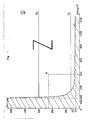
- a chromatographic resin with an average particle size G m of between 75 and 300 ⁇ m will be chosen corresponding in the diagram of FIG. 1 to the horizontal band comprised between the limit curve C and the two lines D i and D 2 . It turned out that there was interest in the dispersion of the grain size is not too large and a preliminary sieving of said resins will preferably be carried out to limit the dispersion to around 50% around the average value G m .
- the chromatographic resin is placed in a substantially vertical column comprising between 2 and 5 superimposed stages, successively traversed by the solution, the withdrawal of said solution being effected by overflow in the upper part of the 'upper floor, each floor (with the exception of the latter) being delimited by two perforated distribution systems, one distributing the solution at the base of the stage considered, the other distributing the solution to the stage situated immediately above.
- the process of the invention makes it possible both to achieve substantially the performance of fixed bed processes, while being freed from the serious defects of this type of bed: clogging and the need for cleaning, deterioration of the resins caused by compaction and cleaning.
- the fluidized bed allows the free passage of impurities from the solution without risk of clogging; no cleaning is necessary so that the service life of the resins is considerably increased.
- the process can be carried out continuously due to the absence of the constraints created by the cleanings: the chromatographic resin can be caused to flow continuously from top to bottom in the column, with a continuous supply of resin in upper part and continuous withdrawal in the lower part, the separation in a fluidized bed being carried out continuously in the column, with concomitant execution of washing, elution and washing operations outside the column.
- washing operations which consist of a simple rinsing with distilled water or other solution, or elution operation, which consists of passing a regeneration solution, with cleaning or unclogging operations should not be confused.
- elution operation which consists of passing a regeneration solution
- cleaning or unclogging operations should not be confused.
- the circulation of the chromatographic resin between two superposed stages can be ensured by a passage tube, arranged so as to allow the resin to circulate by overflow in said tube from the stage of the top to the stage of the bottom.
- one or more baffles are preferably placed on each stage in order to ensure complete renewal of the resin of the stage, without the appearance of dead zones.
- the process of the invention can, if necessary, be carried out batchwise: the chromatographic resin is then enclosed at each stage of the column in the absence of circulation from one stage to another, the separation in a fluidized bed being carried out by selective fixing cycles, washing, elution and washing in the column.
- This embodiment remains advantageous compared to separations in a fixed bed for the reasons already mentioned: in particular, it is not necessary to dismantle the column for cleaning.
- the column is advantageously supplied so that the solution flow inside it, is substantially constant at least during the selective fixing phases, the variation of this flow rate compared to its nominal value being less than T 5%.
- This arrangement guarantees stable fluidization of the chromatographic resin without risk of accidental entrainment of grains.
- the process of the invention is generally applicable for the separation of any biological macromolecule of molecular weight greater than 5000; the person skilled in the art is capable, in. each application, choose a selective chromatographic resin (density and particle size conditions provided by the diagram in Figure 1) and make a perforated distribution system suitable for the particle size of said resin (conditions already mentioned for diameters of open sections) .
- the method of the invention can be applied to the chromatographic separation of proteins from a whey;
- the resin used can in particular be a resin of the “Spherosil resin” type sold under this name by the company “Rhône Poulenc” and described in French patent No. 2,321,932; this resin meets the specifications provided by the diagram in Figure 1.
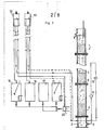
- the installation shown by way of example in FIGS. 2 and 3 is intended to ensure chromatographic separation of biological macromolecules according to a cyclic operating process, alternating a fixing phase, a washing phase, an elution phase and a new washing phase.
- the specific chromatographic resin is enclosed in a vertical column 1 with several stages, such as 3 or 4. Three or four stages may be provided in practice.
- Column 1 comprises a base 2 which makes it possible to distribute the solutions to the lower stage 3, through a perforated distribution system. This system is identical for all the floors and has been shown in 5 on an expanded scale in FIG. 3.
- the plates 6 and 7 are provided with perforations 6a and 7a and are positioned so that these perforations are offset by one plate relative to the neighboring plate.
- the density of distribution of the plates is such that the percentage of open sections is between 0.1 and 10% and, in particular equal to 5% in the examples described below.
- percentage of open sections means, as usual, the ratio in a cross section of the sum of the open areas to the useful surface of the plate.
- the perforations of each plate are provided so that each of them has a diameter greater than 300 kLm.
- the diameter of the perforations is adapted to the average particle size G m of the resin used: a value of the order of 4 G m to 6 G m seems to give the best results.
- G m average particle size
- plates having perforations with a diameter equal to 1 mm were used.
- the plates 6 and 7 are held on the edge by bolted annular flanges 9.
- the cylindrical elements 3 or 4 or base 2 are bonded at their periphery to the annular internal surfaces of these flanges.
- annular seals such as 10 provide peripheral sealing, on the one hand between plates, on the other hand between flanges and plates.
- the solution (solution to be treated during the fixing phase, distilled water solution during the washes or regeneration solution during the elution phase) enters the base 2 through a conduit 11.
- these solutions are placed in reservoirs 12 (solution to be treated or regeneration solution) and 13 (solution of distilled water) which are placed at an appropriate height above column 1 to deliver the desired flow rate.
- a flow meter 14 and a diaphragm 15 allow fine adjustment of this flow rate.
- the solution to be treated is stored in a tank 16 where it is stirred and kept at controlled temperature.
- the regeneration solution is stored under the same conditions in a tank 17.
- the distilled water is stored in a tank 18.
- the solution at the outlet of the column can be stored in a tank 19.
- a pump 20 and a system of conduits and valves allows the tanks 12 or 13 to be supplied at each phase with appropriate solutions from tanks 16-18, so that the level of the tanks is substantially constant.
- the system described above provides a supply to column 1 with a flow rate whose variations are in practice less than T5%.
- the liquid is collected by overflow in the upper part of the upper stage to be optionally stored in the tank 19.
- Figure 4 shows schematically a modified installation compared to the previous one to allow continuous operation.
- the column, its perforated distribution systems and the means for supplying liquid at constant flow are similar.
- the chromatographic resin is brought to circulate continuously from one stage to the lower stage and the washing and elution phases are carried out outside the column, the latter carrying out the chromatographic fixing in continued.
- a resin passage tube 21 is arranged which passes through the perforated distribution system. This tube extends between the upper part 21 a of the bed of the upper floor and the lower part 21 b of the bed of the lower floor.
- the resin can circulate by overflow in the various tubes 21, successively from one stage to that on the bottom.
- each passage tube 21 exceeds, at each stage, a height H B less than the height H s of the unoccupied portion of the stage considered.
- the fluidized resin bed which forms inside each tube 21 does not overflow from the tube on the upper stage, which constitutes the condition of gravity circulation of the resin from one stage to the stage inferior.
- a baffle 22 is disposed between the two orifices of the two tubes 21 which open onto the stage in question (lower orifice 21'b of the tube communicating with the upper stage and upper orifice 21 a of the communicating tube with the floor below).
- Each baffle 22 can be constituted by a tubular sleeve surrounding the tube 21; this sleeve extends in the upper part above the level of the orifice 21a and preserves in the lower part a passage 22a for the resin.
- the resin from the top floor and opening through the opening 21'b is less loaded and therefore generally lighter and tends to rise in the bed; the baffle 22 prevents the creation of a short circuit of resin between the orifices 21'b and 21a: it removes the dead zones of the bed where the resin would not be renewed and thus ensures a complete renewal thereof (it is note that, for certain resins and certain macromolecules to be fixed, the density of the resin does not change during the exchange: in this case, the baffle is less essential but improves the overall uniformity of fixing).
- the lower passage tube 23 passes through the supply base and is associated with hydraulic means for driving the resin 24, in the example towards a recovery tank 25.
- the resin from this tank is regenerated in an external column which can also operate in a fluidized bed; training towards this external column can be provided continuously.
- the regenerated chromatographic resin is placed in a storage tank 26, either by continuous transfer from the regeneration column, or by manual feeding.
- This hermetically closed tank is filled with distilled water and can be supplied with distilled water through a conduit 27 comprising a valve and a flow meter.
- the resin can be hydraulically transported through a tube 28 to a conveyor belt 29 which is associated with a vacuum pump in order to remove the water surrounding the resin grains.
- the mat 29 pours the regenerated resin, at an adjustable rate, into an upper passage tube 21 ", fitted with an upper funnel.
- Examples 1 and 2 were implemented on an installation of the type of that shown in FIG. 2 and Example 3 in an installation of the type of that shown in FIGS. 4 and 5.
- the installation column has three stages in this example; the height of each stage is 50 cm, the diameter of the column being 5 cm.
- the purpose of this example is to extract the albumin p-lactoglobulin (molecular mass in dietary form: 34,000) and ⁇ -lactalbumin (14,000) from a sweet whey, residue from the manufacture of cheese supplied by "Fromageries Bel".
- the chromatographic resin used is a “Spstedil QMA” resin manufactured by “Rhône Poulenc”.
- the initial particle size distribution is 100 to 300 ⁇ m. Dry sieving is carried out to retain the range of grains between 200 and 250 ⁇ m, ie an average particle size.
- G m 225 ⁇ m.
- the pair of values (G m , M v ) characterizing said resin is represented at point R on the diagram in FIG. 1.
- This resin is a chromatographic resin consisting of spherical grains of silica, having a specific surface of 25 m 2 / g, an average pore diameter of 125 nm (1250 ⁇ ) and a pore volume of 1 cm 3 / g, coated with a crosslinked polymer styrene vinyl triethoxysilane, carrying the functional groups:
- V mf 1.4 ⁇ 10 -4 m / s.
- the average diameter of the open sections of the distributor of each stage of the column corresponds in these conditions to approximately: 4 G m .
- the quantity of resin deposited on each stage is 130 c m 3 .
- the column is supplied at its base with whey, with a solution flow rate equal to 9 I / h not varying by more than 5% compared to this nominal value thanks to the nature of the supply means provided (tanks loaded fixed height).
- the bed in each floor undergoes an expansion of 64% and has a height of 20 cm. A good stable fluidization is visually observed.
- the whey has the following concentrations: 3.0 g / I in ( ⁇ -lactoglobulin and 1.2 g / I in ⁇ -lactalbumin.
- FIG. 7 represents the curves giving, as a function of time, the ratio of the concentrations at the exit of each stage C to the initial concentration Co: the curves ⁇ 1 ⁇ 2 and ⁇ 3 represent the variation of for a-lactalbumin, respectively at the exit of the lower stage. intermediate and upper.
- the ⁇ 1 curves. ⁇ 2 and ⁇ 3 represent the variation of for ⁇ -lactoglobulin respectively at the exit of the lower, intermediate and upper stage.
- the measurements were made on samples taken every 3 minutes, by zone electrophoresis on a cellulose acetate membrane.
- the resin is then eluted using a 0.1 N hydrochloric acid solution for 2 hours.
- a further washing with distilled water is then carried out for approximately 1 hour and the column is ready for a new cycle.
- the resin of the column is similarly fluidized.
- the amount of protein resulting from the elution phase is, for 0-lactoglobulin, 10.5 g which represents a fixation of 102 mg per gram of dry resin and, for ⁇ -lactalbumin, 1.7 g this which represents 16.5 mg per gram of dry resin.
- the eluate therefore contains 86.1% of ⁇ -lactoglobulin and 13.9% of ⁇ -lactalbumin.
- the relative proportions of these proteins in the starting product (whey) were 71% in ⁇ -lactoglobulin and 29% in ⁇ -lactalbumin. There is therefore an enrichment in ⁇ -lactoglobutin.
- the elution product containing these proteins is freed from the lactose, casein fines and mineral salts initially contained in the whey, the proteins being pure and in their native state (not denatured).
- Example 2 This example is carried out under the same conditions as Example 1, with the exception of the quantity of resin deposited on each stage which is 110 c m 3 .
- the whey has the same concentrations as in Example 1 (3.0 g / I in ⁇ -lactoglobulin and 1.2 g / I in ⁇ -lactalbumin).
- Figure 8 presents the curves giving, in as a function of time, the ratio of the concentrations at the outlet of each stage C to the initial concentration Co.
- the amount of protein obtained by elution corresponds to a fixation of 110 mg per gram of dry resin for ⁇ -lactoglobulin and 19.5 mg per g of dry resin for ⁇ -lactalbumin.
- the eluate therefore contains 84.9% of ⁇ -lactoglobulin and 15.1% of ⁇ -lactalbumin. With the exception of experimental and analytical errors, these proportions are similar to those observed for Example 1.
- This example aims to extract the albumin P-lactoglobulin and a-lactalbumin from a sweet whey, residue from cheese manufacturing, supplied by "Fromageries Bel".
- the resin used (“QMA spherosil”) has the same characteristics as in Example 1.
- the average diameter of the open distributor sections of each stage of the column is 4 G m .
- the flow rate of resin introduced into the column is maintained at 0.14 l / h.
- the resin evacuation system at the base of the column includes three electromagnetic valves controlled by a timer. Solid particles pass through the open upper valve and collect in a flexible plastic tube. Every 20 seconds, the upper valve is closed, while the side valve which opens at the same time as the lower valve injects distilled water which drives the particles down.
- the column is fed at its base with whey, with a flow rate of solution equal to 9 l / h, this flow rate being controlled in the same way as in Example 1.
- the bed in each stage has a height of 25 cm corresponding to the height of the overhang H B of the junction tube on the stage in question.
- Each stage has a height of 60.5 cm so that the height of the fluidized layer retained in the junction tube of the stage has a level lower than that of the fluidized layer of the immediately higher stage, thus preventing the resin overflow in the upper floor.
- the whey Upon entry, the whey has the following concentrations: 3.0 g / I in ⁇ -lactoglobulin and 1.2 g / I in ⁇ -lactalbumin.
- FIG. 9 represents the curves giving as a function of time, the ratio of the concentrations at the outlet of each stage C to the initial concentration Co.
- the operation includes a transitional phase before reaching the stationary operating regime.
- ⁇ -lactalbumin ( ⁇ 1 , ⁇ 2 , ⁇ 3 ) is retained in less quantity on the resin than ⁇ -lactoglobulin ( ⁇ 1 , ⁇ 2 , ( ⁇ 3 ).
- the liquid contains approximately 50% of initial ⁇ -lactalbumin while it contains only 25% of ⁇ -lactoglobulin, the rest being fixed on the resin.
Landscapes
- Chemical & Material Sciences (AREA)
- Analytical Chemistry (AREA)
- Life Sciences & Earth Sciences (AREA)
- Health & Medical Sciences (AREA)
- Organic Chemistry (AREA)
- Molecular Biology (AREA)
- Medicinal Chemistry (AREA)
- Genetics & Genomics (AREA)
- General Health & Medical Sciences (AREA)
- Biophysics (AREA)
- Proteomics, Peptides & Aminoacids (AREA)
- Biochemistry (AREA)
- Chemical Kinetics & Catalysis (AREA)
- Engineering & Computer Science (AREA)
- Food Science & Technology (AREA)
- Polymers & Plastics (AREA)
- Treatment Of Liquids With Adsorbents In General (AREA)
- Peptides Or Proteins (AREA)
Priority Applications (1)
| Application Number | Priority Date | Filing Date | Title |
|---|---|---|---|
| AT85202068T ATE42044T1 (de) | 1985-01-04 | 1985-12-13 | Verfahren zur chromatographischen trennung von biologischen makromolekuelen. |
Applications Claiming Priority (2)
| Application Number | Priority Date | Filing Date | Title |
|---|---|---|---|
| FR8500463 | 1985-01-04 | ||
| FR8500463A FR2575666B1 (fr) | 1985-01-04 | 1985-01-04 | Procede et dispositif pour la separation chromatographique de macromolecules biologiques |
Publications (2)
| Publication Number | Publication Date |
|---|---|
| EP0189611A1 EP0189611A1 (fr) | 1986-08-06 |
| EP0189611B1 true EP0189611B1 (fr) | 1989-04-12 |
Family
ID=9315250
Family Applications (1)
| Application Number | Title | Priority Date | Filing Date |
|---|---|---|---|
| EP85202068A Expired EP0189611B1 (fr) | 1985-01-04 | 1985-12-13 | Procédé pour la séparation chromatographique de macromolécules biologiques |
Country Status (12)
| Country | Link |
|---|---|
| US (1) | US4976865A (da) |
| EP (1) | EP0189611B1 (da) |
| AT (1) | ATE42044T1 (da) |
| AU (1) | AU577915B2 (da) |
| CA (1) | CA1278529C (da) |
| DE (1) | DE3569335D1 (da) |
| DK (1) | DK165391C (da) |
| ES (1) | ES8703288A1 (da) |
| FR (1) | FR2575666B1 (da) |
| IE (1) | IE58725B1 (da) |
| NO (1) | NO166148C (da) |
| NZ (1) | NZ214636A (da) |
Families Citing this family (21)
| Publication number | Priority date | Publication date | Assignee | Title |
|---|---|---|---|---|
| CH674315A5 (da) * | 1987-11-23 | 1990-05-31 | Werner Hafner | |
| FR2646993B1 (fr) * | 1989-05-19 | 1993-08-13 | Union Coop Agricole | Frloyer alain frdupont patrick maschine zum handhaben zerbrechlicher produkte, wie kaesebruch bei der herstellung von kaese. |
| SE9101149D0 (sv) * | 1991-04-17 | 1991-04-17 | Pharmacia Lkb Biotech | Beads for down stream processing |
| FI97277C (fi) * | 1993-01-25 | 1996-11-25 | Suomen Sokeri Oy | Kromatografinen erotuskolonni, sen sisärakenteet ja kromatografinen erotusmenetelmä |
| FI96225C (fi) | 1993-01-26 | 1996-05-27 | Cultor Oy | Menetelmä melassin fraktioimiseksi |
| US6663780B2 (en) | 1993-01-26 | 2003-12-16 | Danisco Finland Oy | Method for the fractionation of molasses |
| US6706188B2 (en) | 1993-05-03 | 2004-03-16 | Amersham Biociences Ab | Process and means for down stream processing |
| US5795398A (en) | 1994-09-30 | 1998-08-18 | Cultor Ltd. | Fractionation method of sucrose-containing solutions |
| US5902485A (en) | 1994-10-03 | 1999-05-11 | Amersham Pharmacia Biotech Ab | Access valve devices, their use in separation apparatus and corresponding methods |
| US6224776B1 (en) | 1996-05-24 | 2001-05-01 | Cultor Corporation | Method for fractionating a solution |
| SE9700383D0 (sv) * | 1997-02-04 | 1997-02-04 | Pharmacia Biotech Ab | An adsorption/separation method and a medium for adsorption/separation |
| US20020104801A1 (en) * | 1998-04-06 | 2002-08-08 | Nicolas Voute | Small dense microporous solid support materials, their preparation,and use for purification of large macromolecules and bioparticles |
| FI107115B (fi) | 1998-09-30 | 2001-06-15 | Valio Oy | Menetelmä naudan insuliinin poistamiseksi |
| CA2350690C (en) | 1998-10-31 | 2008-07-22 | Amersham Pharmacia Biotech Ab | A chromatographic process utilizing a fluidised bed |
| EP1175931A1 (en) * | 2000-07-25 | 2002-01-30 | Computer Cell Culture Center S.A. | Integration of high cell density bioreactor operation with ultra fast on-line downstream processing |
| EP1884274A1 (en) * | 2000-12-29 | 2008-02-06 | Upfront Chromatography A/S | Extracorporeal capturing of specific bio-macromolecular entities from extracellular body fluids |
| FI20010977L (fi) | 2001-05-09 | 2002-11-10 | Danisco Sweeteners Oy | Kromatografinen erotusmenetelmä |
| DE60203176T2 (de) * | 2001-06-01 | 2006-04-27 | Upfront Chromatography A/S, Kopenhagen | Fraktionierung von proteinhaltigen mischungen |
| EP1480524B1 (en) | 2002-03-07 | 2013-04-17 | Upfront Chromatography A/S | A process of isolating lactoferrin |
| US7094345B2 (en) * | 2002-09-09 | 2006-08-22 | Cytonome, Inc. | Implementation of microfluidic components, including molecular fractionation devices, in a microfluidic system |
| CZ2013885A3 (cs) * | 2013-11-15 | 2015-08-19 | Univerzita PalackĂ©ho | Způsob separace syrovátkových proteinů z mléčného média a zařízení k provádění tohoto způsobu |
Family Cites Families (14)
| Publication number | Priority date | Publication date | Assignee | Title |
|---|---|---|---|---|
| US2959542A (en) * | 1957-03-08 | 1960-11-08 | Dow Chemical Co | Continuous gas-lift ion-exchange process and apparatus |
| GB1070251A (en) * | 1962-10-19 | 1967-06-01 | Nat Res Dev | Improvements in and relating to solid/fluid contacting |
| GB1148661A (en) * | 1965-05-11 | 1969-04-16 | Victor Pretorius | Improvements relating to chromatography |
| DE1598049B2 (de) * | 1965-06-03 | 1972-04-06 | Boehringer Mannheim Gmbh, 6800 Mannheim | Verfahren und vorrichtung zur technischen durchfuehrung der saeulenchromatographie |
| GB1183833A (en) * | 1966-08-11 | 1970-03-11 | Victor Pretorious | Improvements in Chromatographic Processes and Apparatus. |
| US3549526A (en) * | 1968-01-31 | 1970-12-22 | Hart Brown | Contact process and apparatus |
| GB1422412A (en) * | 1972-01-24 | 1976-01-28 | Chiyoda Chem Eng Construct Co | Method of and apparatus for the continuous treatment of water using activated-carbon |
| US3928193A (en) * | 1975-02-14 | 1975-12-23 | Suomen Sokeri Oy | Process for large scale chromatography |
| FR2321932A1 (fr) * | 1975-08-28 | 1977-03-25 | Rhone Poulenc Ind | Procede de separation de proteines par echange d'ions |
| FR2359634A2 (fr) * | 1976-07-28 | 1978-02-24 | Rhone Poulenc Ind | Procede de separation de proteines par echange d'ions |
| US4100149A (en) * | 1975-08-28 | 1978-07-11 | Rhone-Poulenc Industries | Method of separating proteins by ion exchange |
| US4284511A (en) * | 1979-08-30 | 1981-08-18 | General Technology Applications, Inc. | Process for using magnetically ballasted sorbents |
| US4443231A (en) * | 1982-02-02 | 1984-04-17 | Exxon Research And Engineering Co. | Continuous chromatographic separations in a magnetically stabilized fluidized bed |
| US4675113A (en) * | 1984-11-28 | 1987-06-23 | University Patents, Inc. | Affinity chromatography using dried calcium alginate-magnetite separation media in a magnetically stabilized fluidized bed |
-
1985
- 1985-01-04 FR FR8500463A patent/FR2575666B1/fr not_active Expired
- 1985-12-13 DE DE8585202068T patent/DE3569335D1/de not_active Expired
- 1985-12-13 AT AT85202068T patent/ATE42044T1/de not_active IP Right Cessation
- 1985-12-13 EP EP85202068A patent/EP0189611B1/fr not_active Expired
- 1985-12-19 NZ NZ214636A patent/NZ214636A/xx unknown
- 1985-12-23 AU AU51612/85A patent/AU577915B2/en not_active Ceased
- 1985-12-27 NO NO855317A patent/NO166148C/no unknown
- 1985-12-31 ES ES550599A patent/ES8703288A1/es not_active Expired
-
1986
- 1986-01-03 CA CA000498947A patent/CA1278529C/fr not_active Expired - Lifetime
- 1986-01-03 DK DK002186A patent/DK165391C/da active
- 1986-01-03 IE IE1286A patent/IE58725B1/en not_active IP Right Cessation
-
1987
- 1987-10-22 US US07/112,312 patent/US4976865A/en not_active Expired - Fee Related
Also Published As
| Publication number | Publication date |
|---|---|
| IE58725B1 (en) | 1993-11-03 |
| ES8703288A1 (es) | 1987-03-01 |
| DE3569335D1 (en) | 1989-05-18 |
| DK165391C (da) | 1993-04-13 |
| NO166148B (no) | 1991-02-25 |
| NZ214636A (en) | 1989-01-06 |
| ES550599A0 (es) | 1987-03-01 |
| NO166148C (no) | 1991-06-05 |
| NO855317L (no) | 1986-07-07 |
| DK165391B (da) | 1992-11-23 |
| AU577915B2 (en) | 1988-10-06 |
| ATE42044T1 (de) | 1989-04-15 |
| EP0189611A1 (fr) | 1986-08-06 |
| US4976865A (en) | 1990-12-11 |
| FR2575666B1 (fr) | 1989-08-18 |
| IE860012L (en) | 1986-07-04 |
| DK2186A (da) | 1986-07-05 |
| AU5161285A (en) | 1986-07-10 |
| DK2186D0 (da) | 1986-01-03 |
| CA1278529C (fr) | 1991-01-02 |
| FR2575666A1 (fr) | 1986-07-11 |
Similar Documents
| Publication | Publication Date | Title |
|---|---|---|
| EP0189611B1 (fr) | Procédé pour la séparation chromatographique de macromolécules biologiques | |
| Dechow et al. | Separation and purification techniques in biotechnology | |
| EP0640124B1 (fr) | Dispositif du type reacteur a volume variable et procede de culture de material cellulaire | |
| FR2470635A1 (fr) | Procede et appareil pour le traitement, notamment l'enrobage ou l'agrandissement, de particules ou granules | |
| FR2714299A1 (fr) | Méthode de séparation d'affinité, particules d'affinité et méthode pour mettre ces particules d'affinité à la taille. | |
| JP2001518003A (ja) | クロマトグラフ疑似移動床プロセスによる溶液分別方法 | |
| JP2002532730A (ja) | 分子サイズによる物質の連続分離方法 | |
| CA1257221A (fr) | Procede et installation d'electrolyse par percolation a travers une ou des electrodes volumiques poreuses | |
| FR2543012A1 (da) | ||
| FR2555462A1 (fr) | Procede de concentration d'une suspension de particules microscopiques, dispositif pour la mise en oeuvre de ce procede et applications de celui-ci | |
| US20260091368A1 (en) | System and method of applied radial technology chromatography | |
| FR2545375A1 (fr) | Dispositif destine a la separation de substances troubles a partir de liquides et procede destine a une telle separation | |
| JPH0810507A (ja) | 物質の連続的分離及び精製 | |
| Verma et al. | Separation Technologies: Filtration and Centrifugation for Food and Dairy Processing | |
| CN1043883A (zh) | 利用颗粒性材料从液体中分离物质的方法 | |
| FR2559500A1 (fr) | Procede de culture de cellules avec barbotage d'un gaz | |
| WO2011004129A1 (fr) | Utilisation d'un coproduit issu d'un procede d'extraction du lysozyme a partir de blanc d'oeuf, pour l'obtention d'au moins une proteine basique de blanc d'oeuf | |
| NZ207619A (en) | Hydrolysis of lactose in whey | |
| Wan et al. | Fractionation of bovine serum albumin and monoclonal antibody alemtuzumab using carrier phase ultrafiltration | |
| US4936919A (en) | Method of and device for continuously swelling starchy raw materials | |
| JPS61225197A (ja) | 生体高分子のクロマトグラフィー分離方法 | |
| FR2560188A1 (fr) | Procede de separation de la phenylalanine et de l'acide cinnamique | |
| BE639246A (da) | ||
| Chen-Wu et al. | Apparatus and method for separation of biological agents | |
| JPS62294409A (ja) | 回転円板連続ろ過機 |
Legal Events
| Date | Code | Title | Description |
|---|---|---|---|
| PUAI | Public reference made under article 153(3) epc to a published international application that has entered the european phase |
Free format text: ORIGINAL CODE: 0009012 |
|
| AK | Designated contracting states |
Kind code of ref document: A1 Designated state(s): AT BE CH DE FR GB IT LI LU NL SE |
|
| 17P | Request for examination filed |
Effective date: 19861210 |
|
| RAP1 | Party data changed (applicant data changed or rights of an application transferred) |
Owner name: ETABLISSEMENT PUBLIC DIT: CENTRE NATIONAL DE LA R |
|
| 17Q | First examination report despatched |
Effective date: 19880204 |
|
| GRAA | (expected) grant |
Free format text: ORIGINAL CODE: 0009210 |
|
| AK | Designated contracting states |
Kind code of ref document: B1 Designated state(s): AT BE CH DE FR GB IT LI LU NL SE |
|
| REF | Corresponds to: |
Ref document number: 42044 Country of ref document: AT Date of ref document: 19890415 Kind code of ref document: T |
|
| REF | Corresponds to: |
Ref document number: 3569335 Country of ref document: DE Date of ref document: 19890518 |
|
| GBT | Gb: translation of ep patent filed (gb section 77(6)(a)/1977) | ||
| ITF | It: translation for a ep patent filed | ||
| PLBE | No opposition filed within time limit |
Free format text: ORIGINAL CODE: 0009261 |
|
| STAA | Information on the status of an ep patent application or granted ep patent |
Free format text: STATUS: NO OPPOSITION FILED WITHIN TIME LIMIT |
|
| 26N | No opposition filed | ||
| ITTA | It: last paid annual fee | ||
| EPTA | Lu: last paid annual fee | ||
| EAL | Se: european patent in force in sweden |
Ref document number: 85202068.4 |
|
| PGFP | Annual fee paid to national office [announced via postgrant information from national office to epo] |
Ref country code: LU Payment date: 19951201 Year of fee payment: 11 |
|
| PGFP | Annual fee paid to national office [announced via postgrant information from national office to epo] |
Ref country code: SE Payment date: 19951207 Year of fee payment: 11 |
|
| PGFP | Annual fee paid to national office [announced via postgrant information from national office to epo] |
Ref country code: GB Payment date: 19951211 Year of fee payment: 11 |
|
| PGFP | Annual fee paid to national office [announced via postgrant information from national office to epo] |
Ref country code: FR Payment date: 19951222 Year of fee payment: 11 |
|
| PGFP | Annual fee paid to national office [announced via postgrant information from national office to epo] |
Ref country code: CH Payment date: 19951228 Year of fee payment: 11 |
|
| PGFP | Annual fee paid to national office [announced via postgrant information from national office to epo] |
Ref country code: BE Payment date: 19951229 Year of fee payment: 11 Ref country code: AT Payment date: 19951229 Year of fee payment: 11 |
|
| PGFP | Annual fee paid to national office [announced via postgrant information from national office to epo] |
Ref country code: NL Payment date: 19951230 Year of fee payment: 11 |
|
| PGFP | Annual fee paid to national office [announced via postgrant information from national office to epo] |
Ref country code: DE Payment date: 19960229 Year of fee payment: 11 |
|
| PG25 | Lapsed in a contracting state [announced via postgrant information from national office to epo] |
Ref country code: LU Free format text: LAPSE BECAUSE OF NON-PAYMENT OF DUE FEES Effective date: 19961213 Ref country code: GB Effective date: 19961213 Ref country code: AT Effective date: 19961213 |
|
| PG25 | Lapsed in a contracting state [announced via postgrant information from national office to epo] |
Ref country code: SE Effective date: 19961214 |
|
| PG25 | Lapsed in a contracting state [announced via postgrant information from national office to epo] |
Ref country code: LI Effective date: 19961231 Ref country code: CH Effective date: 19961231 Ref country code: BE Effective date: 19961231 |
|
| BERE | Be: lapsed |
Owner name: CENTRE NATIONAL DE LA RECHERCHE SCIENTIFIQUE CNRS Effective date: 19961231 |
|
| PG25 | Lapsed in a contracting state [announced via postgrant information from national office to epo] |
Ref country code: NL Effective date: 19970701 |
|
| GBPC | Gb: european patent ceased through non-payment of renewal fee |
Effective date: 19961213 |
|
| REG | Reference to a national code |
Ref country code: CH Ref legal event code: PL |
|
| PG25 | Lapsed in a contracting state [announced via postgrant information from national office to epo] |
Ref country code: FR Effective date: 19970829 |
|
| NLV4 | Nl: lapsed or anulled due to non-payment of the annual fee |
Effective date: 19970701 |
|
| PG25 | Lapsed in a contracting state [announced via postgrant information from national office to epo] |
Ref country code: DE Effective date: 19970902 |
|
| EUG | Se: european patent has lapsed |
Ref document number: 85202068.4 |
|
| REG | Reference to a national code |
Ref country code: FR Ref legal event code: ST |