EP0189648A1 - Procédé pour cracking hydrogénant et déparaffinage catalytique - Google Patents
Procédé pour cracking hydrogénant et déparaffinage catalytique Download PDFInfo
- Publication number
- EP0189648A1 EP0189648A1 EP85308595A EP85308595A EP0189648A1 EP 0189648 A1 EP0189648 A1 EP 0189648A1 EP 85308595 A EP85308595 A EP 85308595A EP 85308595 A EP85308595 A EP 85308595A EP 0189648 A1 EP0189648 A1 EP 0189648A1
- Authority
- EP
- European Patent Office
- Prior art keywords
- stream
- heavy
- hydrocracking
- product
- dewaxing
- Prior art date
- Legal status (The legal status is an assumption and is not a legal conclusion. Google has not performed a legal analysis and makes no representation as to the accuracy of the status listed.)
- Granted
Links
- 238000004517 catalytic hydrocracking Methods 0.000 title claims abstract description 64
- 238000000034 method Methods 0.000 title claims abstract description 50
- 230000003197 catalytic effect Effects 0.000 title claims abstract description 36
- 239000000446 fuel Substances 0.000 claims abstract description 53
- 239000010763 heavy fuel oil Substances 0.000 claims abstract description 41
- 229930195733 hydrocarbon Natural products 0.000 claims description 59
- 150000002430 hydrocarbons Chemical class 0.000 claims description 58
- 238000009835 boiling Methods 0.000 claims description 45
- UFHFLCQGNIYNRP-UHFFFAOYSA-N Hydrogen Chemical compound [H][H] UFHFLCQGNIYNRP-UHFFFAOYSA-N 0.000 claims description 34
- 239000001257 hydrogen Substances 0.000 claims description 34
- 229910052739 hydrogen Inorganic materials 0.000 claims description 34
- 239000003921 oil Substances 0.000 claims description 34
- 239000007789 gas Substances 0.000 claims description 30
- 239000004215 Carbon black (E152) Substances 0.000 claims description 22
- 239000003350 kerosene Substances 0.000 claims description 18
- 238000004519 manufacturing process Methods 0.000 abstract description 9
- 239000000295 fuel oil Substances 0.000 abstract description 8
- 239000010771 distillate fuel oil Substances 0.000 abstract description 7
- 239000000047 product Substances 0.000 description 63
- 239000010457 zeolite Substances 0.000 description 47
- 239000003054 catalyst Substances 0.000 description 39
- 239000011148 porous material Substances 0.000 description 34
- 238000004821 distillation Methods 0.000 description 25
- 229910021536 Zeolite Inorganic materials 0.000 description 23
- HNPSIPDUKPIQMN-UHFFFAOYSA-N dioxosilane;oxo(oxoalumanyloxy)alumane Chemical compound O=[Si]=O.O=[Al]O[Al]=O HNPSIPDUKPIQMN-UHFFFAOYSA-N 0.000 description 23
- VLKZOEOYAKHREP-UHFFFAOYSA-N n-Hexane Chemical compound CCCCCC VLKZOEOYAKHREP-UHFFFAOYSA-N 0.000 description 15
- VYPSYNLAJGMNEJ-UHFFFAOYSA-N Silicium dioxide Chemical compound O=[Si]=O VYPSYNLAJGMNEJ-UHFFFAOYSA-N 0.000 description 13
- 239000003502 gasoline Substances 0.000 description 11
- IJGRMHOSHXDMSA-UHFFFAOYSA-N Atomic nitrogen Chemical group N#N IJGRMHOSHXDMSA-UHFFFAOYSA-N 0.000 description 10
- PXHVJJICTQNCMI-UHFFFAOYSA-N Nickel Chemical compound [Ni] PXHVJJICTQNCMI-UHFFFAOYSA-N 0.000 description 10
- PNEYBMLMFCGWSK-UHFFFAOYSA-N aluminium oxide Inorganic materials [O-2].[O-2].[O-2].[Al+3].[Al+3] PNEYBMLMFCGWSK-UHFFFAOYSA-N 0.000 description 8
- 229910052751 metal Inorganic materials 0.000 description 8
- 239000002184 metal Substances 0.000 description 8
- 238000005336 cracking Methods 0.000 description 7
- 238000012360 testing method Methods 0.000 description 7
- 150000001875 compounds Chemical class 0.000 description 6
- 230000000694 effects Effects 0.000 description 6
- 239000000377 silicon dioxide Substances 0.000 description 6
- 239000006227 byproduct Substances 0.000 description 5
- 238000004523 catalytic cracking Methods 0.000 description 5
- 238000010586 diagram Methods 0.000 description 5
- 238000005984 hydrogenation reaction Methods 0.000 description 5
- 239000007788 liquid Substances 0.000 description 5
- 239000000463 material Substances 0.000 description 5
- 229910052759 nickel Inorganic materials 0.000 description 5
- 229910052757 nitrogen Inorganic materials 0.000 description 5
- TVMXDCGIABBOFY-UHFFFAOYSA-N octane Chemical compound CCCCCCCC TVMXDCGIABBOFY-UHFFFAOYSA-N 0.000 description 5
- BASFCYQUMIYNBI-UHFFFAOYSA-N platinum Chemical compound [Pt] BASFCYQUMIYNBI-UHFFFAOYSA-N 0.000 description 5
- KDLHZDBZIXYQEI-UHFFFAOYSA-N Palladium Chemical compound [Pd] KDLHZDBZIXYQEI-UHFFFAOYSA-N 0.000 description 4
- NINIDFKCEFEMDL-UHFFFAOYSA-N Sulfur Chemical group [S] NINIDFKCEFEMDL-UHFFFAOYSA-N 0.000 description 4
- MCMNRKCIXSYSNV-UHFFFAOYSA-N Zirconium dioxide Chemical compound O=[Zr]=O MCMNRKCIXSYSNV-UHFFFAOYSA-N 0.000 description 4
- 239000010687 lubricating oil Substances 0.000 description 4
- 150000002739 metals Chemical class 0.000 description 4
- 229910000510 noble metal Inorganic materials 0.000 description 4
- 239000011593 sulfur Chemical group 0.000 description 4
- 229910052717 sulfur Chemical group 0.000 description 4
- UHOVQNZJYSORNB-UHFFFAOYSA-N Benzene Chemical compound C1=CC=CC=C1 UHOVQNZJYSORNB-UHFFFAOYSA-N 0.000 description 3
- YXFVVABEGXRONW-UHFFFAOYSA-N Toluene Chemical compound CC1=CC=CC=C1 YXFVVABEGXRONW-UHFFFAOYSA-N 0.000 description 3
- 239000002253 acid Substances 0.000 description 3
- 230000032683 aging Effects 0.000 description 3
- 231100000614 poison Toxicity 0.000 description 3
- 238000012545 processing Methods 0.000 description 3
- AUHZEENZYGFFBQ-UHFFFAOYSA-N 1,3,5-trimethylbenzene Chemical compound CC1=CC(C)=CC(C)=C1 AUHZEENZYGFFBQ-UHFFFAOYSA-N 0.000 description 2
- PFEOZHBOMNWTJB-UHFFFAOYSA-N 3-methylpentane Chemical compound CCC(C)CC PFEOZHBOMNWTJB-UHFFFAOYSA-N 0.000 description 2
- ZOKXTWBITQBERF-UHFFFAOYSA-N Molybdenum Chemical compound [Mo] ZOKXTWBITQBERF-UHFFFAOYSA-N 0.000 description 2
- 150000001336 alkenes Chemical class 0.000 description 2
- 230000029936 alkylation Effects 0.000 description 2
- 238000005804 alkylation reaction Methods 0.000 description 2
- 125000000129 anionic group Chemical class 0.000 description 2
- 125000004432 carbon atom Chemical group C* 0.000 description 2
- 238000006555 catalytic reaction Methods 0.000 description 2
- 125000002091 cationic group Chemical class 0.000 description 2
- 238000006243 chemical reaction Methods 0.000 description 2
- 239000010779 crude oil Substances 0.000 description 2
- 230000005484 gravity Effects 0.000 description 2
- 238000002156 mixing Methods 0.000 description 2
- 239000002808 molecular sieve Substances 0.000 description 2
- 229910052750 molybdenum Inorganic materials 0.000 description 2
- 239000011733 molybdenum Substances 0.000 description 2
- 229910052680 mordenite Inorganic materials 0.000 description 2
- 229910052763 palladium Inorganic materials 0.000 description 2
- 229910052697 platinum Inorganic materials 0.000 description 2
- 230000007096 poisonous effect Effects 0.000 description 2
- UOHMMEJUHBCKEE-UHFFFAOYSA-N prehnitene Chemical compound CC1=CC=C(C)C(C)=C1C UOHMMEJUHBCKEE-UHFFFAOYSA-N 0.000 description 2
- 238000000926 separation method Methods 0.000 description 2
- URGAHOPLAPQHLN-UHFFFAOYSA-N sodium aluminosilicate Chemical compound [Na+].[Al+3].[O-][Si]([O-])=O.[O-][Si]([O-])=O URGAHOPLAPQHLN-UHFFFAOYSA-N 0.000 description 2
- 238000001179 sorption measurement Methods 0.000 description 2
- 238000003860 storage Methods 0.000 description 2
- CBXCPBUEXACCNR-UHFFFAOYSA-N tetraethylammonium Chemical compound CC[N+](CC)(CC)CC CBXCPBUEXACCNR-UHFFFAOYSA-N 0.000 description 2
- QEMXHQIAXOOASZ-UHFFFAOYSA-N tetramethylammonium Chemical compound C[N+](C)(C)C QEMXHQIAXOOASZ-UHFFFAOYSA-N 0.000 description 2
- WFKWXMTUELFFGS-UHFFFAOYSA-N tungsten Chemical compound [W] WFKWXMTUELFFGS-UHFFFAOYSA-N 0.000 description 2
- 229910052721 tungsten Inorganic materials 0.000 description 2
- 239000010937 tungsten Substances 0.000 description 2
- VYZAMTAEIAYCRO-UHFFFAOYSA-N Chromium Chemical compound [Cr] VYZAMTAEIAYCRO-UHFFFAOYSA-N 0.000 description 1
- RYGMFSIKBFXOCR-UHFFFAOYSA-N Copper Chemical compound [Cu] RYGMFSIKBFXOCR-UHFFFAOYSA-N 0.000 description 1
- XDTMQSROBMDMFD-UHFFFAOYSA-N Cyclohexane Chemical compound C1CCCCC1 XDTMQSROBMDMFD-UHFFFAOYSA-N 0.000 description 1
- DGAQECJNVWCQMB-PUAWFVPOSA-M Ilexoside XXIX Chemical compound C[C@@H]1CC[C@@]2(CC[C@@]3(C(=CC[C@H]4[C@]3(CC[C@@H]5[C@@]4(CC[C@@H](C5(C)C)OS(=O)(=O)[O-])C)C)[C@@H]2[C@]1(C)O)C)C(=O)O[C@H]6[C@@H]([C@H]([C@@H]([C@H](O6)CO)O)O)O.[Na+] DGAQECJNVWCQMB-PUAWFVPOSA-M 0.000 description 1
- BPQQTUXANYXVAA-UHFFFAOYSA-N Orthosilicate Chemical compound [O-][Si]([O-])([O-])[O-] BPQQTUXANYXVAA-UHFFFAOYSA-N 0.000 description 1
- 229910019142 PO4 Inorganic materials 0.000 description 1
- KJTLSVCANCCWHF-UHFFFAOYSA-N Ruthenium Chemical compound [Ru] KJTLSVCANCCWHF-UHFFFAOYSA-N 0.000 description 1
- HCHKCACWOHOZIP-UHFFFAOYSA-N Zinc Chemical compound [Zn] HCHKCACWOHOZIP-UHFFFAOYSA-N 0.000 description 1
- 230000002378 acidificating effect Effects 0.000 description 1
- 150000001335 aliphatic alkanes Chemical class 0.000 description 1
- 229910000323 aluminium silicate Inorganic materials 0.000 description 1
- 125000003118 aryl group Chemical group 0.000 description 1
- QVGXLLKOCUKJST-UHFFFAOYSA-N atomic oxygen Chemical group [O] QVGXLLKOCUKJST-UHFFFAOYSA-N 0.000 description 1
- 239000010953 base metal Substances 0.000 description 1
- 239000011230 binding agent Substances 0.000 description 1
- UNYSKUBLZGJSLV-UHFFFAOYSA-L calcium;1,3,5,2,4,6$l^{2}-trioxadisilaluminane 2,4-dioxide;dihydroxide;hexahydrate Chemical compound O.O.O.O.O.O.[OH-].[OH-].[Ca+2].O=[Si]1O[Al]O[Si](=O)O1.O=[Si]1O[Al]O[Si](=O)O1 UNYSKUBLZGJSLV-UHFFFAOYSA-L 0.000 description 1
- 229910052799 carbon Inorganic materials 0.000 description 1
- 229910052676 chabazite Inorganic materials 0.000 description 1
- 229910052804 chromium Inorganic materials 0.000 description 1
- 239000011651 chromium Substances 0.000 description 1
- 229910017052 cobalt Inorganic materials 0.000 description 1
- 239000010941 cobalt Substances 0.000 description 1
- GUTLYIVDDKVIGB-UHFFFAOYSA-N cobalt atom Chemical compound [Co] GUTLYIVDDKVIGB-UHFFFAOYSA-N 0.000 description 1
- 229910052802 copper Inorganic materials 0.000 description 1
- 239000010949 copper Substances 0.000 description 1
- 239000013078 crystal Substances 0.000 description 1
- 229910002026 crystalline silica Inorganic materials 0.000 description 1
- 229910052675 erionite Inorganic materials 0.000 description 1
- 239000012530 fluid Substances 0.000 description 1
- 238000004231 fluid catalytic cracking Methods 0.000 description 1
- 125000005842 heteroatom Chemical group 0.000 description 1
- YUWFEBAXEOLKSG-UHFFFAOYSA-N hexamethylbenzene Chemical compound CC1=C(C)C(C)=C(C)C(C)=C1C YUWFEBAXEOLKSG-UHFFFAOYSA-N 0.000 description 1
- 238000005470 impregnation Methods 0.000 description 1
- 229910052741 iridium Inorganic materials 0.000 description 1
- GKOZUEZYRPOHIO-UHFFFAOYSA-N iridium atom Chemical compound [Ir] GKOZUEZYRPOHIO-UHFFFAOYSA-N 0.000 description 1
- 150000002605 large molecules Chemical class 0.000 description 1
- IVSZLXZYQVIEFR-UHFFFAOYSA-N m-xylene Chemical group CC1=CC=CC(C)=C1 IVSZLXZYQVIEFR-UHFFFAOYSA-N 0.000 description 1
- 229920002521 macromolecule Polymers 0.000 description 1
- 238000005259 measurement Methods 0.000 description 1
- 125000002496 methyl group Chemical group [H]C([H])([H])* 0.000 description 1
- 239000000203 mixture Substances 0.000 description 1
- 230000007935 neutral effect Effects 0.000 description 1
- MOWMLACGTDMJRV-UHFFFAOYSA-N nickel tungsten Chemical compound [Ni].[W] MOWMLACGTDMJRV-UHFFFAOYSA-N 0.000 description 1
- 229910017464 nitrogen compound Inorganic materials 0.000 description 1
- 150000002830 nitrogen compounds Chemical class 0.000 description 1
- 229910052760 oxygen Inorganic materials 0.000 description 1
- 239000001301 oxygen Substances 0.000 description 1
- 239000012188 paraffin wax Substances 0.000 description 1
- 239000003208 petroleum Substances 0.000 description 1
- 235000021317 phosphate Nutrition 0.000 description 1
- 150000003013 phosphoric acid derivatives Chemical class 0.000 description 1
- 239000002574 poison Substances 0.000 description 1
- 239000000376 reactant Substances 0.000 description 1
- 238000007670 refining Methods 0.000 description 1
- 229910052702 rhenium Inorganic materials 0.000 description 1
- WUAPFZMCVAUBPE-UHFFFAOYSA-N rhenium atom Chemical compound [Re] WUAPFZMCVAUBPE-UHFFFAOYSA-N 0.000 description 1
- 229910052703 rhodium Inorganic materials 0.000 description 1
- 239000010948 rhodium Substances 0.000 description 1
- MHOVAHRLVXNVSD-UHFFFAOYSA-N rhodium atom Chemical compound [Rh] MHOVAHRLVXNVSD-UHFFFAOYSA-N 0.000 description 1
- 229910052707 ruthenium Inorganic materials 0.000 description 1
- 239000003079 shale oil Substances 0.000 description 1
- 235000012239 silicon dioxide Nutrition 0.000 description 1
- 229910052708 sodium Inorganic materials 0.000 description 1
- 239000011734 sodium Substances 0.000 description 1
- 230000006641 stabilisation Effects 0.000 description 1
- 238000011105 stabilization Methods 0.000 description 1
- 238000010561 standard procedure Methods 0.000 description 1
- 238000010998 test method Methods 0.000 description 1
- 150000003568 thioethers Chemical class 0.000 description 1
- IMFACGCPASFAPR-UHFFFAOYSA-N tributylamine Chemical compound CCCCN(CCCC)CCCC IMFACGCPASFAPR-UHFFFAOYSA-N 0.000 description 1
- 238000010977 unit operation Methods 0.000 description 1
- 238000005292 vacuum distillation Methods 0.000 description 1
- 239000011800 void material Substances 0.000 description 1
- 239000001993 wax Substances 0.000 description 1
- 229910052725 zinc Inorganic materials 0.000 description 1
- 239000011701 zinc Substances 0.000 description 1
Images

Classifications
-
- C—CHEMISTRY; METALLURGY
- C10—PETROLEUM, GAS OR COKE INDUSTRIES; TECHNICAL GASES CONTAINING CARBON MONOXIDE; FUELS; LUBRICANTS; PEAT
- C10G—CRACKING HYDROCARBON OILS; PRODUCTION OF LIQUID HYDROCARBON MIXTURES, e.g. BY DESTRUCTIVE HYDROGENATION, OLIGOMERISATION, POLYMERISATION; RECOVERY OF HYDROCARBON OILS FROM OIL-SHALE, OIL-SAND, OR GASES; REFINING MIXTURES MAINLY CONSISTING OF HYDROCARBONS; REFORMING OF NAPHTHA; MINERAL WAXES
- C10G65/00—Treatment of hydrocarbon oils by two or more hydrotreatment processes only
- C10G65/02—Treatment of hydrocarbon oils by two or more hydrotreatment processes only plural serial stages only
- C10G65/12—Treatment of hydrocarbon oils by two or more hydrotreatment processes only plural serial stages only including cracking steps and other hydrotreatment steps
Definitions
- This invention relates to a hydrocarbon conversion process for the increased production of fuels in a refinery by combining hydrocracking and catalytic dewaxing steps, and more particularly, to a process to increase jet fuel, distillate or low pour heavy fuel oil yields.
- catalytic hydrodewaxing in which gas oil is contacted with hydrogen and a shape-selective catalyst to selectively crack or hydrocrack the paraffinic molecules in the gas oil.
- the catalysts were those cracking zeolite catalysts which had pore openings that would admit and crack only normal paraffins and exclude all other gas oil components, for example, erionite-type zeolites.
- U.S. Patent Re. 28,398 describes an improvement to such a process by substituting a ZSM-5-type zeolite for the previously used er i onite-type cracking zeolite catalysts.
- the product of hydrodewaxing gas oil may be suitably fractionated to produce high yields of dewaxed gas oil boiling in the same range as the feed, some naphtha and some light (C; )hydrocarbons.
- Catalytic dewaxing with a ZSM-5-type zeolite may be employed to improve the quality of a variety of feedstocks.
- U.S. Patent Re. 28,398 describes in addition to gas oil other useful feedstocks including crude oil, full range dehydrated shale oil and lube oil stocks.
- U. S. Patents 3,893,906 and 3,894,939 teach that a mixture of gas oil and aromatic naphtha yield a lower pour point gas oil and a higher octane gasoline when subjected to such catalytic hydrodewaxing.
- U. S. Patent 3,989,617 describes an improved process for catalytically treating lubricating oil base stocks with ZSM-5-type zeolites.
- U. S. Patents 3,755,145, 3,852,189, 3,894,938 and 3,956,102 describe other improvements in this process when used alone or in combination with other processes.
- the desired low pour point fuel oil is recovered as the bottoms with the tower overhead of about 400°F- hydrocarbons comprising C4 and lighter gaseous products plus hydrocarbons in the gasoline boiling range.
- That combination process is practiced in two complete processing units: the catalytic cracker with all its usual attendant equipment including a fractionator, and a catalytic hydrodewaxer with its usual attendant equipment, including a fractionator.
- these units may be operated in combination or separately.
- U. S. Patent 4,332,670 describes a process in which the fractionating and stripping equipment of a middle distillate catalytic dewaxing unit may be eliminated by integrating the catalytic dewaxing unit with a catalytic cracking unit
- U. S. Patent 4,283,271 describes another combination to upgrade lubricating oils comprising a combination process in which a hydrocarbon feed sequentially passes through a hydrocracking zone, a catalytic dewaxing zone, and a hydrotreating zone, all at high pressure. Hydrocracked product is separated from recycle hydrogen prior to dewaxing.
- U. S. Patents 4,347,121 and 4,325,805 describe other aspects of the combination process to produce lubricating oils by combining dewaxing and hydrocracking.
- non-hydrocracked heavy gas oil may be sold as fuel oil, sent to a coker to make gasoline, sent to a hydrocracker, sent to a fluid catalytic cracking unit or sent to thermofor catalytic cracking unit
- a heavy gas oil stream is hydrocracked, the resultant hydrocracked product may be unstable in the presence of air thus requiring some stabilization process such as hydrofinishing.
- Another disadvantage of hydrocracked heavy gas oil is that hydrocracking results in a high pour point hydrocracked product Thus, if the hydrocracked product is distilled into its different cuts, the products tend to have high pour points thus reducing the amounts of useful products and reducing the selectivity to determine which products will be obtained.
- the present invention is based on the observation that the selectivity of products from a heavy gas oil feedstock can be increased by combining hydrocracking and catalytic dewaxing.
- Hydrocracking is a process to convert a feedstock such as heavy fuel oil into naphtha, kerosene and distillate and remove heteroatoms such as oxygen, nitrogen or sulfur.
- a heavy fuel oil product may be obtained if the hydrocracker effluent stream is not recycled to produce lighter products.
- the Mobil distillate dewaxing (MDDW) process allows the refiner to improve specified product fluidity properties - (freeze point, pour point cloud point and CFPP (cold filter plugging point)) of a jet fuel, distillate or heavy fuel oil.
- CFFP is a test procedure in which oil is put through filter paper and. the temperature at which it plugs is measured. Usually, the CFFP temperature is between the cloud and pour points.
- a heavy gas oil feedstock is hydrocracked to yield a hydrocracked product which is distilled to produce a lighter boiling range stream and a relatively heavier boiling range stream.
- the lighter boiling range stream is the normal refinery product stream.
- the process of the invention comprises selectively increasing the yield of a hydrocarbon product from a heavy gas oil hydrocarbon feedstock by:
- the process may employ any dewaxing catalyst, such as one comprising a large pore or medium pore zeolite.
- the most suitable catalyst is determined by feedstock characteristics and operating conditions.
- the process may be operated to selectively increase the yield of either jet fuel, distillate or heavy fuel oil.
- the process may catalytically dewax a feedstock, then hydrocrack, and subsequently distill the dewaxed feedstock to desired products.
- the process may include sequential hydrocracking, dewaxing, subsequent hydrocracking and distillation to produce the desired products.
- the dewaxing effluent can be hydrotreated to remove sulfur and saturate aromatics and then blended with a normal product stream.
- the hydrocracking step may be distinguished from a hydrotreating step by the amount of hydrogen consumed.
- the hydrocracking step typically consuming about 1000 to about 2000 SCF/bbl, while the hydrotreating step consumes only about 100 to about 200 SCF/bbl.
- the process In addition to selectively increasing the yields of jet fuel, distillate or heavy fuel oil, the process also increases the production of high octane MDDW gasoline by-product, increases the production of C 3 /C 4 olefinic by-product streams from MDDW for possible use in alkylation or petrochemical processes, and increases the BTU/gallon content in both the jet fuel and distillate fuels which may increase product value.
- An advantage of the process in which catalytic dewaxing precedes hydrocracking is that it may allow use of a smaller hydrocracking unit.
- the advantage of the process in which hydrocracking precedes catalytic dewaxing is that the hydrocracking reduces the levels of nitrogen in the feedstock so the feedstock is relatively easy to dewax, and thus results in very long dewaxing cycles.
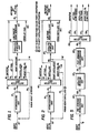
- Fig. 1 shows a hydrocracking/cataiytic dewaxing flow scheme arrangement for selectively producing jet fuel.
- a heavy gas oil stream passes through conduit 10 to a hydrocracking unit 20 to produce a hydrocracked product 22.
- the heavy gas oil comes from a vacuum distillation tower (not shown).
- the hydrocracking unit 20 operates at a space velocity of 0.2 5 to 3 Liquid Hourly Space Velocity (LHSV), a temperature of about 5000 to about 850°F (260° to 455°C), a hydrogen partial pressure of about 500 to about 3000 psig and a hydrogen feed rate of about 500 to about 20,000 SCF/bbl of the heavy gas oil feedstock in conduit 10.
- LHSV Liquid Hourly Space Velocity
- Liquid Hourly Space Velocity is a measure of unit volume per hour of reactant per unit volume of catalyst in a reactor.
- the hydrocracking unit 20 operates at a space velocity of about 0.5 to about 2 LHSV, a temperature of about 650° to about 800°F (343° to 427°C), a hydrogen partial ptes- sure of about 1500 to about 2500 psig and a hydrogen feed rate of about 2000 to about 10,000 SCF/bbl of the heavy gas oil feedstock in conduit 10.
- the hydrocracked product 22 is distilled by a distillation unit 30 to produce a naphtha stream 32, a jet fuel stream 34, a heavy kerosene stream 36, a distillate stream 38 and a heavy fuel oil stream 39.
- the distillation unit 30 is preferably an atmospheric distillation unit
- the boiling point of the hydrocracked jet fuel is cut by unit 30 to meet a desired fluidity characteristic, namely the refinery jet fuel freeze point specification.
- the boiling point of a virgin jet fuel stream 72 may also be cut by a fractionator - (not shown) to meet the refinery jet fuel freeze point specification.
- Boiling points are related to freeze point, in that for a given stream the higher boiling point components have higher freeze points than the lower boiling point components. Cut points can be adjusted by adjusting distillation parameters, such as the temperature or pressure at which distillation unit 40 operates, or by adjusting other distillation parameters, as known in the art
- the desired fluidity characteristic comprises a freeze point from about -40° to about -58°F (-40° to -50°C).
- the jet fuel stream 34 and virgin jet fuel stream 72 are cut to comprise hydrocarbons with a boiling point (b.p.) range from about 380° to about 450°F (195° to 230°C).
- the naphtha stream typically comprises hydrocar-- bons boiling from about 120° to about 380°F (50° to - 195°C).
- Lighter components (120°F-) may be in naphtha stream 32, or preferably form a light product stream (not shown) from the distillation unit 30.
- the heavy kerosene stream 36 and a virgin heavy kerosene stream 74 have boiling points adjacent that of the jet fuel streams 34, 72.
- boiling points of the heavy kerosene streams 36, 74 are between about 450° to about 550°F (230° to - 288°C).
- the actual cut point of the heavy kerosene streams 36, 74 is determined to be a cut point where the next jet fuel specification, such as distillation boiling points, or specific gravity become limiting.
- the distillate stream 38, produced by distillation unit 30, preferably has hydrocarbons with a boiling point ranging from about 550° to about 650°F (288° to 345°C).
- the heavy fuel oil stream 39, produced by distillation unit 30, preferably comprises hydrocarbons having a boiling point range of 650°F + (345°C).
- actual cut points of the distillate stream 38 are determined to meet the desired fluidity characteristics of pour point or cloud point specifications required by the refinery, as discussed below. Boiling points are related to pour point or cloud point, in that for a given stream the higher boiling point components have higher pour points or cloud points than the lower boiling point components. Cut points may be adjusted by adjusting distillation parameters, as outlined above.
- a portion of the heavy fuel oil stream 39 may be recycled through conduit 24 to the hydrocracking unit 20. Conduit 24 and conduit 10 are attached so the recycled heavy fuel oil may combine with the heavy gas oil prior to feeding into the hydrocracking unit 20.
- Both heavy kerosene streams 36, 74 may be combined and then catalytically dewaxed by catalytic dewaxing unit 50 to lower their freeze point and produce low freeze heavy kerosene stream 54. It is desired that the freeze point of stream 54 range between about -40 to about --58°F (-40° to -50°C).
- the dewaxing unit 50 operates at a space velocity of about 0.5 to about 10 LHSV, a temperature of about 400° to about 850°F (205° to 455°C), a hydrogen partial pressure of about 500 to about 2500 psig and a hydrogen feed rate of about 500 to about 10,000 SCF/bbl of liquid feed, namely streams 36, 74 in this embodiment.
- the dewaxing unit 50 operates at a space velocity of about 0.5 to about 5 LHSV, a temperature of about 475° to about 800°F (246° to 427°C), a hydrogen partial pressure of about 50 to about 1500 psig and a hydrogen feed rate of about 500 to about 3000 SCF/bbl of liquid feed, namely streams 36, 74 in this embodiment.
- the low freeze heavy kerosene stream 54 and the virgin jet fuel stream 72 may be hydrotreated (not shown) to remove sulfur and saturate aromatics and then be blended into the refinery jet fuel pool stream 70.
- the low freeze point heavy kerosene stream 54 may pass into a separation means (not shown) to form a high octane MDDW gasoline by-product stream, comprising C, to 380°F b.p. hydrocarbons, a C 3 /C 4 olefinic by-product stream, and a heavier hydrocarbon stream comprising 380° to 550°F b.p. hydrocarbons. These heavier hydrocarbons may be blended into the jet fuel pool 70.
- a pool generally consists of storage facilities for intermediate or final products.
- the advantages of the embodiment of Fig. 1 include .increased production of jet fuel having a low freeze. point
- the catalytic dewaxing unit 50 using shape selective catalysts, such as a ZSM-5 type zeolite-containing catalyst, cracks the waxy components particularly the n-paraffins into lighter products, such as paraffins, olefins and aromatics, which remain in the jet fuel boiling range.
- lighter products also include C 3 /C 4 olefinic streams which may be used in alkylation or petrochemical processes.
- These light olefins may be recovered from the low pour heavy distillate stream 52 by separation means (not shown), such as flash drums or a disfilla- tion unit.
- separation means not shown
- higher BTU/gallon content may result because the low freeze heavy kerosene stream 54 is heavier and has more BTU's/lb and is denser than the hydrocracked jet fuel stream 34, yet it meets the freeze point specifications.
- Fig. 2 illustrates a process of the invention for selectively increasing distillate yields in a manner similar to the embodiment of Fig. 1 which increases jet fuel yields.
- heavy gas oil passes through a conduit 10 to a hydrocracking unit 20 operating at the conditions outlined for the embodiment of Fig. 1 , to produce a hydrocracked product stream 22.
- the hydro-cracked product stream 22 is separated by a distillation unit 40 to form a naphtha stream 42, a jet fuel stream 44, a distillate stream 46, a heavy distillate stream 48, and a heavy fuel oil stream 49.
- Unit 40 preferably operates as an atmospheric distillation unit.
- a portion of the heavy fuel oil stream 49 may recycle through conduit 2 4 to the hydrocracking unit 20.
- the naphtha stream 42 comprises hydrocarbons with a boiling point (b.p.) ranging from about 120° to about 3800F (50° to 195°C), while lighter components (120° - F) may be contained in the naphtha stream 42 or form a separate light product stream (not shown) from the distillation unit 40.
- the jet fuel stream 44 is optional and comprises hydrocarbons having a boiling point ranging from about 380° to about 450°F (195° to 230°C).
- the distillate stream 46 comprises hydrocarbons ranging from about 450 to about 650°F (230° to 345 °C).
- the distillate stream 46 preferably comprises about 380° to about 650°F b.p. hydrocarbons (195° to 345°C).
- a virgin distillate stream 64 may also be cut by a fractionator (not shown) to meet pour point (cloud point) specifications and comprise hydrocarbons boiling from about 450° to about 650°F (230° to 345°C), or preferably about 380° to about 650°F b.p. (195° to 345°C).
- the virgin and hydrocracked distillate streams 64, 46 are both cut to suitable boiling points by the fractionator (not shown) and unit 40, respectively, to meet the refinery's desired specifications for pour point and cloud point.
- Boiling points are related to pour point or cloud point, in that for a given stream the higher boiling point components have higher pour points or cloud points than the lower boiling point components. Cut points may be adjusted by adjusting distillation parameters, as outlined above.
- the desired fluidity specifications of pour point range from about -10 0 to about 25°F (-23° to -4°C), while the desired cloud point ranges from about 0° to about 35°F (-17° to 2°C).
- the heavy fuel oil stream 49 comprises hydrocarbons with a boiling range of about 750°F+ (418°C).
- a hydrocracked heavy distillate stream 48 is also produced by distillation unit 40 and a virgin heavy distillate stream 62 is produced to meet distillation specifications by a fractionator (not shown). These streams 48, 62 have boiling point ranges adjacent that of the distillate streams 46, 64 and are distilled to a cut point where the next distillate specification becomes limiting, such as boiling point or specific gravity, preferably the streams 48, 62 comprise about 650° to about 750°F b.p. (345° to 418°C) hydrocarbons. Both heavy distillate streams 48, 62 are then combined and catalytically dewaxed by catalytic dewaxing unit 80, at conditions disclosed above, to form a low pour point heavy distillate stream 52.
- stream 52 has a desired fluidity specification, namely a pour point ranging from about -10° to about 25°F (-23° to -4°C) and a cloud point ranging from about 0 to about 35°F (-17° to 2°C).
- stream 52 may be hydrotreated (not shown) to remove sulfur and to saturate aromatics, and then blended with virgin distillate stream 64 and hydrotreated distillate stream 46 into the refinery distillate pool 82.
- a pool generally consists of storage facilities for intermediate or final products.
- Fig. 3 shows another embodiment of the invention in which yields of heavy fuel oil having a low pour point are increased.
- the heavy gas oil passes through a conduit 10 into a hydrocracking unit 20 to produce a hydrocracked product 22.
- the unit 20 operates as above.
- the hydrocracked product stream 22 is separated by distillation unit 60 into a naphtha stream 92, a jet fuel stream 94, a distillate stream 96 and a heavy fuel oil stream 98.
- Unit 60 is preferably an atmospheric distillation apparatus.
- a portion of the heavy fuel oil stream 98 may be recycled through recycle conduit 24 to the hydrocracking unit 20.
- the naphtha stream 92 comprises hydrocarbons with a boiling point ranging from 120 0 to about 380°F (50° to 195°C).
- the jet fuel stream 94 is optional and comprises hydrocarbons ranging from about 380° to about 450°F b.p. (195° to 230°C).
- the distillate stream 96 comprises hydrocarbons ranging from about 450° to about 650°F (230° to 345°C). If the jet fuel stream 94 is not included, the distillate stream 96 comprises about 380° to about 650°F (195° to 345°C).
- the heavy fuel oil stream comprises hydrocarbons with a boiling point ranging from about 650°F + (345°C * ).
- the heavy fuel oil stream 98 is catalytically dewaxed by catalytic dewaxing unit 90 to produce a dewaxed heavy fuel oil stream 56.
- the catalytic dewaxing unit 90 operates at the dewaxing conditions outlined above.
- the dewaxed heavy fuel oil stream 56 has a desired fluidity specification, namely a pour point less than 100°F, and preferably ranging from about -10° to about 70°F.
- the desired pour point is determined by intended use of the product and the season during which the product is used. For example, lower pour points are more necessary in winter than in summer.
- the third embodiment is particularly useful to produce a specialty low pour point (less than 100°F) heavy fuel oil.
- Fig. 4 illustrates a scheme in which dewaxing of a heavy gas oil is followed by hydrocracking.
- heavy gas oil passes through a conduit 10, which is attached to a catalytic dewaxing unit 110, to produce a dewaxed heavy gas oil stream 112.
- Stream 112 is then dewaxed by a post--dewaxing hydrocracking unit 120 to produce a hydrocracked product stream 122.
- Both the catalytic dewaxing unit 110 and the post-dewaxing hydrocracking unit 120 operate at the conditions outlined for the hydrocracking unit 20 above.
- the hydrocracked product stream 122 passes into a distillation unit 130 where it is separated to form a naphtha stream 132, a jet fuel stream 134, a distillate stream 136 and a heavy fuel oil stream 138.
- the naphtha stream will include hydrocarbons having boiling points (b.p.) ranging from about 120° to about 380°F (50°to 195°C), jet fuel ranging from about 380 0 to about 450°F (195° to 230°C), distillate ranging from about 450° to about 650°F (230° to 345°C), and heavy fuel oil ranging from about 650°F + (345°C + ).
- the jet fuel stream 134 will have a freeze point ranging from about -40° to about -58°F (-40° to -50°C) and the distillate stream 136 and heavy fuel oil stream 138 will have pour points ranging from about -10° to about 25°F (-23° to -4°C).
- the cut points and required product specifications may be changed to accommodate refinery cus--tomers. Cut points may be adjusted by adjusting distillation parameters, as outlined above. For example, the distillate b.p. range may be extended during the winter to accommodate increased demand for distillate fuels. Other product specifications, such as pour point or freeze point, may be adjusted by adjusting cut point of the product or adjusting operating conditions, such as temperature or pressure, in the catalytic dewaxing unit or hydrocracking unit
- FIG. 5 Another embodiment of the invention is shown by Fig. 5, which adds a pre-dewaxing hydrocracking unit 100 to the embodiment of Fig. 4.
- Unit 100 operates in the same range of conditions outlined above for the hydrocracking unit 20. Heavy gas oil is fed through a conduit 10 to the pre--dewaxing hydrocracking unit 100 to increase cycle length above that obtainable by the apparatus for the method of Fig. 4.
- the pre-dewaxing unit 100 produces a pre-dewaxing hydrocrackate which passes through conduit 1 02 to the catalytic dewaxing unit 110.
- Dewaxing by the pre-dewaxing hydrocracking unit 100 removes the paraffins from the catalytic dewaxing effluent stream 112, which otherwise feed the post-dewaxing hydrocracking unit 120.
- the hydrocracking units 100, 120 and dewaxing unit 110 operate at conditions as described above. Removal of the paraffins from pre-dewaxing hydrocrackate stream 102 may result in improved post-dewaxing hydrocracking catalyst performance because paraffins are the most difficult molecules to hydrocrack. After post-dewaxing hydrocracking unit 120, a high yield of low freeze point jet fuel and low pour point distillate will result because the wax molecules have been removed. MDDW catalyst performance is also enhanced because many of the catalyst poisons have been removed by the pre - dewaxing hydrocracking unit 100.
- the system of Fig. 1 allows increased production of jet fuel and the system of Fig. 2 allows increased production of distillate fuel.
- the systems of Figs. 1 and 2 allow higher BTU/gallon content in the jet fuel and distillate fuels respectively, thus resulting in higher value products.
- the hydrocracking unit also enhances the operation of the catalytic dewaxing unit because hydrocracking removes materials, such as nitrogen, which are poisonous to catalytic dewaxing catalysts.
- the system of Fig. 3 allows for enhanced production of a heavy fuel oil having a low pour point.
- a virgin heavy fuel oil of the same boiling range would be difficult to dewax and would result in a very short dewaxing operating cycle.
- the hydrocracked heavy fuel oil because of its low levels of nitrogen is a relatively easy stock to dewax and can result in very long dewaxing cycles.
- the embodiments of Figs. 1-3 can result in produc- ion of high octane MDDW gasoline and C 3 /C 4 olefinic streams as by-products of the catalytic dewaxing unit.
- the systems of Figs. 4 and 5 allow for the use of smaller hydrocracker reactors, possible reduction of hydrogen consumption in hydrocracking, production of high octane MDDW gasoline and C 3 /C 3 streams from MDDW, higher BTU/gallon content in both the jet fuel and distillate streams and increased yields of low freeze/pour point jet fuel and distillate.
- the system of Fig. 4 allows for a simple processing scheme requiring relatively few unit operations, while the system of Fig. 5 allows for longer cycle-lengths than from the system of Fig. 4 because materials which are poisonous to dewaxing catalysts are removed by the pre--dewaxing hydrocracking unit.
- hydrocracking catatysts per se individually are not regarded as part of this invention, it is noted that a wide variety of hydrocracking catalysts are suitable for use in the process of the invention.
- Such catalysts in general possess an acid function and a hydrogenation function, exemplified by a porous acidic oxide, such as a silica alumina or silica zirconia, associated with a nickel-tungsten or palladium or platinum, or cobalt-moly or nickel-moly component.
- a Group VIII metal or a combination of a Group VI and a Group VIII metal, as the oxides or sulfides thereof, deposited on silica alumina or silica or zirconia may serve as hydrocracking catalyst
- the process is effective for improving the dewaxing performance of intermediate pore or large pore zeolites, which are described below, because the hydrocracking of the invention removes nitrogen compounds which are believed to inhibit the dewaxing activity of most dewaxing catalysts.
- the catalysts employed in the dewaxing units described above may be the same type or different. However, they will possess shape-selective paraffin cracking ability. Catalysts that have shape-selective qualities include crystalline zeolites and crystalline silica alumina phosphates - (SAPO). These materials may be bound in a variety of matrices, such as those containing silica alumina or silica and alumina alone.
- SAPO crystalline silica alumina phosphates -
- the catalysts may contain up to 15% metals that are known to possess a hydrogenation ability.
- the preferred hydrogenation components are the noble metals of Group VIII, especially platinum and palladium, but other noble metals, such as iridium, ruthenium or rhodium, may also be used.
- Combinations of noble metals with non--noble metals such as nickel, rhenium, tungsten, chromium and molybdenum are of interest
- Combinations of Group VIB and Group VIII are also of interest.
- Base metal hydrogenation components may also be used especially nickel, cobalt, molybdenum, tungsten, copper or zinc.
- the metal may be incorporated into the catalyst by any suitable method, such as impregnation or exchange onto the zeolite.
- the metal may be incorporated in the form of a cationic, anionic or a neutral complex, such as Pt(NH 3 ) 2+ 4 , and cationic complexes of this type will be found convenient for exchanging metals onto a zeolite.
- Anionic complexes are also useful for impregnating metals into the zeolites.
- the zeolites useful for dewaxing are termed medium or intermediate pore zeolites and are characterized by an effective pore size of generally less than about 7 Angstroms, and/or pore windows in a crystal formed by 10--membered rings.
- the medium or intermediate pore zeolites - are represented by those zeolites having the structure of - ZSM-5, ZSM-11, ZSM-23, ZSM-35, ZSM-38, ZSM-48-and TMA (tetra methyl ammonium) Offretite.
- intermediate pore size zeolite zeolites having the unique characteristic of being able to differentiate between large molecules and molecules containing quaternary carbon atoms on the one hand, and smaller molecules on the other hand.
- the intermediate pore size materials have surprising catalytic selectivities by reason of their effective pore apertures, as well as highly desirable and surprising catalytic activity and stability, when compared to most of the larger pore size crystalline zeolites.
- intermediate pore size an effective pore aperture probably in the range of about 5 to 6.5 Angstroms when the zeolite is in the H-form.
- Zeolites having pore apertures in this range tend to have unique zeolite characteristics and to be particularly useful in dewaxing.
- small pore size zeolites such as erionite and chabazite, they will allow hydrocarbons having some branching into the zeolite void spaces.
- larger pore size zeolites such as the faujasites, they can differentiate between n-alkalines and slightly branched alkanes having, for example, quaternary carbon atoms.
- the effective pore size of zeolites can be measured using standard adsorption techniques and compounds of known minimum kinetic diameters.
- the preferred effective pore size range is from about 5.3 to 6.2 Angstroms. See Breck, Zeolite Molecular Sieves. 1974 (especially Chapter 8) and Anderson et al, J. Catalysis 58, 114 (1979), both of which are incorporated by reference.
- Intermediate pore size zeolites in the H-form will typically admit molecules having kinetic diameters of 5.0 to 6.5 Angstroms with little hindrance.
- Examples of such compounds (and their kinetic diameters in Angstroms) are: n--hexane (4.3), 3 methylpentane (5.5), benzene (5.85), and toluene (5.8).
- Compounds having kinetic diameters of about 6 to 6.5 Angstroms can be admitted into the pores, depending on the particular zeolite, but do not penetrate as quickly and, in some cases, are effectively excluded.
- Compounds having kinetic diameters in the range of 6 to 6.5 Angstroms include: cyclohexane (6.0), 2,3 dimethyibutane (6.1), m--xylene (6.1), and 1,2,3,4 tetramethylbenzene (6.4).
- cyclohexane 6.0
- 2,3 dimethyibutane 6.1
- m--xylene 6.1
- 1,2,3,4 tetramethylbenzene Generally compounds having kinetic diameters of greater than about 6.5 Angstroms do not penetrate the pore apertures, and thus are not absorbed into the interior of the zeolite lattice. Examples of such larger compounds include: hex- amethylbenzene (7.1), 1,3,5-trimethyl-benzene (7.5), and tributylamine (8.1).
- the acid activity of zeolite catalysts is conveniently defined by the alpha scale described in an article published in Joumal of Catalysis, Vol. Vl, 278-287 (1966).
- the zeolite catalyst is contacted with hexane under conditions prescribed in the publication, and the amount of hexane which is cracked is measured. From this measurement is computed an "alpha" value, which characterizes the catalyst for its cracking activity for hexane.
- the entire article above referred to is incorporated herein by reference.
- the alpha scale so described will be used herein to define activity levels for cracking n-hexane.
- a catalyst with an alpha value of not greater than about 1.0, and preferably not greater than about 0.5 will be considered to have substantially no activity for cracking hexane.
- zeolites useful for hydrodewaxing are termed large pore zeolites and have a pore size larger than the medium pore zeolites and sufficiently large to admit the vast majority of components normally found in a feedstock. These zeolites generally are stated to have a pore size in excess of 7.5 Angstroms and/or formed by 12-membered rings.
- the large pore zeolites are represented by ZSM-4, ZSM-12, ZSM-20, Zeolie Beta, Mordenite, TEA (tetra ethyl ammonium) Mordenite, Dealuminized Y, and Rare Earth Y. Additionally, the large pore component may include a low sodium Ultrastable Y molecular sieve (USY). Generally, with the exception of Zeolite Beta, the large pore zeolites have less hydrodewaxing effectiveness than the intermediate pore zeolites.
- ZSM- 4 is described in U. S. Patent 3,923,639.
- ZSM- 5 is described in U. S. Patents 3,702,886 and Re. 29,948.
- ZSM-11 is described in U. S. Patent 3,709,976.
- ZSM-12 is described in U. S. Patent 3,832,449.
- ZSM-20 is described in U. S. Patent 3,972,983.
- ZSM-23 is described in U. S. Patent 4 ,076,8 4 2.
- ZSM-35 is described in U. S. Patent 4,016,245.
- ZSM-38 is described in U. S. Patent 4,046,859.
- ZSM-48 is described in U. S. Patent 4,397,827.
- Zeolite Beta is described in U. S. Patents 3,308,069 and Re. 28,341. USY is described in U. S. Patents 3,293,192 and 3,449,070.
- the catalysts preferred for use herein include crystalline alumina silicate zeolites having a silica-to-alumina ratio of at least 12, a Constraint Index of about 0.5 to 12 and acid cracking activity of about 160-200.
- a suitable shape selective catalyst for a fixed bed reactor is an HZSM-5 zeolite with alumina binder in the form of cylindrical extrudates of about 1-5 millimeters.
- HZSM-5 is a ZSM-5 type catalyst with only hydrogen on the active catalyst sites and no metals on these sites.
- Other catalysts which may be used in one or more reactor stages include siliceous materials with pore size in the range of 5 to 9 Angstroms. These include borosilicates, ferrosilicates and/or aluminosilicates, disclosed in U. S. Patent Nos. 4,41 4 ,143 and 4,417,088.
- Example 1 demonstrates the operability of a configura- ion as in Fig. 3 in which a hydrocracked heavy hydrocarbon stream is catalytically dewaxed.
- the properties of the feed are listed in Table 1 and the feed represents stream 98, as in Fig. 3.
- the dewaxing unit feed is taken from a moderate pressure (about 800 psig hydrogen partial pressure) hydrocracker product and comprises hydrocarbons having a boiling point from about 650° to about 1050°F.
- the hydrocarbons were dewaxed over a fresh, steamed, 1 / 16 inch Ni-ZSM-5 catalyst containing about 1% nickel.
- a test reactor was employed to represent catalytic dewaxing unit 90 of Fig. 3 and contained about 50 cubic centimeters of catalyst sample.
- the test reactor had an inside diameter of 7/8 inch and a 3/16 inch thermal well at its center and was operated isothermally.
- the dewaxing reactor operated for 20 days at a hydrogen partial pressure of 400 psig, a space velocity of 1 .5 LHSV, a hydrogen treat rate of 2000 SCF H 2 /bbl of feed and a start-of-cycle temperature of 500°F and a line out temperature of 550°F.
- the line out temperature is the temperature at which catalysts can be run without substantial aging, for example, less than 5°F per month. It is expected that a commercial unit for dewaxing of effluent from a moderate pressure hydrocracker would achieve an end-of-cycle temperature of 800°F after two years operation to produce a 20°F pour point product.
- Table 2 shows the product yields from the dewaxing reactor.
- the dewaxed product is representative of stream 56 of Fig. 3.
- Over 90% of the hydrocracked feed was converted to 330°F boiling point (b.p.) hydrocarbon product, hydrocarbons in the naphtha/gasoline boiling range of C-330°F b.p. and lighter hydrocarbons comprising C 5 .
- Table 1 lists the product properties of the gasoline range products and the 330°F+ b.p. products.
- Table 3 shows the product properties of the 330°F + b.p. product stream which has been separated into a 330° to 725°F b.p. distillate stream and a 725° to 1 050°F b.p. dewaxed heavy fuel oil stream.
- the results shown by Tables 1-3 indicate a heavy fuel oil product having a low pour point can be produced by hydrocracking a stream prior to dewaxing.
- Example 2 demonstrates the results of dewaxing a virgin heavy gas oil having the properties listed in Table 4.
- the virgin feed had boiling points comparable to those of the hydrocracked feed of Example 1.
- the dewaxing was conducted in the same isothermal test reactor as in Example 1 , having an inside diameter of 7/8 inch and a 3/ 1 6 inch thermal well at its center.
- the test reactor contained 50 cc of catalyst
- the catalyst was the same type as in Example 1, namely, fresh, steamed, 1/16 inch Ni-ZSM-5 catalyst containing about 1 wt % nickel.
- Dewaxing occurred at a hydrogen partial pressure of 400 psig, a space velocity of 1 LHSV, a hydrogen feed rate of 2000 SCF H 2 /bbl feedstock, a start-of-cycle temperature of 500°F and end-of-run temperature of 7600F.
- This test ran for 41 days to make a 20°F pour point product Although the test was ended at 760°F, it is estimated that the test could have been run to an end-of-cycle temperature of 800°F after two months total operation.
- Table 4 lists the product properties for the naphtha/ gasoline range components containing C 6 -330°F boiling point (b.p.) hydrocarbons and a heavier hydrocarbon stream containing 330°F + b.p. hydrocarbons.
- the distillation data shown for the C-330°F b.p. gasoline product consists of estimated values.
- Table 4 shows that although a 20°F pour point heavier hydrocarbon product can be produced by dewaxing of a heavy hydrocarbon stream alone, this causes a high catalyst aging rate which results in only a two month cycle time. Comparing the results of Example 1 and Example 2 shows that hydrocracking a feed prior to dewaxing reduces aging rates.
- hydrocracking a heavy hydrocarbon feedstock prior to dewaxing results in a cycle time estimated to be two years, as opposed to dewaxing without prior hydrocracking, which results in a cycle time estimated to be two months.
Landscapes
- Chemical & Material Sciences (AREA)
- Oil, Petroleum & Natural Gas (AREA)
- Engineering & Computer Science (AREA)
- Chemical Kinetics & Catalysis (AREA)
- General Chemical & Material Sciences (AREA)
- Organic Chemistry (AREA)
- Production Of Liquid Hydrocarbon Mixture For Refining Petroleum (AREA)
Priority Applications (1)
| Application Number | Priority Date | Filing Date | Title |
|---|---|---|---|
| AT85308595T ATE45177T1 (de) | 1984-12-27 | 1985-11-27 | Verfahren zur hydrocracking und katalytischen entwachsung. |
Applications Claiming Priority (2)
| Application Number | Priority Date | Filing Date | Title |
|---|---|---|---|
| US68685884A | 1984-12-27 | 1984-12-27 | |
| US686858 | 1984-12-27 |
Publications (2)
| Publication Number | Publication Date |
|---|---|
| EP0189648A1 true EP0189648A1 (fr) | 1986-08-06 |
| EP0189648B1 EP0189648B1 (fr) | 1989-08-02 |
Family
ID=24758040
Family Applications (1)
| Application Number | Title | Priority Date | Filing Date |
|---|---|---|---|
| EP85308595A Expired EP0189648B1 (fr) | 1984-12-27 | 1985-11-27 | Procédé pour cracking hydrogénant et déparaffinage catalytique |
Country Status (5)
| Country | Link |
|---|---|
| EP (1) | EP0189648B1 (fr) |
| JP (1) | JPH0715103B2 (fr) |
| AT (1) | ATE45177T1 (fr) |
| CA (1) | CA1268439A (fr) |
| DE (1) | DE3572003D1 (fr) |
Cited By (11)
| Publication number | Priority date | Publication date | Assignee | Title |
|---|---|---|---|---|
| EP0271148A1 (fr) * | 1986-12-10 | 1988-06-15 | Shell Internationale Researchmaatschappij B.V. | Procédé de production de kérosène et/ou de gasoils |
| EP0263228A3 (en) * | 1986-10-10 | 1988-07-20 | Union Oil Company Of California | Process for producing a product hydrocarbon having a reduced content of normal paraffins |
| EP0280476A3 (en) * | 1987-02-26 | 1989-09-06 | Mobil Oil Corporation | Integrated hydroprocessing scheme for production of premium quality distillates and lubricants |
| WO1995010578A1 (fr) * | 1993-10-08 | 1995-04-20 | Akzo Nobel N.V. | Procede d'hydrocraquage et d'hydrodeparaffinage |
| US5447621A (en) * | 1994-01-27 | 1995-09-05 | The M. W. Kellogg Company | Integrated process for upgrading middle distillate production |
| US5603824A (en) * | 1994-08-03 | 1997-02-18 | Mobil Oil Corporation | Hydrocarbon upgrading process |
| RU2141503C1 (ru) * | 1999-04-16 | 1999-11-20 | Кастерин Владимир Николаевич | Способ получения низкозастывающих нефтепродуктов |
| KR100432610B1 (ko) * | 1996-04-01 | 2004-08-09 | 아토피나 리서치 | 왁스-함유 탄화수소 공급원료를 고급 중간 증류 생성물로 변환시키는 공정 |
| US7261805B2 (en) * | 1999-02-24 | 2007-08-28 | Exxonmobil Research And Engineering Company | Process for catalytic dewaxing and catalytic cracking of hydrocarbon streams |
| WO2013039998A1 (fr) * | 2011-09-13 | 2013-03-21 | Exxonmobil Research And Engineering Company | Procédé de production d'un carburant diesel et d'une huile de base lubrifiante |
| US9127217B2 (en) | 2007-12-21 | 2015-09-08 | Chevron U.S.A. Inc. | Method of making high energy distillate fuels |
Families Citing this family (1)
| Publication number | Priority date | Publication date | Assignee | Title |
|---|---|---|---|---|
| NL1027780C2 (nl) * | 2003-12-19 | 2006-08-22 | Shell Int Research | Systemen en werkwijzen voor het bereiden van een ruw product. |
Citations (5)
| Publication number | Priority date | Publication date | Assignee | Title |
|---|---|---|---|---|
| US4210521A (en) * | 1977-05-04 | 1980-07-01 | Mobil Oil Corporation | Catalytic upgrading of refractory hydrocarbon stocks |
| US4257872A (en) * | 1979-10-22 | 1981-03-24 | Mobil Oil Corporation | Low pressure hydrocracking of refractory feed |
| US4283271A (en) * | 1980-06-12 | 1981-08-11 | Mobil Oil Corporation | Manufacture of hydrocracked low pour lubricating oils |
| EP0062985A1 (fr) * | 1981-04-02 | 1982-10-20 | Mobil Oil Corporation | Procédé pour la préparation d'huiles lubrifiantes naphténiques à partir de distillats bruts par une combinaison d'hydrodéparaffinage et d'hydrogénation |
| EP0094827A1 (fr) * | 1982-05-18 | 1983-11-23 | Mobil Oil Corporation | Procédé simultané d'hydrocracking et d'hydrodéparaffinage catalytique d'huiles d'hydrocarbures à l'aide de zéolithe-bêta |
Family Cites Families (4)
| Publication number | Priority date | Publication date | Assignee | Title |
|---|---|---|---|---|
| US3894938A (en) * | 1973-06-15 | 1975-07-15 | Mobil Oil Corp | Catalytic dewaxing of gas oils |
| JPS51565A (en) * | 1974-06-24 | 1976-01-06 | Ngk Spark Plug Co | Oshidashihokonioite mageraretabubunojusuru seikeibutsuno oshidashiseikeisochi |
| US4325805A (en) * | 1980-12-18 | 1982-04-20 | Chevron Research Company | Lubricating oil stabilization |
| JPS5924791A (ja) * | 1982-07-31 | 1984-02-08 | Toa Nenryo Kogyo Kk | 低流動点石油製品の製造方法 |
-
1985
- 1985-11-27 DE DE8585308595T patent/DE3572003D1/de not_active Expired
- 1985-11-27 EP EP85308595A patent/EP0189648B1/fr not_active Expired
- 1985-11-27 AT AT85308595T patent/ATE45177T1/de not_active IP Right Cessation
- 1985-11-29 CA CA000496549A patent/CA1268439A/fr not_active Expired - Lifetime
- 1985-12-23 JP JP60288075A patent/JPH0715103B2/ja not_active Expired - Fee Related
Patent Citations (5)
| Publication number | Priority date | Publication date | Assignee | Title |
|---|---|---|---|---|
| US4210521A (en) * | 1977-05-04 | 1980-07-01 | Mobil Oil Corporation | Catalytic upgrading of refractory hydrocarbon stocks |
| US4257872A (en) * | 1979-10-22 | 1981-03-24 | Mobil Oil Corporation | Low pressure hydrocracking of refractory feed |
| US4283271A (en) * | 1980-06-12 | 1981-08-11 | Mobil Oil Corporation | Manufacture of hydrocracked low pour lubricating oils |
| EP0062985A1 (fr) * | 1981-04-02 | 1982-10-20 | Mobil Oil Corporation | Procédé pour la préparation d'huiles lubrifiantes naphténiques à partir de distillats bruts par une combinaison d'hydrodéparaffinage et d'hydrogénation |
| EP0094827A1 (fr) * | 1982-05-18 | 1983-11-23 | Mobil Oil Corporation | Procédé simultané d'hydrocracking et d'hydrodéparaffinage catalytique d'huiles d'hydrocarbures à l'aide de zéolithe-bêta |
Cited By (13)
| Publication number | Priority date | Publication date | Assignee | Title |
|---|---|---|---|---|
| EP0263228A3 (en) * | 1986-10-10 | 1988-07-20 | Union Oil Company Of California | Process for producing a product hydrocarbon having a reduced content of normal paraffins |
| EP0271148A1 (fr) * | 1986-12-10 | 1988-06-15 | Shell Internationale Researchmaatschappij B.V. | Procédé de production de kérosène et/ou de gasoils |
| EP0280476A3 (en) * | 1987-02-26 | 1989-09-06 | Mobil Oil Corporation | Integrated hydroprocessing scheme for production of premium quality distillates and lubricants |
| US5935414A (en) * | 1993-10-08 | 1999-08-10 | Akzo Nobel Nv | Hydrocracking and hydrodewaxing process |
| WO1995010578A1 (fr) * | 1993-10-08 | 1995-04-20 | Akzo Nobel N.V. | Procede d'hydrocraquage et d'hydrodeparaffinage |
| US5447621A (en) * | 1994-01-27 | 1995-09-05 | The M. W. Kellogg Company | Integrated process for upgrading middle distillate production |
| US5603824A (en) * | 1994-08-03 | 1997-02-18 | Mobil Oil Corporation | Hydrocarbon upgrading process |
| KR100432610B1 (ko) * | 1996-04-01 | 2004-08-09 | 아토피나 리서치 | 왁스-함유 탄화수소 공급원료를 고급 중간 증류 생성물로 변환시키는 공정 |
| US7261805B2 (en) * | 1999-02-24 | 2007-08-28 | Exxonmobil Research And Engineering Company | Process for catalytic dewaxing and catalytic cracking of hydrocarbon streams |
| RU2141503C1 (ru) * | 1999-04-16 | 1999-11-20 | Кастерин Владимир Николаевич | Способ получения низкозастывающих нефтепродуктов |
| US9127217B2 (en) | 2007-12-21 | 2015-09-08 | Chevron U.S.A. Inc. | Method of making high energy distillate fuels |
| WO2013039998A1 (fr) * | 2011-09-13 | 2013-03-21 | Exxonmobil Research And Engineering Company | Procédé de production d'un carburant diesel et d'une huile de base lubrifiante |
| US9212325B2 (en) | 2011-09-13 | 2015-12-15 | Exxonmobil Research And Engineering Company | Diesel fuel production during lubricant base oil hydroprocessing |
Also Published As
| Publication number | Publication date |
|---|---|
| DE3572003D1 (en) | 1989-09-07 |
| CA1268439A (fr) | 1990-05-01 |
| ATE45177T1 (de) | 1989-08-15 |
| JPS61157584A (ja) | 1986-07-17 |
| JPH0715103B2 (ja) | 1995-02-22 |
| EP0189648B1 (fr) | 1989-08-02 |
Similar Documents
| Publication | Publication Date | Title |
|---|---|---|
| US7261805B2 (en) | Process for catalytic dewaxing and catalytic cracking of hydrocarbon streams | |
| EP0832171B1 (fr) | Procede catalytique de deparaffinage | |
| EP0095303B1 (fr) | Procédé de déparaffinage catalytique | |
| US4229282A (en) | Catalytic dewaxing of hydrocarbon oils | |
| US4676887A (en) | Production of high octane gasoline | |
| US4501926A (en) | Catalytic dewaxing process with zeolite beta | |
| US5990371A (en) | Process for the selective hydroisomerization of long linear and/or slightly branched paraffins using a catalyst based on a molecular sieve | |
| US4211635A (en) | Catalytic conversion of hydrocarbons | |
| US20010001449A1 (en) | Low-pressure hydrocracking process | |
| US5611912A (en) | Production of high cetane diesel fuel by employing hydrocracking and catalytic dewaxing techniques | |
| US4162212A (en) | Combination process for octane upgrading the low-octane C5 -C6 component of a gasoline pool | |
| EP1153108A1 (fr) | Procede de production de gazole a indice de cetane ameliore | |
| EP0189648B1 (fr) | Procédé pour cracking hydrogénant et déparaffinage catalytique | |
| US4648957A (en) | Lube hydrodewaxing method and apparatus with light product removal and enhanced lube yields | |
| JP3119489B2 (ja) | 分離リサイクルを伴う統合的水素処理方法 | |
| CA1181355A (fr) | Methode pour ameliorer le processus catalytique | |
| US4944862A (en) | Integrated catalytic dewaxing and catalytic cracking process | |
| US4332670A (en) | Catalytic dewaxing of middle distillates | |
| US4695364A (en) | Lube or light distillate hydrodewaxing method and apparatus with light product removal and enhanced lube yields | |
| US5053117A (en) | Catalytic dewaxing | |
| EP0188898B1 (fr) | Procédé de déparaffinage en cascade | |
| EP0104807B1 (fr) | Emploi de haute pression pour l'amélioration de la qualité de produit et l'augmentation de la longueur du cycle dans le déparaffinage catalytique des lubrifiants | |
| US5364997A (en) | Process for converting multi-branched heavy hydrocarbons to high octane gasoline | |
| CA1253107A (fr) | Deparaffinage des distillats et des liquides residuaires lourds | |
| EP0149875B1 (fr) | Hydroisomérisation d'huiles lubrifiantes déparaffinées catalytiques |
Legal Events
| Date | Code | Title | Description |
|---|---|---|---|
| PUAI | Public reference made under article 153(3) epc to a published international application that has entered the european phase |
Free format text: ORIGINAL CODE: 0009012 |
|
| AK | Designated contracting states |
Kind code of ref document: A1 Designated state(s): AT BE DE FR GB IT NL |
|
| 17P | Request for examination filed |
Effective date: 19870128 |
|
| 17Q | First examination report despatched |
Effective date: 19871125 |
|
| TCAT | At: translation of patent claims filed | ||
| GRAA | (expected) grant |
Free format text: ORIGINAL CODE: 0009210 |
|
| AK | Designated contracting states |
Kind code of ref document: B1 Designated state(s): AT BE DE FR GB IT NL |
|
| REF | Corresponds to: |
Ref document number: 45177 Country of ref document: AT Date of ref document: 19890815 Kind code of ref document: T |
|
| REF | Corresponds to: |
Ref document number: 3572003 Country of ref document: DE Date of ref document: 19890907 |
|
| ET | Fr: translation filed | ||
| ITF | It: translation for a ep patent filed | ||
| PLBE | No opposition filed within time limit |
Free format text: ORIGINAL CODE: 0009261 |
|
| STAA | Information on the status of an ep patent application or granted ep patent |
Free format text: STATUS: NO OPPOSITION FILED WITHIN TIME LIMIT |
|
| 26N | No opposition filed | ||
| ITTA | It: last paid annual fee | ||
| REG | Reference to a national code |
Ref country code: GB Ref legal event code: IF02 |
|
| PGFP | Annual fee paid to national office [announced via postgrant information from national office to epo] |
Ref country code: NL Payment date: 20031002 Year of fee payment: 19 Ref country code: GB Payment date: 20031002 Year of fee payment: 19 Ref country code: AT Payment date: 20031002 Year of fee payment: 19 |
|
| PGFP | Annual fee paid to national office [announced via postgrant information from national office to epo] |
Ref country code: FR Payment date: 20031105 Year of fee payment: 19 |
|
| PGFP | Annual fee paid to national office [announced via postgrant information from national office to epo] |
Ref country code: DE Payment date: 20031128 Year of fee payment: 19 |
|
| PGFP | Annual fee paid to national office [announced via postgrant information from national office to epo] |
Ref country code: BE Payment date: 20031216 Year of fee payment: 19 |
|
| PG25 | Lapsed in a contracting state [announced via postgrant information from national office to epo] |
Ref country code: GB Free format text: LAPSE BECAUSE OF NON-PAYMENT OF DUE FEES Effective date: 20041127 Ref country code: AT Free format text: LAPSE BECAUSE OF NON-PAYMENT OF DUE FEES Effective date: 20041127 |
|
| PG25 | Lapsed in a contracting state [announced via postgrant information from national office to epo] |
Ref country code: BE Free format text: LAPSE BECAUSE OF NON-PAYMENT OF DUE FEES Effective date: 20041130 |
|
| BERE | Be: lapsed |
Owner name: *MOBIL OIL CORP. Effective date: 20041130 |
|
| PG25 | Lapsed in a contracting state [announced via postgrant information from national office to epo] |
Ref country code: NL Free format text: LAPSE BECAUSE OF NON-PAYMENT OF DUE FEES Effective date: 20050601 Ref country code: DE Free format text: LAPSE BECAUSE OF NON-PAYMENT OF DUE FEES Effective date: 20050601 |
|
| GBPC | Gb: european patent ceased through non-payment of renewal fee |
Effective date: 20041127 |
|
| PG25 | Lapsed in a contracting state [announced via postgrant information from national office to epo] |
Ref country code: FR Free format text: LAPSE BECAUSE OF NON-PAYMENT OF DUE FEES Effective date: 20050729 |
|
| NLV4 | Nl: lapsed or anulled due to non-payment of the annual fee |
Effective date: 20050601 |
|
| REG | Reference to a national code |
Ref country code: FR Ref legal event code: ST |
|
| BERE | Be: lapsed |
Owner name: *MOBIL OIL CORP. Effective date: 20041130 |