EP0189825B1 - Capteur extensométrique - Google Patents
Capteur extensométrique Download PDFInfo
- Publication number
- EP0189825B1 EP0189825B1 EP19860100741 EP86100741A EP0189825B1 EP 0189825 B1 EP0189825 B1 EP 0189825B1 EP 19860100741 EP19860100741 EP 19860100741 EP 86100741 A EP86100741 A EP 86100741A EP 0189825 B1 EP0189825 B1 EP 0189825B1
- Authority
- EP
- European Patent Office
- Prior art keywords
- strain
- strain transducer
- magnetization
- thin film
- amorphous metal
- Prior art date
- Legal status (The legal status is an assumption and is not a legal conclusion. Google has not performed a legal analysis and makes no representation as to the accuracy of the status listed.)
- Expired - Lifetime
Links
- 230000005415 magnetization Effects 0.000 claims abstract description 25
- 230000008859 change Effects 0.000 claims abstract description 12
- 239000000758 substrate Substances 0.000 claims abstract description 10
- 239000005300 metallic glass Substances 0.000 claims abstract description 8
- 239000010409 thin film Substances 0.000 claims abstract 8
- 239000010408 film Substances 0.000 claims abstract 5
- 230000005291 magnetic effect Effects 0.000 claims description 20
- 239000000463 material Substances 0.000 claims description 9
- 230000005355 Hall effect Effects 0.000 claims description 8
- 229910045601 alloy Inorganic materials 0.000 claims description 6
- 239000000956 alloy Substances 0.000 claims description 6
- XEEYBQQBJWHFJM-UHFFFAOYSA-N Iron Chemical group [Fe] XEEYBQQBJWHFJM-UHFFFAOYSA-N 0.000 claims description 4
- 230000005352 galvanomagnetic phenomena Effects 0.000 claims description 4
- 229910052723 transition metal Inorganic materials 0.000 claims description 4
- 150000003624 transition metals Chemical class 0.000 claims description 4
- 229910052799 carbon Inorganic materials 0.000 claims description 2
- 229910052732 germanium Inorganic materials 0.000 claims description 2
- 229910052752 metalloid Inorganic materials 0.000 claims description 2
- 150000002738 metalloids Chemical class 0.000 claims description 2
- 229910052758 niobium Inorganic materials 0.000 claims description 2
- 239000010955 niobium Substances 0.000 claims description 2
- GUCVJGMIXFAOAE-UHFFFAOYSA-N niobium atom Chemical compound [Nb] GUCVJGMIXFAOAE-UHFFFAOYSA-N 0.000 claims description 2
- 229910052698 phosphorus Inorganic materials 0.000 claims description 2
- 229910052710 silicon Inorganic materials 0.000 claims description 2
- 239000004020 conductor Substances 0.000 claims 2
- QCWXUUIWCKQGHC-UHFFFAOYSA-N Zirconium Chemical compound [Zr] QCWXUUIWCKQGHC-UHFFFAOYSA-N 0.000 claims 1
- 239000003302 ferromagnetic material Substances 0.000 claims 1
- 229910052735 hafnium Inorganic materials 0.000 claims 1
- VBJZVLUMGGDVMO-UHFFFAOYSA-N hafnium atom Chemical compound [Hf] VBJZVLUMGGDVMO-UHFFFAOYSA-N 0.000 claims 1
- 238000004804 winding Methods 0.000 claims 1
- 229910052726 zirconium Inorganic materials 0.000 claims 1
- 238000000034 method Methods 0.000 abstract description 5
- 230000005294 ferromagnetic effect Effects 0.000 abstract description 3
- 230000035945 sensitivity Effects 0.000 abstract description 2
- 238000005259 measurement Methods 0.000 description 5
- VYPSYNLAJGMNEJ-UHFFFAOYSA-N Silicium dioxide Chemical compound O=[Si]=O VYPSYNLAJGMNEJ-UHFFFAOYSA-N 0.000 description 4
- 230000006835 compression Effects 0.000 description 3
- 238000007906 compression Methods 0.000 description 3
- 238000001514 detection method Methods 0.000 description 3
- 230000005672 electromagnetic field Effects 0.000 description 3
- 230000015572 biosynthetic process Effects 0.000 description 2
- 239000002800 charge carrier Substances 0.000 description 2
- 229910052681 coesite Inorganic materials 0.000 description 2
- 229910052906 cristobalite Inorganic materials 0.000 description 2
- 230000000694 effects Effects 0.000 description 2
- 230000002349 favourable effect Effects 0.000 description 2
- 230000004907 flux Effects 0.000 description 2
- 238000009413 insulation Methods 0.000 description 2
- 239000000696 magnetic material Substances 0.000 description 2
- 229910052751 metal Inorganic materials 0.000 description 2
- 239000002184 metal Substances 0.000 description 2
- 150000002739 metals Chemical class 0.000 description 2
- 239000000203 mixture Substances 0.000 description 2
- 239000000377 silicon dioxide Substances 0.000 description 2
- 235000012239 silicon dioxide Nutrition 0.000 description 2
- 229910052682 stishovite Inorganic materials 0.000 description 2
- 229910052905 tridymite Inorganic materials 0.000 description 2
- 229910019236 CoFeB Inorganic materials 0.000 description 1
- 229910000640 Fe alloy Inorganic materials 0.000 description 1
- PWHULOQIROXLJO-UHFFFAOYSA-N Manganese Chemical compound [Mn] PWHULOQIROXLJO-UHFFFAOYSA-N 0.000 description 1
- 230000001133 acceleration Effects 0.000 description 1
- 238000005275 alloying Methods 0.000 description 1
- 238000000137 annealing Methods 0.000 description 1
- 238000009530 blood pressure measurement Methods 0.000 description 1
- 229910052796 boron Inorganic materials 0.000 description 1
- ZDVYABSQRRRIOJ-UHFFFAOYSA-N boron;iron Chemical compound [Fe]#B ZDVYABSQRRRIOJ-UHFFFAOYSA-N 0.000 description 1
- 230000001419 dependent effect Effects 0.000 description 1
- 238000006073 displacement reaction Methods 0.000 description 1
- 238000010410 dusting Methods 0.000 description 1
- 239000001530 fumaric acid Substances 0.000 description 1
- 230000003993 interaction Effects 0.000 description 1
- UGKDIUIOSMUOAW-UHFFFAOYSA-N iron nickel Chemical compound [Fe].[Ni] UGKDIUIOSMUOAW-UHFFFAOYSA-N 0.000 description 1
- 229910052748 manganese Inorganic materials 0.000 description 1
- 239000011572 manganese Substances 0.000 description 1
- 238000004519 manufacturing process Methods 0.000 description 1
- 239000012528 membrane Substances 0.000 description 1
- 230000000704 physical effect Effects 0.000 description 1
- 230000008569 process Effects 0.000 description 1
- 239000000523 sample Substances 0.000 description 1
- 230000007704 transition Effects 0.000 description 1
- 238000007740 vapor deposition Methods 0.000 description 1
- 229910052845 zircon Inorganic materials 0.000 description 1
- GFQYVLUOOAAOGM-UHFFFAOYSA-N zirconium(iv) silicate Chemical compound [Zr+4].[O-][Si]([O-])([O-])[O-] GFQYVLUOOAAOGM-UHFFFAOYSA-N 0.000 description 1
Images
Classifications
-
- G—PHYSICS
- G01—MEASURING; TESTING
- G01L—MEASURING FORCE, STRESS, TORQUE, WORK, MECHANICAL POWER, MECHANICAL EFFICIENCY, OR FLUID PRESSURE
- G01L1/00—Measuring force or stress, in general
- G01L1/20—Measuring force or stress, in general by measuring variations in ohmic resistance of solid materials or of electrically-conductive fluids; by making use of electrokinetic cells, i.e. liquid-containing cells wherein an electrical potential is produced or varied upon the application of stress
- G01L1/22—Measuring force or stress, in general by measuring variations in ohmic resistance of solid materials or of electrically-conductive fluids; by making use of electrokinetic cells, i.e. liquid-containing cells wherein an electrical potential is produced or varied upon the application of stress using resistance strain gauges
- G01L1/2287—Measuring force or stress, in general by measuring variations in ohmic resistance of solid materials or of electrically-conductive fluids; by making use of electrokinetic cells, i.e. liquid-containing cells wherein an electrical potential is produced or varied upon the application of stress using resistance strain gauges constructional details of the strain gauges
-
- G—PHYSICS
- G01—MEASURING; TESTING
- G01B—MEASURING LENGTH, THICKNESS OR SIMILAR LINEAR DIMENSIONS; MEASURING ANGLES; MEASURING AREAS; MEASURING IRREGULARITIES OF SURFACES OR CONTOURS
- G01B7/00—Measuring arrangements characterised by the use of electric or magnetic techniques
- G01B7/16—Measuring arrangements characterised by the use of electric or magnetic techniques for measuring the deformation in a solid, e.g. by resistance strain gauge
- G01B7/24—Measuring arrangements characterised by the use of electric or magnetic techniques for measuring the deformation in a solid, e.g. by resistance strain gauge using change in magnetic properties
-
- G—PHYSICS
- G01—MEASURING; TESTING
- G01L—MEASURING FORCE, STRESS, TORQUE, WORK, MECHANICAL POWER, MECHANICAL EFFICIENCY, OR FLUID PRESSURE
- G01L1/00—Measuring force or stress, in general
- G01L1/12—Measuring force or stress, in general by measuring variations in the magnetic properties of materials resulting from the application of stress
-
- G—PHYSICS
- G01—MEASURING; TESTING
- G01L—MEASURING FORCE, STRESS, TORQUE, WORK, MECHANICAL POWER, MECHANICAL EFFICIENCY, OR FLUID PRESSURE
- G01L1/00—Measuring force or stress, in general
- G01L1/12—Measuring force or stress, in general by measuring variations in the magnetic properties of materials resulting from the application of stress
- G01L1/125—Measuring force or stress, in general by measuring variations in the magnetic properties of materials resulting from the application of stress by using magnetostrictive means
Definitions
- the invention relates to a strain sensor according to the preamble of claim 1.
- Such strain transducers are used as sensors for measuring force, displacement, weight, acceleration, pressure, torques or mechanical stresses.
- DE-A 23 16 344 discloses a method for measuring a mechanical stress in a magnetic layer by measuring the change in magnetostriction.
- the magnetic layer is separated by a non-magnetic layer on a magnetic wave.
- the magnetic flux in the magnetic layer is generated by a magnetization coil and the change in magnetization is measured by a detection coil.
- the magnetostrictive layer is a ferromagnetic anisotropic layer.
- This method has the disadvantage that two additional coils, a magnetizing coil for generating the magnetic field and a detection coil for determining the magnetic flux, are required.
- a device for measuring the mechanical tension in which a mechanical tension is transferred to a magnetic material having a high magnetostrictive effect and is measured there inductively.
- the magnetic material is designed as a self-supporting spring.
- a disadvantage of this embodiment is that the measurement, as in DE-A-23 16 344, is also measured inductively via a detection coil.
- the invention has for its object to provide a strain sensor which has a high sensitivity, is versatile and easy to manufacture.
- the object is achieved according to the invention by a strain sensor according to claim 1.
- the extensometer is manufactured by vapor deposition or dusting of the material. The mixture makes it necessary that both components are applied according to their proportion.
- the layer is applied to a substrate and then the desired shape of the surface is lithographically etched. The dimensions of the layer are 3 mm long, 1 mm wide and between 10 and 100 nm thick.
- the process takes four hours.
- the direction of the magnetization impressed in this way is the most energetically favorable direction and the magnetization will always fall back into this most favorable direction at room temperature after a deflection. This direction is also called "easy direction".
- the function of the strain sensor lies in the interaction of several physical properties.
- the magnetization causes an anisotropy of the conductivity.
- the magnetostrictive behavior has a change in the direction of magnetization when the strain sensor experiences stretching and / or compression. Proportional to mechanical stress changes the magnetization up to 90 °.
- the strain measuring range is determined by the anisotropy field strength H k .
- H k in turn depends on the material used and the magnetic pretreatment. Since the axis of the anisotropy of conductivity rotates with the magnetization, the electrical resistance between two points, the connecting line of which lies in the rotating bed, also changes in proportion to the mechanical stress. An elongation or compression can therefore be measured as a change in the electrical conductivity due to the magnetostriction, which is a first galvanomagnetic effect.
- the planar Hall effect is used as the second galvanomagnetic effect to determine the elongation.
- a different arrangement of the strain sensor is chosen so that a driving current flows through the thin layer as in the normal Hall effect.
- a magnetic field is also necessary to move the charge carriers from their original direction due to the Lorentz force that occurs.
- the motive current flows in one direction.
- the component of a magnetic field that is perpendicular to the current direction now causes the charge carriers to be deflected in the third direction, which is perpendicular to the other two.
- the Hall voltage is tapped in this third direction.
- the tape-shaped strain gauge must be connected to the substrate via a side surface.
- the planar Hall effect is used in the strain transducer according to the invention, which enables the connection of the large strip area to the substrate. Specifically, this means that the driving current flows in the plane of the thin layer and that the magnetization also lies in the plane. I'm not stretched state, magnetization and driving current lie in parallel. There is therefore no magnetic component perpendicular to the driving current and therefore no Hall effect (neither planar nor normal). If the magnetization rotates, a component is created and Hall voltage thus occurs.
- the planar Hall voltage is measured perpendicular to the direction of the drive current in the plane spanned by the drive current and magnetization.
- the easy direction lies in the plane of the strip surface and perpendicular to the longitudinal axis.
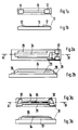
- the two contacts 12 are attached to the ends of the strip 13 so that they each cover the end faces of the strip; in addition, the contacts still adhere to the substrate 11. They consist of an alloy of CrAu or CoFeB and are vapor-deposited or sputtered on.
- the change in the electrical conductivity between the two contacts is the measure of the elongation.
- the conductivity is measured electrically.
- This version is particularly suitable for digital display of the stretch. There is a danger here that two adjacent domains will short-circuit magnetically, and that parts of the domains will rotate from the easy direction, even without stretching.
- the strain gauge (Fig. 2a, 2b) is built up as a double layer.
- the two FeB strips 23, 24 are separated by an SiO2 layer 25 so that the strips are in contact at one end 26.
- the Contacts 22 are each attached to the other end of the strip, as shown in Fig. 2a. It is necessary to change the stripe shape according to Fig. 2a.
- the layers are evaporated or dusted one after the other. This arrangement causes only one domain to be formed in each stripe.
- the easy direction is perpendicular to the longitudinal axis of the strip, the domains of the two strips are antiparallel.
- the elongation is measured via the direct current conductivity as in the exemplary embodiment shown in FIGS. 1a, 1b.
- the measurement signal between elongation and compression still shows a hysteresis.
- the magnetization is superimposed with an external alternating electromagnetic field of frequency ⁇ , the H component of which is perpendicular to the easy direction.
- the magnetization thus oscillates with the frequency ⁇ around the respective rest position, which is determined by stretching.
- the maximum frequency is in the MHz range.
- the electrical conductivity now oscillates, with the frequency ⁇ or 2 ⁇ , or a combination of both frequencies, around a medium conductivity.
- the measured conductivity depends on the rest position of the magnetization and the amplitude of the external alternating field.
- the measure of the elongation is the difference between the maximum and minimum amplitude of the conductivity.
- the corresponding arrangement is shown in Fig. 3a, 3b.
- the amorphous layer 33 is applied as a strip to the substrate 31.
- the easy direction is parallel to the longitudinal axis of the strip.
- the contacts 32 are attached at the ends.
- a strip-shaped layer 35 made of CrAu or Al is located above the insulation layer 34, the direction of which runs parallel to the FeB strip 33.
- the AC voltage applied here provides the alternating magnetic field.
- the stretch to be recorded does not have to be parallel to the longitudinal axis of the strip, it only has to be transmitted via the stretch strip. Since the signal fluctuates periodically, the DC and AC voltage components can be separated electronically and the relevant signal can be further processed as a pure AC voltage signal.
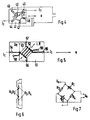
- FIGS. 4, 5 The following two exemplary embodiments (FIGS. 4, 5) are based on the use of the planar Hall effect.
- a circular strain sensor 43 is applied to the substrate 41, with five contacts 44 to 48 abutting the strain sensor.
- the drive current I t flows between the contacts 44 and 45.
- the planar Hall voltage is tapped between the contacts 46 and 47 with 48, the voltage drop along the drive current direction is tapped via the contacts 47 and 48 and can thus be taken into account when determining the Hall voltage.
- the light direction LR runs parallel to the driving current I t .
- the strain can be read off directly as a voltage with a constant driving current I t .
- a superposition of the magnetization with an alternating electromagnetic field is also possible when using the planar effect (FIG. 5).
- the sign of the magnetization is also included in the measurement result, ie there is an AC voltage as the Hall voltage.
- the pure AC voltage signal must first be generated by electronically separating the periodically fluctuating DC voltage signal.
- the Hall voltage oscillates with the frequency of the alternating field ⁇ or with 2 ⁇ or a superposition of both frequencies.
- the measure of the strain is the amplitude of the Hall voltage, which changes in proportion to the strain.
- the strain sensor consists of a Hall probe (Fig. 5); the amorphous layer is vapor-deposited onto a substrate 51 as a square plate 53.
- Four electrical contacts 54 to 57 are attached to the corners.
- the driving current I t flows between the contacts 54 and 55 and the planar Hall voltage is tapped between the contacts 56 and 57.
- the slight direction LR also forms an angle of 45 ° with the direction of expansion and lies in the plane of the leaflet.
- the alternating electromagnetic field is generated in a flat coil 52, the turns of which run parallel to the easy direction.
- the AC electrical voltage is applied to contacts 58 and 59 of coil 52.
- strain transducers R1, R2 are attached to a membrane for pressure measurement.
- the strain transducers R3 and R4 are not subject to stretching, but they serve for temperature compensation when used in a bridge circuit according to FIG. 7.
- U o represents the applied voltage and U s the measurement signal.
- the strain sensor according to the invention does not of course have to consist of an amorphous boron-iron alloy (positive magnetostriction coefficient).
- the amorphous metal of the nickel-iron composition is particularly interesting.
- the magnetostriction coefficient changes its sign at Ni81 Fe19 (atomic percent), which enables further technical designs.
- the amorphous metals show the lowest coercive field strengths, which can be varied by alloying with the metalloids (B, C, Si, Ge, P), zircon or niobium.
- transition metals of the iron group or an alloy consisting of transition metals of the iron group can also be used.
- these show a high coercive field strength and thus a wide hysteresis of the measurement signal.
Landscapes
- Physics & Mathematics (AREA)
- General Physics & Mathematics (AREA)
- Measurement Of Length, Angles, Or The Like Using Electric Or Magnetic Means (AREA)
- Transmission And Conversion Of Sensor Element Output (AREA)
- Fire-Detection Mechanisms (AREA)
- Control Of High-Frequency Heating Circuits (AREA)
- Analysing Materials By The Use Of Radiation (AREA)
Claims (14)
- Capteur extensométrique qui comporte une couche mince (13, 23, 24, 33, 43, 53) constituée d'un matériau ferromagnétique magnétostrictif rapporté sur un substrat ou une membrane et dont la magnétisation varie du fait des propriétés magnétostrictives du matériau par suite d'une variation de longueur, caractérisé en ce que:- la couche mince (13, 23, 24, 33, 43, 53) est anisotrope du point de vue magnétique,- l'anisotropie magnétique présente une orientation préférentielle (L.R.) à laquelle la magnétisation est parallèle à l'état relaxé et qui fait tourner la direction de la magnétisation, lors d'un changement de longueur dans le plan de la couche mince (13, 23, 24, 33, 43, 53), et- et en ce que sont rapportés au moins deux contacts électriques (12, 22, 32, 44, 45, 46, 47, 48, 54, 55, 56, 57) reliés à la couche mince (13, 23, 24, 33, 43, 53), lesquels contacts sont avantageusement disposés sur des faces opposées de la couche mince (13, 23, 24, 33, 43, 53) pour mesurer une valeur de tension qui apparaît du fait de l'effet galvanomagnétique.
- Capteur extensométrique selon la revendication 1, caractérisé en ce que le capteur extensométrique est réalisé en utilisant la magnétorésistance sous forme d'une bande de mesure extensométrique et en ce que l'axe longitudinal de la bande de mesure extensométrique ainsi que l'orientation préférentielle (L.R.) sont dirigés soit parallèlement, soit orthogonalement l'un par rapport à l'autre.
- Capteur extensométrique selon la revendication 2, caractérisé en ce que deux bandes de mesure extensométrique (23, 24) sont empilées l'une sur l'autre et séparées par une couche isolante (25), en ce que les bandes de mesure extensométrique (23, 24) sont reliées en connexion électrique directe à une extrémité de l'empilement (26) et en ce qu'à l'extrémité opposée de l'empilement, un contact électrique (22) est prévu chaque fois sur les bandes de mesure extensométrique (23, 24).
- Capteur extensométrique selon l'une des revendications 1 à 3, caractérisé en ce qu'un conducteur électrique (35), séparé de la bande de mesure extensométrique (33) par une couche isolante (34), est disposé parallèlement à la direction d'orientation magnétique préférentielle, et en ce qu'on applique au conducteur électrique (35) une tension alternative à la fréquence ν où 1 Hz < ν < 1 000 Hz.
- Capteur extensométrique selon la revendication 1, caractérisé en ce que le capteur extensométrique est réalisé en utilisant l'effet Hall dans un plan en guise de couche mince (43, 53) dont la surface présente deux dimensions d'empreinte pratiquement égales, telles que par exemple un cercle ou un carré, et en ce que l'orientation préférentielle (L.R.) et la direction d'extension (σ) font entre elles un angle qui est de préférence de 45°.
- Capteur extensométrique selon l'une des revendications 1, 2, 3 ou 5, caractérisé en ce qu'il est entouré d'une bobine plate dont le bobinage est situé parallèlement à la direction magnétique préférentielle à l'état relaxé et en ce que l'on applique à la bobine une tension alternative à la fréquence ν où 1 Hz < ν < 1 000 Hz.
- Capteur extensométrique selon l'une des revendications 1 à 6, caractérisé en ce que le matériau est un métal de transition du groupe du fer.
- Capteur extensométrique selon l'une des revendications 1 à 7, caractérisé en ce que le matériau est un alliage qui est constitué des métaux de transition du groupe du fer.
- Capteur extensométrique selon l'une des revendications 1 à 8, caractérisé en ce que le matériau est un métal amorphe.
- Capteur extensométrique selon l'une des revendications 1 à 9, caractérisé en ce que le métal amorphe contient un métalloïde (B, C, Si, Ge, P).
- Capteur extensométrique selon l'une des revendications 1 à 10, caractérisé en ce que le métal amorphe contient du zirconium, de l'hafnium et/ou du niobium.
- Capteur extensométrique selon l'une des revendications 1 à 11, caractérisé en ce que le métal amorphe consiste en un alliage: NiXFe(100-x) avec 65 ≦ x ≦ 80 exprimés en pourcentage atomique et 82 ≦ x ≦ 90 exprimés en même pourcentage.
- Capteur extensométrique selon l'une des revendications 1 à 12, caractérisé en ce le métal amorphe consiste en FeZB(100-z) avec la relation 60 ≦ z ≦ 90 en pourcentage atomique.
- Capteur extensométrique selon l'une des revendications 1 à 13, caractérisé en ce que la couche mince présente une épaisseur de 10 à 100 nm.
Priority Applications (1)
| Application Number | Priority Date | Filing Date | Title |
|---|---|---|---|
| AT86100741T ATE74205T1 (de) | 1985-01-23 | 1986-01-21 | Dehnungsaufnehmer. |
Applications Claiming Priority (2)
| Application Number | Priority Date | Filing Date | Title |
|---|---|---|---|
| DE19853502008 DE3502008A1 (de) | 1985-01-23 | 1985-01-23 | Dehnungsaufnehmer |
| DE3502008 | 1985-01-23 |
Publications (3)
| Publication Number | Publication Date |
|---|---|
| EP0189825A2 EP0189825A2 (fr) | 1986-08-06 |
| EP0189825A3 EP0189825A3 (en) | 1989-07-26 |
| EP0189825B1 true EP0189825B1 (fr) | 1992-03-25 |
Family
ID=6260453
Family Applications (1)
| Application Number | Title | Priority Date | Filing Date |
|---|---|---|---|
| EP19860100741 Expired - Lifetime EP0189825B1 (fr) | 1985-01-23 | 1986-01-21 | Capteur extensométrique |
Country Status (7)
| Country | Link |
|---|---|
| US (2) | US4782705A (fr) |
| EP (1) | EP0189825B1 (fr) |
| JP (1) | JPS61181902A (fr) |
| AT (1) | ATE74205T1 (fr) |
| CA (1) | CA1255922A (fr) |
| DE (2) | DE3502008A1 (fr) |
| ES (1) | ES8802344A1 (fr) |
Families Citing this family (50)
| Publication number | Priority date | Publication date | Assignee | Title |
|---|---|---|---|---|
| US4931729A (en) * | 1987-12-22 | 1990-06-05 | Allied-Signal Inc. | Method and apparatus for measuring strain or fatigue |
| US4979395A (en) * | 1987-12-22 | 1990-12-25 | Allied-Signal Inc. | Apparatus and method of forming a magnetic domain strain gage |
| JPH01212301A (ja) * | 1988-02-19 | 1989-08-25 | Toshiba Corp | ひずみセンサ |
| US5136883A (en) * | 1990-08-24 | 1992-08-11 | Jannotta Louis J | Liquid level gage system |
| US5654900A (en) * | 1991-01-10 | 1997-08-05 | Ratner; Leah | Method of and apparatus for optimization of structures |
| SE9102122D0 (sv) * | 1991-07-08 | 1991-07-08 | Skf Nova Ab | Sensor respektive foerfarande foer maetning av vridmoment och/eller krafter |
| DE4203124A1 (de) * | 1992-02-04 | 1992-08-13 | Siemens Ag | Taktiler sensor |
| US5681998A (en) * | 1992-06-09 | 1997-10-28 | Yazaki Corporation | Load measuring device for a vehicle |
| US5631559A (en) * | 1993-03-05 | 1997-05-20 | Northeastern University | Method and apparatus for performing magnetic field measurements using magneto-optic kerr effect sensors |
| US5493220A (en) * | 1993-03-05 | 1996-02-20 | Northeastern University | Magneto-optic Kerr effect stress sensing system |
| DE4408762C2 (de) * | 1993-03-16 | 1999-02-11 | Yazaki Corp | Fahrzeuglastmeßvorrichtung |
| FR2714478B1 (fr) * | 1993-12-23 | 1996-01-26 | Thomson Csf | Détecteur de champ magnétique en couches minces. |
| US5589770A (en) * | 1994-06-27 | 1996-12-31 | Matsushita Electric Industrial Co., Ltd. | Mechanical sensor for detecting stress or distortion with high sensitivity |
| US5505093A (en) * | 1994-11-21 | 1996-04-09 | Brewer Science, Inc. | Homogeneously conductive polymer films as strain gauges |
| US5856617A (en) * | 1997-09-02 | 1999-01-05 | International Business Machines Corporation | Atomic force microscope system with cantilever having unbiased spin valve magnetoresistive strain gauge |
| US6134971A (en) * | 1998-08-27 | 2000-10-24 | University Of Hawaii | Stress induced voltage fluctuation for measuring stress and strain in materials |
| US6579612B1 (en) | 1999-06-24 | 2003-06-17 | International Business Machines Corporation | Magnetostrictive sensor structure |
| US6889555B1 (en) * | 1999-07-20 | 2005-05-10 | Fidelica Microsystems, Inc. | Magnetoresistive semiconductor pressure sensors and fingerprint identification/verification sensors using same |
| US6694822B1 (en) * | 1999-07-20 | 2004-02-24 | Fidelica Microsystems, Inc. | Use of multi-layer thin films as stress sensor |
| DE10023838C2 (de) * | 2000-05-16 | 2002-11-28 | Siemens Ag | Vorrichtung zum Messen einer Wegänderung zwischen Abschnitten eines Bauteils und Verwendung dieser Vorrichtung |
| DE10063535C2 (de) * | 2000-12-20 | 2003-08-14 | Deutsch Zentr Luft & Raumfahrt | Verfahren zur Bestimmung von veränderlichen Zustandsgrößen eines elastischen Systems |
| GB0107182D0 (en) * | 2001-03-22 | 2001-05-09 | Secr Defence | Stress sensor |
| WO2002077528A1 (fr) * | 2001-03-23 | 2002-10-03 | Gvp Gesellschaft Zur Vermarktung Der Porenbrennertechnik Mbh | Procede et dispositif de reglage du rapport air/carburant |
| US6794862B2 (en) * | 2001-05-08 | 2004-09-21 | Ramot At Tel-Aviv University Ltd. | Magnetic thin film sensor based on the extraordinary hall effect |
| US20040164840A1 (en) * | 2003-02-21 | 2004-08-26 | Brown University Research Foundation | Extraordinary hall effect sensors and arrays |
| DE102004032482B4 (de) | 2004-07-05 | 2008-01-31 | Infineon Technologies Ag | Sensor und Verfahren zum Erfassen einer Verformung |
| DE102004032484B3 (de) | 2004-07-05 | 2005-11-24 | Infineon Technologies Ag | Sensor und Verfahren zum Herstellen eines Sensors |
| DE102004034277B4 (de) * | 2004-07-15 | 2009-12-03 | Infineon Technologies Ag | Vorrichtung, insbesondere in einer integrierten Schaltungsanordnung, und Verfahren zur Erfassung eines mechanischen Stresszustands in einem Halbleitersubstrat |
| DE102005005354A1 (de) * | 2005-02-05 | 2006-08-10 | Bosch Rexroth Aktiengesellschaft | Kraftmessvorrichtung und Dehnungsmesselement |
| US8307715B2 (en) * | 2009-03-24 | 2012-11-13 | Direct Measurments, Inc. | Directly applied read and transmit—digital strain encoder and digital load cell |
| JP5680513B2 (ja) * | 2011-09-22 | 2015-03-04 | 住友重機械工業株式会社 | 歪センサの取り付け構造及び歪測定装置 |
| US9394853B2 (en) | 2011-10-12 | 2016-07-19 | Orbital Atk, Inc. | Strain measurement device, a solid rocket motor including same, and related methods |
| US9909860B2 (en) | 2015-04-15 | 2018-03-06 | General Electric Company | Systems and methods for monitoring component deformation |
| US10697760B2 (en) | 2015-04-15 | 2020-06-30 | General Electric Company | Data acquisition devices, systems and method for analyzing strain sensors and monitoring component strain |
| US9557164B2 (en) | 2015-04-15 | 2017-01-31 | General Electric Company | Data acquisition devices, systems and method for analyzing strain sensors and monitoring turbine component strain |
| US9932853B2 (en) | 2015-04-28 | 2018-04-03 | General Electric Company | Assemblies and methods for monitoring turbine component strain |
| US9933321B2 (en) * | 2015-05-14 | 2018-04-03 | Vishay Measurements Group, Inc. | High gage factor strain gage |
| US9846933B2 (en) | 2015-11-16 | 2017-12-19 | General Electric Company | Systems and methods for monitoring components |
| US9953408B2 (en) | 2015-11-16 | 2018-04-24 | General Electric Company | Methods for monitoring components |
| US10012552B2 (en) * | 2015-11-23 | 2018-07-03 | General Electric Company | Systems and methods for monitoring component strain |
| US9967523B2 (en) | 2015-12-16 | 2018-05-08 | General Electric Company | Locating systems and methods for components |
| US9879981B1 (en) | 2016-12-02 | 2018-01-30 | General Electric Company | Systems and methods for evaluating component strain |
| US10132615B2 (en) | 2016-12-20 | 2018-11-20 | General Electric Company | Data acquisition devices, systems and method for analyzing passive strain indicators and monitoring turbine component strain |
| US10126119B2 (en) | 2017-01-17 | 2018-11-13 | General Electric Company | Methods of forming a passive strain indicator on a preexisting component |
| US10872176B2 (en) | 2017-01-23 | 2020-12-22 | General Electric Company | Methods of making and monitoring a component with an integral strain indicator |
| US11313673B2 (en) | 2017-01-24 | 2022-04-26 | General Electric Company | Methods of making a component with an integral strain indicator |
| US10345179B2 (en) | 2017-02-14 | 2019-07-09 | General Electric Company | Passive strain indicator |
| US10502551B2 (en) | 2017-03-06 | 2019-12-10 | General Electric Company | Methods for monitoring components using micro and macro three-dimensional analysis |
| US10451499B2 (en) | 2017-04-06 | 2019-10-22 | General Electric Company | Methods for applying passive strain indicators to components |
| CN108955969B (zh) * | 2018-08-31 | 2021-03-02 | 纳恩博(北京)科技有限公司 | 电阻应变片、感应组件、力传感器和滑板 |
Family Cites Families (20)
| Publication number | Priority date | Publication date | Assignee | Title |
|---|---|---|---|---|
| JPS4218911B1 (fr) * | 1965-04-12 | 1967-07-26 | ||
| US3807223A (en) * | 1972-04-20 | 1974-04-30 | Lignes Telegraph Telephon | Stress sensor with digital output |
| US3943481A (en) * | 1972-06-10 | 1976-03-09 | Denki Onkyo Co., Ltd. | Galvano-magnetic effect device |
| US3774134A (en) * | 1972-12-01 | 1973-11-20 | Honeywell Inc | Antisotropic thin film plated wire magnetostrictive transducer |
| US3858138A (en) * | 1973-03-05 | 1974-12-31 | Rca Corp | Tuneable thin film inductor |
| US3838595A (en) * | 1973-03-16 | 1974-10-01 | Lignes Telegraph Telephon | Data acquisition circuit for a magnetostrictive digital thin film sensor |
| SE376077B (fr) * | 1973-09-13 | 1975-05-05 | Asea Ab | |
| US4138783A (en) * | 1973-10-09 | 1979-02-13 | Soletanche | Method for measuring stresses or forces |
| JPS5442166A (en) * | 1977-09-10 | 1979-04-03 | Toshiba Corp | Pressure transmitter |
| JPS54113379A (en) * | 1978-02-23 | 1979-09-04 | Nec Corp | Pressure gauge |
| EP0033749B2 (fr) * | 1980-02-06 | 1987-11-11 | Hans W. Dipl.-Phys. Keller | Cellule de mesure de la pression piézorésistive en forme de boîte cylindrique |
| JPS56154637A (en) * | 1980-04-30 | 1981-11-30 | Toshiba Corp | Temperature compensating circuit for pressure converter |
| JPS5737233A (en) * | 1980-08-18 | 1982-03-01 | Matsushita Electric Ind Co Ltd | Tension sensor |
| US4374665A (en) * | 1981-10-23 | 1983-02-22 | The United States Of America As Represented By The Secretary Of The Navy | Magnetostrictive devices |
| JPS5884477A (ja) * | 1981-11-13 | 1983-05-20 | Victor Co Of Japan Ltd | プレ−ナ・ホ−ル素子 |
| CA1214660A (fr) * | 1982-09-30 | 1986-12-02 | Koichiro Inomata | Dynamometre, et sa fabrication |
| US4763030A (en) * | 1982-11-01 | 1988-08-09 | The United States Of America As Represented By The Secretary Of The Navy | Magnetomechanical energy conversion |
| JPS59181575A (ja) * | 1983-03-31 | 1984-10-16 | Toshiba Corp | トルクセンサ |
| US4561314A (en) * | 1983-10-27 | 1985-12-31 | General Electric Company | Magnetoelastic force/pressure sensor |
| DE3346643A1 (de) * | 1983-12-23 | 1985-07-04 | Standard Elektrik Lorenz Ag, 7000 Stuttgart | Sensor fuer magnetisierbare materialien |
-
1985
- 1985-01-23 DE DE19853502008 patent/DE3502008A1/de not_active Withdrawn
-
1986
- 1986-01-16 CA CA000499724A patent/CA1255922A/fr not_active Expired
- 1986-01-21 DE DE8686100741T patent/DE3684488D1/de not_active Expired - Lifetime
- 1986-01-21 AT AT86100741T patent/ATE74205T1/de not_active IP Right Cessation
- 1986-01-21 EP EP19860100741 patent/EP0189825B1/fr not_active Expired - Lifetime
- 1986-01-22 JP JP61010324A patent/JPS61181902A/ja active Pending
- 1986-01-23 ES ES551152A patent/ES8802344A1/es not_active Expired
-
1987
- 1987-07-10 US US07/073,355 patent/US4782705A/en not_active Expired - Fee Related
-
1988
- 1988-07-22 US US07/222,799 patent/US4884453A/en not_active Expired - Fee Related
Also Published As
| Publication number | Publication date |
|---|---|
| ES8802344A1 (es) | 1988-05-01 |
| US4884453A (en) | 1989-12-05 |
| EP0189825A3 (en) | 1989-07-26 |
| DE3502008A1 (de) | 1986-07-24 |
| ES551152A0 (es) | 1988-05-01 |
| CA1255922A (fr) | 1989-06-20 |
| US4782705A (en) | 1988-11-08 |
| DE3684488D1 (de) | 1992-04-30 |
| ATE74205T1 (de) | 1992-04-15 |
| EP0189825A2 (fr) | 1986-08-06 |
| JPS61181902A (ja) | 1986-08-14 |
Similar Documents
| Publication | Publication Date | Title |
|---|---|---|
| EP0189825A2 (fr) | Capteur extensométrique | |
| EP0030041B1 (fr) | Transformateur de mesure, notamment d'un champ magnétique généré par un courant de mesure | |
| JP3574186B2 (ja) | 磁気抵抗効果素子 | |
| DE69315665T2 (de) | Ein mechanischer Sensor | |
| DE4427495C2 (de) | Sensoreinrichtung mit einem GMR-Sensorelement | |
| DE10319319A1 (de) | Sensoreinrichtung mit magnetostriktivem Kraftsensor | |
| DE10214946B4 (de) | TMR-Sensor | |
| EP0529959A2 (fr) | Capteur magnétorésistif | |
| US5142227A (en) | Method and apparatus for measuring strain within a ferromagnetic material by sensing change in coercive field | |
| EP0680614A1 (fr) | Dispositif permettant de detecter la position angulaire d'un objet. | |
| WO1994015223A1 (fr) | Detecteur magneto-resistif muni d'une substance antiferromagnetique et son procede de fabrication | |
| DE102009007479A1 (de) | Dünnfilm-Magnetsensor | |
| DE2107076C3 (de) | Magnetischer Schicht-Dickenmesser | |
| DE4232244C2 (de) | Magnetowiderstands-Sensor | |
| DE102011005764A1 (de) | Vorrichtung und Verfahren zum Messen von Magnetfeldern | |
| DE2409323C3 (fr) | ||
| EP0321791A2 (fr) | Jauge extensométrique à domaine magnétique | |
| EP0526044B1 (fr) | Elément à effet de magnéto-résistance | |
| DE69432967T2 (de) | Magnetfeldsonde in Dünnschichtechnik | |
| DE112017003371T5 (de) | Magnetsensor | |
| US5658658A (en) | Magnetoresistance effect elements and method of fabricating the same | |
| EP0460291A2 (fr) | Dispositif sensible au champ magnétique ayant plusieurs détecteurs de champ magnétique | |
| WO2019064994A1 (fr) | Film à couplage d'échange, et élément à effet magnétorésistif ainsi que dispositif de détection d'aimantation l'utilisant | |
| DE102022106912A1 (de) | Magnetsensor | |
| US4212688A (en) | Alloy for magnetoresistive element and method of manufacturing the same |
Legal Events
| Date | Code | Title | Description |
|---|---|---|---|
| PUAI | Public reference made under article 153(3) epc to a published international application that has entered the european phase |
Free format text: ORIGINAL CODE: 0009012 |
|
| AK | Designated contracting states |
Kind code of ref document: A2 Designated state(s): AT CH DE FR GB IT LI SE |
|
| RAP1 | Party data changed (applicant data changed or rights of an application transferred) |
Owner name: STANDARD ELEKTRIK LORENZ AKTIENGESELLSCHAFT Owner name: ALCATEL N.V. |
|
| RAP3 | Party data changed (applicant data changed or rights of an application transferred) |
Owner name: STANDARD ELEKTRIK LORENZ AKTIENGESELLSCHAFT Owner name: ALCATEL N.V. |
|
| PUAL | Search report despatched |
Free format text: ORIGINAL CODE: 0009013 |
|
| RHK1 | Main classification (correction) |
Ipc: G01L 1/12 |
|
| AK | Designated contracting states |
Kind code of ref document: A3 Designated state(s): AT CH DE FR GB IT LI SE |
|
| 17P | Request for examination filed |
Effective date: 19900120 |
|
| 17Q | First examination report despatched |
Effective date: 19900925 |
|
| GRAA | (expected) grant |
Free format text: ORIGINAL CODE: 0009210 |
|
| ITF | It: translation for a ep patent filed | ||
| AK | Designated contracting states |
Kind code of ref document: B1 Designated state(s): AT CH DE FR GB IT LI SE |
|
| REF | Corresponds to: |
Ref document number: 74205 Country of ref document: AT Date of ref document: 19920415 Kind code of ref document: T |
|
| REF | Corresponds to: |
Ref document number: 3684488 Country of ref document: DE Date of ref document: 19920430 |
|
| ET | Fr: translation filed | ||
| GBT | Gb: translation of ep patent filed (gb section 77(6)(a)/1977) | ||
| RAP4 | Party data changed (patent owner data changed or rights of a patent transferred) |
Owner name: ALCATEL SEL AKTIENGESELLSCHAFT Owner name: ALCATEL N.V. |
|
| PLBE | No opposition filed within time limit |
Free format text: ORIGINAL CODE: 0009261 |
|
| STAA | Information on the status of an ep patent application or granted ep patent |
Free format text: STATUS: NO OPPOSITION FILED WITHIN TIME LIMIT |
|
| 26N | No opposition filed | ||
| EAL | Se: european patent in force in sweden |
Ref document number: 86100741.7 |
|
| PGFP | Annual fee paid to national office [announced via postgrant information from national office to epo] |
Ref country code: GB Payment date: 19991213 Year of fee payment: 15 |
|
| PGFP | Annual fee paid to national office [announced via postgrant information from national office to epo] |
Ref country code: DE Payment date: 19991217 Year of fee payment: 15 Ref country code: CH Payment date: 19991217 Year of fee payment: 15 |
|
| PGFP | Annual fee paid to national office [announced via postgrant information from national office to epo] |
Ref country code: SE Payment date: 19991220 Year of fee payment: 15 |
|
| PGFP | Annual fee paid to national office [announced via postgrant information from national office to epo] |
Ref country code: FR Payment date: 19991221 Year of fee payment: 15 Ref country code: AT Payment date: 19991221 Year of fee payment: 15 |
|
| PG25 | Lapsed in a contracting state [announced via postgrant information from national office to epo] |
Ref country code: GB Free format text: LAPSE BECAUSE OF NON-PAYMENT OF DUE FEES Effective date: 20010121 Ref country code: AT Free format text: LAPSE BECAUSE OF NON-PAYMENT OF DUE FEES Effective date: 20010121 |
|
| PG25 | Lapsed in a contracting state [announced via postgrant information from national office to epo] |
Ref country code: SE Free format text: LAPSE BECAUSE OF NON-PAYMENT OF DUE FEES Effective date: 20010122 |
|
| PG25 | Lapsed in a contracting state [announced via postgrant information from national office to epo] |
Ref country code: LI Free format text: LAPSE BECAUSE OF NON-PAYMENT OF DUE FEES Effective date: 20010131 Ref country code: CH Free format text: LAPSE BECAUSE OF NON-PAYMENT OF DUE FEES Effective date: 20010131 |
|
| EUG | Se: european patent has lapsed |
Ref document number: 86100741.7 |
|
| GBPC | Gb: european patent ceased through non-payment of renewal fee |
Effective date: 20010121 |
|
| REG | Reference to a national code |
Ref country code: CH Ref legal event code: PL |
|
| PG25 | Lapsed in a contracting state [announced via postgrant information from national office to epo] |
Ref country code: FR Free format text: LAPSE BECAUSE OF NON-PAYMENT OF DUE FEES Effective date: 20010928 |
|
| PG25 | Lapsed in a contracting state [announced via postgrant information from national office to epo] |
Ref country code: DE Free format text: LAPSE BECAUSE OF NON-PAYMENT OF DUE FEES Effective date: 20011101 |
|
| REG | Reference to a national code |
Ref country code: FR Ref legal event code: ST |
|
| PG25 | Lapsed in a contracting state [announced via postgrant information from national office to epo] |
Ref country code: IT Free format text: LAPSE BECAUSE OF NON-PAYMENT OF DUE FEES;WARNING: LAPSES OF ITALIAN PATENTS WITH EFFECTIVE DATE BEFORE 2007 MAY HAVE OCCURRED AT ANY TIME BEFORE 2007. THE CORRECT EFFECTIVE DATE MAY BE DIFFERENT FROM THE ONE RECORDED. Effective date: 20050121 |