EP0190360B2 - Robot industriel a structure de bras creuse - Google Patents
Robot industriel a structure de bras creuse Download PDFInfo
- Publication number
- EP0190360B2 EP0190360B2 EP85903711A EP85903711A EP0190360B2 EP 0190360 B2 EP0190360 B2 EP 0190360B2 EP 85903711 A EP85903711 A EP 85903711A EP 85903711 A EP85903711 A EP 85903711A EP 0190360 B2 EP0190360 B2 EP 0190360B2
- Authority
- EP
- European Patent Office
- Prior art keywords
- hollow
- tubes
- robot
- outer tube
- transmission gear
- Prior art date
- Legal status (The legal status is an assumption and is not a legal conclusion. Google has not performed a legal analysis and makes no representation as to the accuracy of the status listed.)
- Expired - Lifetime
Links
Images


Classifications
-
- B—PERFORMING OPERATIONS; TRANSPORTING
- B25—HAND TOOLS; PORTABLE POWER-DRIVEN TOOLS; MANIPULATORS
- B25J—MANIPULATORS; CHAMBERS PROVIDED WITH MANIPULATION DEVICES
- B25J9/00—Program-controlled manipulators
- B25J9/02—Program-controlled manipulators characterised by movement of the arms, e.g. cartesian coordinate type
- B25J9/04—Program-controlled manipulators characterised by movement of the arms, e.g. cartesian coordinate type by rotating at least one arm, excluding the head movement itself, e.g. cylindrical coordinate type or polar coordinate type
- B25J9/046—Revolute coordinate type
- B25J9/047—Revolute coordinate type the pivoting axis of the first arm being offset to the vertical axis
-
- B—PERFORMING OPERATIONS; TRANSPORTING
- B25—HAND TOOLS; PORTABLE POWER-DRIVEN TOOLS; MANIPULATORS
- B25J—MANIPULATORS; CHAMBERS PROVIDED WITH MANIPULATION DEVICES
- B25J17/00—Joints
- B25J17/02—Wrist joints
-
- B—PERFORMING OPERATIONS; TRANSPORTING
- B25—HAND TOOLS; PORTABLE POWER-DRIVEN TOOLS; MANIPULATORS
- B25J—MANIPULATORS; CHAMBERS PROVIDED WITH MANIPULATION DEVICES
- B25J18/00—Arms
-
- B—PERFORMING OPERATIONS; TRANSPORTING
- B25—HAND TOOLS; PORTABLE POWER-DRIVEN TOOLS; MANIPULATORS
- B25J—MANIPULATORS; CHAMBERS PROVIDED WITH MANIPULATION DEVICES
- B25J19/00—Accessories fitted to manipulators, e.g. for monitoring, for viewing; Safety devices combined with or specially adapted for use in connection with manipulators
- B25J19/06—Safety devices
- B25J19/063—Safety devices working only upon contact with an outside object
Definitions
- the present invention relates to an industrial robot and, more particularly, to a hollow arm structure for an industrial robot, constructed so that tubes, such as supply tubes for supplying paint and compressed air, or cables, such as a welding cable, can extend through the interior of the hollow arm along the shortest path to a robot work unit, such as a spray gun or a welding head, attached to the forepart of the robot wrist.
- tubes such as supply tubes for supplying paint and compressed air, or cables, such as a welding cable
- the basic construction of the industrial robot comprises a robot body, a swingable upper arm extending upward from the robot body, a lateral forearm pivotally joined to the swingable upper arm, a robot wrist provided on the forepart of the lateral forearm, and a robot work unit attached to the robot wrist.
- the painting robot and the welding robot have a common feature wherein tubes for supplying paint and compressed air and cables for supplying welding electric power are used therein, respectively.
- the tubes and the cables are entwined loosely around the upper arm and forearm thereof in a surplus length.
- the quantity of the tubes and/or cables be reduced to the least necessary extent so that the tubes and/or cables are not wasted uselessly and that the robot work unit, such as a spray gun or a welding head, and its vicinity are cleared of tubes and cables so that unexpected trouble due to the loosening of the tubes and cables is avoided. Accordingly, it is an object of the present invention to provide a hollow arm structure for an industrial robot.
- EP-A-0086054 discloses an industrial robot provided with a hollow arm structure comprising a tubular casing supported on the forepart of a robot upper arm so as to be turnable about an axis perpendicular to the longitucal axis of the robot upper arm; a hollow outer tube rotatably supported at the rear end thereof within the casing so as to project outside from the forepart of the casing; a hollow wrist unit held on the forepart of the hollow outer tube; a plurality of hollow tubes inserted in the hollow outer tube so as to be coaxial with the hollow outer tube and supported rotatably on the hollow outer tube; hollow transmission gears connected to the respective rear ends of the hollow tubes and the hollow outer tube, respectively; gear members rotatably provided within the rear portion of the casing and being in mesh with the hollow transmission gears connected to the respective rear ends of the hollow tubes and the hollow outer tube, respectively; and hollow transmission gear members attached to the respective front ends of the hollow tubes, respectively, to transmit rotative driving force to the wrist unit; and
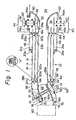
- a hollow arm 10 of the present invention is joined at the rear end to a joint 30 and connected at the front end to a robot work unit 60.
- Rotative driving force is transmitted to the hollow arm 10 through a transmission gear mechanism comprising a coaxial arrangement of an inner bevel gear 32, an intermediate bevel gear 34 and an outer bevel gear 36.
- Predetermined rotative forces are transmitted through a pulley 38 to the inner bevel gear 32, through a pulley 40 to the intermediate bevel gear 34 and through a pulley 42 to the outer bevel gear 36, respectively, from the robot upper arm.
- the joint 30 is provided with a case 44, on which the hollow arm 10 is supported in bearings 46a and 46b by means of a supporting case 48 for turning motion.
- the hollow arm 10 has a hollow inner tube 12, a hollow intermediate tube 14 and a hollow outer tube 16.
- the respective lengths of the inner tube 12, the intermediate tube 14 and the outer tube 16 are selectively and appropriately decided according to a desired arm length.
- These tubes 12, 14 and 16 fit coaxially one within another, namely, the tube 14 within the tube 16, and the tube 12 within the tube 14.
- Bevel gears 18a and 18b are connected to the opposite ends of the inner tube 12 with fastening bolts 20a and 20b, respectively, and the bevel gears are supported rotatably in antifriction bearings 22a and 22b, respectively, and hence the inner tube 12 rotates together with the bevel gears 18a and 18b.
- the fastening bolts 20b are shear bolts.
- the interior of the innertube 12 provides a space for accommodating tubes and/or cables.
- Suitable sealing members such s tetrafluoroethylene O-rings, are provided at the joints between the inner tube 12 and the bevel gears 18a and 18b fastened together with the fastening bolts 20a and 20b, to prevent a leak of the lubricant lubricating the antifriction bearings 22a and 22b into the interior of the inner tube 12.
- the bevel gear 18a is in mesh with a bevel gear 32 provided within the joint 30, and thereby a rotative driving force is transmitted from the bevel gear 32 through the bevel gear 18a and the inner tube 12 to the bevel gear 18b.
- transmission bevel gears 24a and 24b are connected to the opposite ends of the intermediate tube 14 with fastening bolts 26a and 26b and are supported in antifriction bearings 28a and 28b, respectively, and thereby the intermediate tube 14 rotates together with the bevel gears 24a and 24b.
- the bevel gear 24a is in mesh with an intermediate bevel gear 34 provided within the joint 30.
- the fastening bolts 26a, si mi larto the fastening bolts 20b, are shear bolts.
- a bevel gear 21a is connected to one end of the outer tube 16 near the joint 30 with fastening bolts 23a, is in mesh with an outer bevel gear 36 provided within the joint 30 and is supported rotatably in bearings 25a and 25b. Accordingly, a rotative driving force is transmitted from the bevel gear 36 of the joint 30 through the bevel gear 21 a to the outer tube 16 to rotate the outer tube 16 together with the bevel gear 21a.
- the inner tube 12, the intermediate tube 14 and the outer tube 16 forming the hollow arm 10 are driven for rotation by the joint 30 through the transmission mechanism comprising the bevel gears.
- the respective quantities of turning motion of the inner tube 12, the intermediate tube 14 and the outer tube 16 can be regulated by controlling the transmission mechanism.
- the bevel gears 32, 34, 36, 18a, 21 a and 24a are lubricated beforehand with lubricating grease.
- the inner end of the sealing pipe 50 is in sealing contact with the inner circumference of the bevel gear 18a. Since the sealing pipe 50 has the property of a solid lubricant, the inner end of the sealing pipe 50 engages the inner circumference of the bevel gear 18a smoothly for sealing function.
- the hollow arm 10 transmits rotative driving force through the bevel gears 18b and 24b to a hollow wrist unit 56, and then the hollow wrist unit 56 transmits a desired rotation to the robot work unit 60 to control the position of the robot work unit 60 in a three-dimensional space.
- the hollow wrist unit 56 is internally provided with curved sealing pipes 58a, 58b and 58c formed of the same material as that of the sealing pipe 50 to seal the hollow interior of the hollow wrist unit 56 from the lubricating grease lubricating a gear train having bevel gears formed in curved pipes 61 and 63 of the hollow wrist unit 56 and meshing with the bevel gears 18b and 24b of the hollow arm 10, respectively.
- the curved sealing pipes 58a, 58b and 58c form a hollow chamber 66 communicating with the hollow interior of the hollow arm 10 and opening into the robot work unit 60.
- a cover 68 of the hollow wrist unit 56 is connected to the outer tube 16 with bolts.
- the curved sealing pipe 58a is fixed to the cover pipe 68 by suitable means, such as a fixing rib; the curved sealing pipe 58c is fixed to the bevel gear 64 having a curved body by a similar means.
- a bevel gear 62' attached to the front end of the curved pipe 61 is in mesh with a bevel gear 72 provided at the inner end of a wrist flange 70 to transmit rotative driving force to the wrist flange 70.
- This constitution of the hollow arm 10 enables the utilization of the hollow interior of the hollow arm 10 as a space for wiring and piping.
- a paint supply tube and a compressed air supply tube are inserted through the opening 54 of the sealing pipe 50, and then the same are extended through the hollow interior of the hollow arm 10 and further through the hollow chamber 66 of the hollow wrist 56 and an opening formed in the wrist flange 70 to the robot work unit, namely, a spray gun, to supply paint and compressed air to the spray gun.
- the wrist unit 56 and the robot work unit 60 are driven for rotary motion according to the rotary motion of the outer tube 16 and the cover 68 of the forearm, the rotary motion of the intermediate tube 14 and the curved pipe 63, and the rotary motion of the thinnest inner tube 12, the curved pipe 61 and the wrist flange 70.
- the excessive load is transmitted through the curved pipe 63 and the bevel gear 64 attached to the rear end of the curved pipe 63 to the bevel gear 24b attached to the front end of the intermediate tube 14, and also through the wrist flange 70, the curved pipe 61 and a bevel gear 62 attached to the rear end of the curved pipe 61 to the bevel gear 18b attached to the front end of the thinnest inner tube 12.
- the inner tubes 12 and 14 and the bevel gears 18b and 24b are fastened together with the shear bolts 20b and 26b, respectively.
- Figure 2 illustrates an industrial robot employing the hollow arm 10 as a robot forearm, in which the hollow arm 10 is joined pivotally to the joint 30 of a robot upper arm 80, while the robot upper arm 80 is joined pivotally to a robot body 90.
- a robot work unit 60 such as a spray gun or a welding head, is attached to the wrist unit 56.
- the present invention provides an industrial robot extremely well protected from damage.
Landscapes
- Engineering & Computer Science (AREA)
- Robotics (AREA)
- Mechanical Engineering (AREA)
- Manipulator (AREA)
Abstract
Claims (1)
Applications Claiming Priority (5)
| Application Number | Priority Date | Filing Date | Title |
|---|---|---|---|
| JP15517784A JPS6133887A (ja) | 1984-07-27 | 1984-07-27 | 工業用ロボツトの中空腕構造 |
| JP155177/84 | 1984-07-27 | ||
| JP157294/84 | 1984-07-30 | ||
| JP15729484A JPS6138891A (ja) | 1984-07-30 | 1984-07-30 | 中空腕形工業用ロボツト |
| PCT/JP1985/000424 WO1986000846A1 (fr) | 1984-07-27 | 1985-07-26 | Robot industriel a structure de bras creuse |
Publications (4)
| Publication Number | Publication Date |
|---|---|
| EP0190360A1 EP0190360A1 (fr) | 1986-08-13 |
| EP0190360A4 EP0190360A4 (fr) | 1987-11-25 |
| EP0190360B1 EP0190360B1 (fr) | 1991-01-23 |
| EP0190360B2 true EP0190360B2 (fr) | 1994-06-15 |
Family
ID=26483245
Family Applications (1)
| Application Number | Title | Priority Date | Filing Date |
|---|---|---|---|
| EP85903711A Expired - Lifetime EP0190360B2 (fr) | 1984-07-27 | 1985-07-26 | Robot industriel a structure de bras creuse |
Country Status (3)
| Country | Link |
|---|---|
| EP (1) | EP0190360B2 (fr) |
| DE (1) | DE3581531D1 (fr) |
| WO (1) | WO1986000846A1 (fr) |
Families Citing this family (1)
| Publication number | Priority date | Publication date | Assignee | Title |
|---|---|---|---|---|
| IT1211558B (it) * | 1987-11-26 | 1989-11-03 | Bruno Bisiach | Robot a fascio laser per taglio e saldatura |
Family Cites Families (15)
| Publication number | Priority date | Publication date | Assignee | Title |
|---|---|---|---|---|
| JPS4844948Y1 (fr) * | 1969-08-18 | 1973-12-24 | ||
| JPS4937140B1 (fr) * | 1970-11-09 | 1974-10-05 | ||
| JPS5028711B1 (fr) * | 1970-11-16 | 1975-09-17 | ||
| JPS49124766A (fr) * | 1973-03-31 | 1974-11-29 | ||
| JPS5339666B2 (fr) * | 1973-07-20 | 1978-10-23 | ||
| JPS5841996B2 (ja) * | 1976-02-27 | 1983-09-16 | 株式会社椿本チエイン | 工業用ロボツトの手首機構 |
| JPS5847318B2 (ja) * | 1976-11-01 | 1983-10-21 | 川崎重工業株式会社 | 塗装用ロボットの手首 |
| US4068536A (en) * | 1976-12-23 | 1978-01-17 | Cincinnati Milacron Inc. | Manipulator |
| JPS5435959A (en) * | 1977-08-25 | 1979-03-16 | Toshiba Corp | Safety device of industrial robot |
| JPS571693A (en) * | 1980-06-03 | 1982-01-06 | Matsushita Electric Industrial Co Ltd | Safety device for wrist section of industrial robot |
| US4365928A (en) * | 1981-05-04 | 1982-12-28 | Cincinnati Milacron Inc. | Fluid power connector system for manipulator |
| US4636138A (en) * | 1982-02-05 | 1987-01-13 | American Robot Corporation | Industrial robot |
| DE3370299D1 (en) * | 1982-11-02 | 1987-04-23 | Westinghouse Electric Corp | Robot wrist and arm |
| DE3244019C2 (de) * | 1982-11-27 | 1985-10-24 | Jungheinrich Unternehmensverwaltung Kg, 2000 Hamburg | Industrie-Roboter |
| JPS609694A (ja) * | 1983-06-30 | 1985-01-18 | フアナツク株式会社 | 工業用ロボツトの安全継手 |
-
1985
- 1985-07-26 DE DE8585903711T patent/DE3581531D1/de not_active Expired - Lifetime
- 1985-07-26 EP EP85903711A patent/EP0190360B2/fr not_active Expired - Lifetime
- 1985-07-26 WO PCT/JP1985/000424 patent/WO1986000846A1/fr not_active Ceased
Also Published As
| Publication number | Publication date |
|---|---|
| WO1986000846A1 (fr) | 1986-02-13 |
| EP0190360B1 (fr) | 1991-01-23 |
| EP0190360A1 (fr) | 1986-08-13 |
| EP0190360A4 (fr) | 1987-11-25 |
| DE3581531D1 (de) | 1991-02-28 |
Similar Documents
| Publication | Publication Date | Title |
|---|---|---|
| US8347753B2 (en) | Industrial robot with tubular member for a cable harness | |
| EP1970171B1 (fr) | Poignet de robot articulé | |
| KR100711314B1 (ko) | 다관절 매니퓰레이터 | |
| EP0756918B1 (fr) | Dispositif de poignet pour robots industriels | |
| EP0279591B1 (fr) | Manipulateur robotisé | |
| EP0080325B1 (fr) | Poignet à rotule pour robot de manipulation | |
| EP0593786B1 (fr) | Systeme permettant la manipulation de cables pour bras de robot industriel | |
| EP1625920A1 (fr) | Structure de guidage pour un câble ombilical d'un robot industriel | |
| EP0314839A1 (fr) | Dispositif de positionnement | |
| JP2000511828A (ja) | ロボットアームにおけるデバイス | |
| US5498163A (en) | Fluid/electrical rotary joint | |
| CA2078937C (fr) | Mecanisme de poignet de robot industriel | |
| JPH05237790A (ja) | 危険な場所で使用するための電気ロボット | |
| CN101200068A (zh) | 机器人手腕 | |
| EP0621112A1 (fr) | Robot industriel ayant des joints articules utilisant un engrenage reducteur creux | |
| NZ332251A (en) | Welding robot utilising gas shielded welding with power cable connected to welding electrode within a welding nozzle via slip ring assembly | |
| EP0190360B2 (fr) | Robot industriel a structure de bras creuse | |
| WO1985002576A1 (fr) | Mecanisme d'entrainement du poignet d'un robot industriel | |
| JP3512679B2 (ja) | 産業用ロボットの手首装置 | |
| US4773813A (en) | Industrial robot | |
| JP4559419B2 (ja) | ロボットの手首 | |
| EP0187871B1 (fr) | Robot industriel a structure de bras variable | |
| JPS6133887A (ja) | 工業用ロボツトの中空腕構造 | |
| JP2005297069A (ja) | アーク溶接ロボットにおける溶接ワイヤの供給機構 | |
| KR100380815B1 (ko) | 수직 다관절 로봇 |
Legal Events
| Date | Code | Title | Description |
|---|---|---|---|
| PUAI | Public reference made under article 153(3) epc to a published international application that has entered the european phase |
Free format text: ORIGINAL CODE: 0009012 |
|
| 17P | Request for examination filed |
Effective date: 19860418 |
|
| AK | Designated contracting states |
Kind code of ref document: A1 Designated state(s): DE GB |
|
| A4 | Supplementary search report drawn up and despatched |
Effective date: 19871125 |
|
| 17Q | First examination report despatched |
Effective date: 19890530 |
|
| GRAA | (expected) grant |
Free format text: ORIGINAL CODE: 0009210 |
|
| AK | Designated contracting states |
Kind code of ref document: B1 Designated state(s): DE GB |
|
| REF | Corresponds to: |
Ref document number: 3581531 Country of ref document: DE Date of ref document: 19910228 |
|
| PLBI | Opposition filed |
Free format text: ORIGINAL CODE: 0009260 |
|
| 26 | Opposition filed |
Opponent name: ASEA BROWN BOVERI AB Effective date: 19911016 |
|
| PGFP | Annual fee paid to national office [announced via postgrant information from national office to epo] |
Ref country code: GB Payment date: 19930716 Year of fee payment: 9 |
|
| PGFP | Annual fee paid to national office [announced via postgrant information from national office to epo] |
Ref country code: DE Payment date: 19930726 Year of fee payment: 9 |
|
| PUAH | Patent maintained in amended form |
Free format text: ORIGINAL CODE: 0009272 |
|
| STAA | Information on the status of an ep patent application or granted ep patent |
Free format text: STATUS: PATENT MAINTAINED AS AMENDED |
|
| 27A | Patent maintained in amended form |
Effective date: 19940615 |
|
| AK | Designated contracting states |
Kind code of ref document: B2 Designated state(s): DE GB |
|
| PG25 | Lapsed in a contracting state [announced via postgrant information from national office to epo] |
Ref country code: GB Effective date: 19940726 |
|
| GBPC | Gb: european patent ceased through non-payment of renewal fee |
Effective date: 19940726 |
|
| PG25 | Lapsed in a contracting state [announced via postgrant information from national office to epo] |
Ref country code: DE Effective date: 19950401 |