EP0190399A2 - Elektronisches Fernsteuer- und Fernmesssystem - Google Patents
Elektronisches Fernsteuer- und Fernmesssystem Download PDFInfo
- Publication number
- EP0190399A2 EP0190399A2 EP85112781A EP85112781A EP0190399A2 EP 0190399 A2 EP0190399 A2 EP 0190399A2 EP 85112781 A EP85112781 A EP 85112781A EP 85112781 A EP85112781 A EP 85112781A EP 0190399 A2 EP0190399 A2 EP 0190399A2
- Authority
- EP
- European Patent Office
- Prior art keywords
- information
- station
- central station
- remote
- block
- Prior art date
- Legal status (The legal status is an assumption and is not a legal conclusion. Google has not performed a legal analysis and makes no representation as to the accuracy of the status listed.)
- Withdrawn
Links
Images


Classifications
-
- G—PHYSICS
- G08—SIGNALLING
- G08C—TRANSMISSION SYSTEMS FOR MEASURED VALUES, CONTROL OR SIMILAR SIGNALS
- G08C17/00—Arrangements for transmitting signals characterised by the use of a wireless electrical link
- G08C17/02—Arrangements for transmitting signals characterised by the use of a wireless electrical link using a radio link
-
- G—PHYSICS
- G06—COMPUTING OR CALCULATING; COUNTING
- G06F—ELECTRIC DIGITAL DATA PROCESSING
- G06F2219/00—Indexing scheme relating to application aspects of data processing equipment or methods
- G06F2219/10—Environmental application, e.g. waste reduction, pollution control, compliance with environmental legislation
Definitions
- the present invention relates to an electronic remote control and telemetry system, specially applicable in forecasting and controlling pollution agents.
- a series of data and values relative to a diversity of parameters and functions existing at points sufficiently distant from a central station can be obtained therein, the information being transmitted automatically over a radio which prints-out a transmission priority protocol at the various connecting points or remote stations to the central station.
- the system of the invention is comprised of a central station equipped with all the necessary elements to communicate with an assembly of terminals or remote stations depending functionally from the said central station.
- a communications network completely hierarchized by the central station, is formed which will cyclically make selective calls over a shared communication channel.
- a preferred embodiment of this invention resides in collecting the metereological and contamination data existing in surrounding points, at different distances from the power producing plant, so that the degrees of contamination generated by said plant are known at all times in order to make the necessary corrections in the functioning thereof and to avoid or lessen the degrees of contamination as far as possible.
- the system in its preferred embodiment, is based on the configuration of a radiometry network of the atmospheric phenomena produced by a power plant both in its nearby surroundings and in a radius close thereto, which can present a variable amplitude.
- the system is comprised of a determined number of collection stations capable of preparing information relative to the degree of contamination of the atmosphere at this point, radio-transmitting said information to a central station well equipped with a data processing unit as well as a mimic panel which will alert the central operator as to the different variable circumstances occurring in the surroundings of the said central.
- the said collection stations will transmit, as indicated, by radio, analog and ditigal information concerning the existing contaminating parameters, as well as any other information of interest.
- the central station of the system is controlled by a basic processor communicated with an auxiliary processor whose main tasks are the permanent scanning of the communication channels, the communication itself with the auxiliary processor, the maintenance of the communications, the monitoring of the operator's controls typed therein, as well as the assitance of a visual display element and the monitoring of the "watch dog" device.
- the task of the auxiliary processor is to collect the information transmitted thereto by the said basic processor in a protocolized manner, preparing such information to be recorded by a printer included in the system.
- this auxiliary processor is assigned the tasks of implanting and reading the time of day clock of the system maintained by an alkaline battery.
- the information channels are connected to the system via a series of cards having different tasks.
- the system includes analog signal input cards, analog signal output cards, digital signal input cards, digital sign a l output cards and communications protocol cards.
- the central station incorporates a group of modems for transmitting information over telephone lines.
- each remote station is such that it permits the obtainment of a series of data and parameters relative to its environment, as well as to its intrinsic operative conditions for radio-transmitting them to the central station, once this has transmitted the information request signal.
- Each of these remote stations comprises a processor assisted by a program and operating memory block.
- These stations also include a UART block (universal asynchronous receiver-transmitter) connected to a modem unit (modulator-demolulator) which communicates with the radio station.
- This assembly forms a communication channel permitting the radio to be linked with the central station according to network discipline established in the central station itself.
- the remote stations have the characteristic of presenting a fixed array of channels, not programmable by the user, differing from that occurring in the central stations.
- the remote stations also include a display/ selector which optically displays the input/output states, depending on the value of a pre-selector, permitting a functional verification to be made and the position of the STATE word, indicative of the phase of the internal operations and of the communications, to be known.
- the remote stations are further provided with a series of channel cards to permit analog and digital signals to be processed both at the input to the remote station and at the output or transmission thereof to the central station.
- the electronic structure of these stations incorporates a "watch dog" device consisting of a monitor block permitting the equipments to be re-started if the functional cycle of the processor has been lost or if the power in the station has been lost.
- the data to be transmitted are logically obtained through suitable sensors and transducers, the type of which will logically depend upon the parameter and variable to be controlled.
- a radial network for transmitting data is consolidated, whereby the situations existing in the area surrounding the central station can be ascertained in a centralized manner.
- the power plant operator could adopt the necessary measures, such as regarding the type of fuel to be burnt in the plant, to maintain the ambient contamination below the maximum levels permitted by the administration.
- the system can be completed by connecting a plurality of power plants, via a communication line, to a centralized post where, apart from controlling and counting the information received by each of the power plants from their remote collection stations, a propagation pattern of the contaminating agents can be prepared and evaluated, whereby the immissions to be produced within the next few hours can be forecasted, depending upon a metereological chart as well as on patterns proportioned by a series of program application packets. All this would configure a radial data exchange network relative to the atmospheric contamination which
- the local network of the system that is the assembly formed of a signal receiving station, nearby a power producing plant, and a plurality of remote contaminating data collection stations, is a local network divided into three different parts, viz:
- the transmission assembly will be formed of a radio network, preferably in the VHF band, having a radial configuration, so that all the remote stations of the system operate at the same frequencies.
- the radio network of all the stations will be comprised of duplex mono-channel equipment. Due to the selection of operating at the same frequency, a sequencial discipline must be maintained in the communication between the remote stations and the central station, which communication will be controlled by two telemetry systems.
- the central station will transmit a carrier signal continually, cyclically searching the remote stations.
- the searched station will then transmit the carrier signal and will, after the necessary delay, transmit its state information.
- the radio equipments used in the system are ready for interconnection with a modem of about 200 bauds and are provided with the necessary emission control devices for connection to the telemetry system.
- the task of the telemetry system is to transmit the analog and digital signals, generated in each of the remote stations, to the central station.
- the remote stations check the input information, preparing a signal or telegram to be transmitted.
- each remote station will periodically search each remote station which transmits a reply message indicative of the changes in the controlled parameters detected at the input of the station.
- each remote station is provided with a series of analog and digital inputs through which the electric signals, equivalent or proportional to the parameters controlled by each of the remote stations, are introduced in the telemetry system.
- the system must include a central station capable of controlling at least 20 remote stations, and operating with a maximum 2-minute cycle time, although all these numbers and parameters can be varied, depending upon the requirements of each case.
- the display assembly will preferably be fixed to the central itself or close thereto, and will be comprised of a microcomputer capable of processing information received through the telemetry system, and also controlling a mimic panel and a printer, through which the operator will obtain, in a written form, the data proportioned by the system.
- the mimic panel will offer a visual display of these same parameters and can activate alarms so that the power plant personnel can modify the operative conditions thereof, always maintaining the plant in an optimum functioning condition in view of the pollution generated.
- the system includes the possibility of centralizing at a single data processing point all the information received from the various power plants, so that with the program application packet support, the data from the various local stations of each of the power plants can be 'collected, and the data received can be evaluated and correlated, effecting various preparatory steps, such as contamination forecasts, depending upon the prevailing atmospheric chart, actuation of the power plant, depending on the forecasts made, and subsequent comparison between the results obtained and the prior forecasts.
- various preparatory steps such as contamination forecasts, depending upon the prevailing atmospheric chart, actuation of the power plant, depending on the forecasts made, and subsequent comparison between the results obtained and the prior forecasts.
- Stadistical analysis, data banks, etc. can also be performed.
- the electronic remote control and telemetry system of the invenion is comprised of a central station equipped with the elements so that it can be radio-connected to an assembly of terminals or remote stations depending hierarchically from this central station.
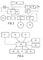
- FIG. 1 The block diagram of figure 1, showing the functional arrangement of the central station, illustrates that it is comprised of a main processor 1 connected to a data and command inserting keyboard and to visual display means, which are generally designated by the block 2.
- the main processor l electrically fed by the power supply 3 which includes the battery 4, is monitored by the "watch dog" device 5.
- the keyboard included in the block 2 permits the keyboard pulses to enter the processor, while the processor transmits the pertinent information displayed on the visual display means.
- the processor 1 is also assisted by the auxiliary processor 6 which collects the information transmitted thereto by the main processor in a protocolized manner, and prepares it for recordal by a printer 7.
- the task of the auxiliary processor 6 is to implant and read the time of day clock 8 which is electrically maintained by an alkaline battery.
- the processor-1 also controls the channel cards included in the block 9 and the communication card 10.
- the channel card 6 handles the block 11 through which the measures adopted by the system are inserted, while the pertinent commands are transmitted via the block 12 to the remote stations.
- the communication card 10 handles the modems 13 and 14, respectively.
- Block 17 consists of a DART block (universal asynchronous receiver-transmitter) which is used, along with the modem 18, to communicate with a radio station, according to the established network discipline of the system.
- DART block universal asynchronous receiver-transmitter
- Block 19 consisting of a display/selector also depends on the processor 15 and displays the input/ output states depending upon the value of a pre-selector, thereby allowing a minimum functional verification of the equipment as well as an'access to the processor state word, which will indicate the phase of the internal-operations and the communications.
- a watch dog device 20 is also included, which consists of a monitor for restarting the equipment if the functional cycle of the processor is lost or if any of the internal supplies of the equipment is lost.
- the processor 15 controls the blocks 21, 22 and 23 which, respectively, control the analog signal inputs, the digital signal input block, and the digital signal output block.
- the analog input card 21 receives the signals from the measuring channels 24 through which the value of the variable to be controlled by the system is detected. In this block 21 the said measuring channels 24 undergo the analog-digital transformation.
- the transformed information is conveyed to corresponding physical magnitudes, in the central station once radio-transmitted, and taking into account the functions assigned to each of the remote stations, depending on how the preparation thereof has been configured.
- the digital input block 22 is capable of collecting, in a preferred embodiment, up to 24 input signals, conveying the information to the processor.
- This block 22 receives the signals from various contact channels 25 represented in the diagram of figure 3.
- the digital outputs, handled by block 23, have two different tasks, viz:
- the telemetry system for forecastle and controlling polluting agents is comprised of a plurality of remote stations, referenced respectively l a ... l n communicating with a radio emitting-receiving block 2a ⁇ 2 n provided in the remote stations and which, preferably, operate in the monochannelled VHF band.
- These blocks 2 a ?? 2 n communicate logically by radio with a single emitting-receiving master station 3 in a centralized station 28 close to a power producing plant or any other industry generating, from an ecological point of view, contaminating agents.
- the information collected by the radio station 29 is received via a modem in this centralized station 28, transmitting this information via the corresponding modem included in the generic block 30, to the control unit 31 including the modem 32 which processes the received signals to transmit them to a processing computer 33 which is as- isted by the graphic console 34, the disk unit 35, the printer 36 and the plotter 37.
- the radio communication system between the central station 28 and the remote stations l a Vietnamese n will take place, the central station 28 continually transmitting a carrier wave.
- the reception/transimission switching will take place by means of the telemetry system, these remote stations transmitting a carrier signal only during the transmission of the reply message to the central station, although in principle, information is only transmitted by including a low- speed modem.
- the system can further be completed by transmitting spoken information, which could be of interest when adjusting the various parts of the system, or in determined emergency situations.
- the central station 28 is completed by the-signals transmitted thereto by an optional metereological station 38 represented in the diagram of figure 2.
- the control unit collects the analog and digital information from all the remote stations and that supplied thereto by the central station 28, duly processing the information according to the control program.
- control unit 31 will attend to three different types of signals:
- the received a) type signals will be entered at determined periods of tine, obtaining different average values during time intervals and analyzing the results obtained, according to the established program.
- Statistic operations will also be performed under the control of the program included in the microcomputer 33.
- peripheral devices 34, 35, 36 and 37 By means of the peripheral devices 34, 35, 36 and 37, the user will dispose of the input/output means to control the system and he will become aware at all times of the different situations occurring in the area controlled by the remote stations.
- the intrinsic structure of the central station 28 is illustrated in the block diagram of figure 1, which has already been described.
- the processor 15 through its asynchronous transmitter 17, communicates with the modem 18 controlling the 2- or 4-wired transmission line 39.
- the radio actuator 29 is commanded from the said digital output block 23.
- the remote station is capable of radio-transmitting to the central station the different state data, when so requested by the central station itself.
- a series of informations relative to the contamination existing in a determined area preferably that surrounding a power producing plant, can be compiled.
- this information can be conveyed through written documents, through the opportune printer, apart from activating various types of optical and/or aural alarms, so that the central personnel or that of contaminating industries may make the necessary rectifications to lessen the degree of ambient contamination.
- the system includes a series of real time programs and parameter evaluation and correlation programs which, duly applied to an information evaluation computer, will increase the performance of the system.
- figure 4 represents the breaking down, by blocks, of the process in real time.
- the block 40 for collecing data from the stations permits values to be collected from metereological stations, offering the immission values of the remote stations, and detecting, classifying and alerting as to the communication problems of the general network of the system.
- the analysis and control blocks 48 interactively scan the values introduced through the operator's console.
- the operator commands 42 permit him to have access to the information stored in the system, by recognizing a series of commands to which he has access. Besides, it offers information concerning the most significant events, of interest to the.system personnel.
- the results displayed on the screen 43 alert of spontaneous alarms which can occur at any time, and presents the variation of the parameters selected by the station or by the service (Metereologic, areas, spatial distributions, etc.).
- the process block 44 results on a printer, facilitates summaries of the metereological values conveniently divided into times. Summaries of the emission tata classified by stations are also available.
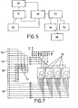
- the analysis and control block 48 is provided with a performance routine which is summarised in the block diagram of figure 5.
- the system analyses the deviations existing between the foreseeable results and those really obtained in the metereological stations,according to the Metereological Institute forecasts. These results facilitate the creation and up-dating of a data base for the predictable behaviour of the possible degrees of contamination existing in a determined area.
- the prior data is studied and compared with the emission data obtained by telemetry in each of the collection stations, more accurate aerial forecasts are made, and the results are displayed on a graphic screen as well as on a plotter.
- the system of this invention having a special embodiment, facilitates an improvement in the pollution conditions of the atmosphere or ecological environment surrounding a power plant or contaminating industry, complying with the official regulations. It is also possible, with the special embodiment. of the invention, to prepare and evaluate a propagation pattern of the contaminating agents which permit the immissions that can be produced within the next few hours, depending upon a determined metereological chart, to be forecasted.
- circuit arrangement of figure 6 of the drawings represents the card included in the processor 1. This circuit presents the section of the processor itself, the address demultiplexer and the wait cycle generator.
- the microcomputer 49 such as Intel's 8085 A, has been selected.
- This microcomputer operates with the quartz crystal 50 having a typical frequency of 6144 KHz, proportioning the central process unit with a cycle time of 325 nanoseconds.
- This wait cycle can be generated via the intergrated circuit 51.
- the Data bus connects the various peripheral devices to the microprocessor.
- the eight address elements which are lighter in weight are demultiplexed from this data bus via the integrated circuit 52, with the intervention of the ALE command (pin No. 30 of the integrated circuit of the microprocessor 49).
- the demultiplexed address bus will be obtained comprising sixteen bits, which will permit the addressing of 64 K memory positions.
- the memory block of this processor section of the central station is divided into 8 Kbyte modules, the card being provided with 7 frames having 28 connections, which will permit the installation of
- a live CMOS type memory could also be installed at this position, which will be fed from a certain supply from a small alkaline battery resident in the power supply, permitting the data to be maintained in conditions of off system.
- live CMOS type memories are installed, having a capacity of 2 Kbytes per position.
- This processor card includes a time base generating phase for serving the real time interruption system, apart from permitting the generation of the telegraphic frequency of the serial channel used in the system.
- the clock output signal (CLK OUT) having a frequency of 3,072 KHz is obtained from the format 37 of the microprocessor 49, which frequency is divided into a chain formed of a biquinary counter 60 and a binary divider 61 with a division factor of 2 12 . Due to this structure and depending upon bridges 62 made, frequencies of 38.400 Hz, 19,200 Hz, 9,600 Hz, 4,800 Hz, 1,200 Hz and 300 Hz can be obtained, which Mill serve as a basis for obtaining the transmission rates of, respectively, 2,400 bauds, 1,200 Bd, 600 Bd, 300 Bd, 75 Bd and for clock rates of 3.3 milliseconds.
- frequencies of 3,072KHz, 614,4 KHz and 307,2 KHz can also be generated for their use in the bus of the system.
- the said 3.3 millisecond signal will be utilised for the real-time interruption system.
- the circuits 64 and 65 act as address decodifiers.
- the former acts as an 8 Kbyte segment decodifier, while the circuit 65 generates four addresses in the last 8 Kbyte segment, which are assigned to a keyboard controller circuit 66 (such as Intel's 8,279), to a serial channel, for controlling the bus of the system (decodifier 46), and to an external auxiliary channel via circuit 67 whereby the entry of the external data to the card of the processor is controlled.
- a keyboard controller circuit 66 such as Intel's 8,279
- serial channel for controlling the bus of the system (decodifier 46)
- an external auxiliary channel via circuit 67 whereby the entry of the external data to the card of the processor is controlled.
- the keyboard controller and the visual display means 66 is a "suspended" integrated circuit of the data bus and permits the entry of the keyboard pulses duly codified and the refreshment of the visual display means (block designated by 2 in figure 1).
- the circuit 68 deco- difies the scanning.
- the integrated circuit 69 comprises a 20 milliamp looped serial communications channel, permitting the asynchronous signalling of the information.
- the circuits 70 and the opto couplers 71 permit the signal to be adapted so that a current insulated loop based on the auxiliary input voltage is obtained.
- the opto couplers 72 insulate the processor galvanically and the processor could generate, through these opto couplers, alarm information and could also enter an external acceptance signal thereof.
- FIG. 7 The block designated by 2 in figure 1, corresponding to the keyboard and the visual display means, is schematically illustrated in figure 7 of the drawings.
- Reference numeral 73 thereof corresponds to sixteen keys or buttons forming the keyboard itself. Eleven of these keys must form a numeric keyboard whilst the remaining five keys determine a functional keyboard.
- Pressing of any one of these keys is detected through the scanning effected by the card of the processor (figure 6).
- the lines 74 enter the scanning while the eight lines 75 transmit the return information, detecting the pressing of any key.
- the display 76 as illustrated in figure 7, is formed of four digits which are monitored by lines 77, while lines 78 select the segments of each of the digits of the display 76.
- This figure 8 illustrates the presence of a microprocessor 79 which assigns this section of the system a totally autonomous nature.
- This microprocessor shall preferably be of the 8,748 type and consolidates the auxiliary processor of the central station. It has the following tasks:
- the clock signal can also be collected from the outside of this plate by acting, in this case, as the oscillator and the separator of the circuits 92 and 93.
- the processor 79 communicates with the main processor 1, through the double port formed by the circuits 94, 95 and 96.
- all the control circuits of the electrode of the printer are galvanically insulated to prevent the protective ground noise from being injected into the mass of the processor, taking into account that the metalized printing paper is in contact with the protective ground and, therefore, constitutes an electrode during programming.
- Block 9 of figure 1 includes an analog channel card, the circuitry arrangement of which is shown in figure 9.
- This analog channel card is capable of entering sixteen referenced analog signals, multiplexing this information via the circuits 97, 98 and 99, subjecting the signal to an instrumental amplifier formed of the circuits 100, 101 and 102, and then digitalizing the value by an analog-digital converter 103, preferably of the type utilising the method of registering by successive approximations.
- the reference resistor step of this circuit 103 is fed by a pattern signal obtained from the circuit 104 and stablised by a forced heating system incorporated into the circuit.
- This card permits the coupling of a conversion table, via the circuit 105 which can contain sixteen 1/4 Kbyte pages, facilitating an independent lineation for each of the sixteen measuring channels. In the event this process were not necessary, this circuit 105 will be replaced by a bridge assembly.
- the integrated circuit 16 makes an-appropriate division of the clock fequency of the bus of the system so that the clock signal required by the analog-digital converter 103 can be obtained.
- Digital signals enter the central station via the circuit shown in figure 10.
- This circuit includes cuit _includes sixteen reference input signal points 1071, 107 2 ?? 107 16 and a common nodal point 108. These inputs act on corresponding optocoupling phases 109 1 , 109 2 ... 109 16 , each of which is so connected that the input signal can have a positive, negative or alternate sine wave polarity, due to the presence of two anti-parallel optocouplers in each of the optocoupling phases 109 i .
- two optocoupling sections can be observed in each of the digital signal input phases, as well as a transistor 101 i , and dependent components act- i n g on the output signal of these circuits 109 i .
- the signals obtained from this galvanic barrier are treated by logic gates 111, 112 and 113 which are controlled by a preselector formed of the circuits 114 and 115 transmitting the information to the bus of the system via the assembly of lines 116.
- the digital output signal from the central to other pheripheral devices or remote stations are handled by the circuitry shown in figure 11.
- This digital output card contains sixteen operating channels. Eight of these sixteen channels, designated by 117 1 , 117 2 ... 117 8 , can be installed internally in a relay to obtain free potential contacts. The remaining eight channels designated by 118 1 , 118 2 .... 118 8 , constitute open flip-flop outputs for controlling possible external relays.
- the circuits 119, 120, 121 and 122 consist of D-type flip-flops which are activated at the upward side of the clock signal.
- Each data is handled in two cycles: a first written cycle in which the information, along with a new additional information indicative of to which of the four prior circuits (119 to 122) it corresponds. After performing this operation, the information is stored in the circuits 123 or 124. A second reading cycle in which the information is placed in the corresponding storage circuit, being retained therein definitely until a new access to this same block is requested.
- the information stored in the flip-flops 119 to 122 is refreshed sequentially, requiring four written cycles, each of which is followed by a reading cycle.
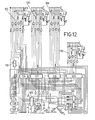
- the block 10 of the central station of the system, through which the communications of the main processor are processed, is shown in the circuit of figure 12.
- This block 10 is consolidated by a communications card having four RS 232 C communication lines.
- the card containing these four communication lines is connected to the bus of the system handled by the main processor 1 and is processed by a sequential protocol which permits information to enter and be received by means of four serial-channeled interruptions simultaneously.
- a different telegraphic rate, which can be selected from bridges in the printed circuit plate can be imparted to each of the lines.
- the circuit 125 constitutes the command register and the control word is initially written therein, determining which of the USART circuits 126, 127, 128, 129 constitutes the register selected for receiving the information. As from this moment onwards, a certain period of time elapses for communicating data or commands to the previously selected via. The time factor is controlled by the monostable circuit 130 which triggers at the written signal disappearing side.
- the "transmission ready” and “reception ready” interruptions of the four communication links are collected in a single interruption.
- the processor once the interruption has been detected, classifies it by reading the port formed of the circuits 131 and 132, proceeding accordingly.
- Each of the links 126, 127, 128 and 129 includes an assembly of adapter circuits 133, 134, 135 and 136 which conveys the signal levels to the standard levels of the international CCITT recommendation V24 equivalent to EIA RS 232 C.
- a current loop can be utilised, employing in this case a +5 V voltage isolated from the general power supply.
- the time base incorporated into this communications card adopts the clock frequency from the bus of the system , which is normally fixed at 3.072 KHz, effecting, via the circuits 137, 138 and 139, a series of divisions to obtain the base frequencies.
- communications can be made at 75, 200, 300, 600, 1,200 and 2,400 bauds, an identical or a different rate can be selected for each of the four links of this communications card.
- Blocks 13 and 14 of figure 1 representing the modems of the system is integrated in the circuit of figure 13, which presents two different sections.
- This circuit represents the emission line 140 and the modem receiving line 141.
- One of the sections of the modem is comprised of a phase-shift-modulator or a FSK modulator which is i m - plemented by the integrated circuit 142 which, in turn, is controlled by the four-linked communications card already described with reference to the circuit of figure 12.
- the operational circuits 143 operates as TD and RTS signal threshold triggers.
- a programmable delay can be generated between the signals RTS and CDS by means of bridges 144 and 144 and 145.
- the modulator 142 operates on time constants formed of two R-C assemblies which determine the signal rate and space periods.
- the rate frequency is determined by the values of the resistor 146, the potentiometer 147 and the condensors 148 and 149.
- the space frequency is determined, in turn, by the values of the resistor 150, the potentiometer 151 and the said condensors 148 and 149.
- the variation can be regulated by suitably adjusting the potentiometers 152 and 153.
- the RTS signal acts on the gate of the field effect transistors FET 154 and 155, blocking then and producing the following effects:
- an operational amplifier 156 installed as an output filter, which is adjusted to a central value: wherein f m represents the rate frequency and f s the space frequency.
- the output threshold incorporates the varistors 157 to avoid field interferences which could originate from the emission cable.
- the other circuit section of the modem consists of the demodulation part.
- the demodulator itself is comprised of the circuit 158 comprising a PLL (phase locked loop) integrated circuit.
- PLL phase locked loop
- This section includes the differential input amplifier 159, two band-pass filters 160 and 161, two band- elimination filters 162 and 163, and an amplifier-cutter circuit 164.
- This circuit permits the pass band to the demodulator 158 to be cut, whose central frequency is fixed by the circuit R-C formed of the condensor 165, the potentiometer 166 and the resistor 167.
- the circuit 158 proportions an open switch coupling detector permitting it to be used along with the level detector 168 to generate the signal CD and produce the line engagement RD at the level deemed fit.
- the received signal is thus at the terminals 169 while the transmitted signal is produced in the terminals 170.
- the signal receiving indication is effected by the electroluminescent diode 171 and, the transmitting indication is effected by diode 172.
- Each of the remote stations of the system is implemented in a single card, although three differentiated sections are distinguished therein:
- the processor used in each of the remote stations is, preferably, the 8,085A circuit 173, which operates assisted by the quartz 174 at a frequency of 6,144 KHz.
- the memory block is positioned in the circuits 175, 176 and 177, and two EPROM memories (such as 2,764), a RAM memory having a capacity of 2 K, and a CMOS can be installed.
- the address decodification is performed by the circuit 178 and the demultiplexing of the minor addresses is performed by the circuit 179.
- the switch assembly 180 and the integrated circuit 181 are provided. These switches assign a position in the hierarchy network controlling the central station and will be useful so that only this remote station attends the communications containing its specific address.
- the block 20 observed in figure 3 consisting of the "watch dog" device is conslidated by the integrated circuit 182, determining a monitor system which, if the maintenance pace is lost, will generate a refreshment of the processor initializing it and returning it to its operative conditions.
- the circuit 183 consists of a wait cycle generator for the processor and acts in a fixed cycle to cycle manner. Suspended from the data bus there is a UART circuit 184 (universal asynchronous receiver-transmitter) communicating the modem of the station.
- UART circuit 184 universal asynchronous receiver-transmitter
- the generation frequency of the communications is produced on the basis of said quartz and effects frequency divisions by the suitable connection of the dividing circuits 185, 186 and 187.
- the analog input section has sixteen impedance input channels, and the terminals are ready to receive 4-20 milliamp current loops.
- the channel multiplexer is formed of the three circuits 188, 189 and 190, canalizing an output link which is applied to the operational amplifier formed of the assembly 191, 192 and 193.
- the signal thus obtained is applied to the analog-digital converter 194 whose conversion table is fed by a duly processed reference system from the integrated circuit 195.
- Both the multiplexer and the converter include a control sequence handled from the station program and which acts via the ports 196 and 197.
- the digital input section of the remote station has sixteen channels galvanically insulated from the rest of the circuit by opto couplers 198 which transmit the signals to the accessing ports to the bus, defined by the circuits 199, 200 and 201.
- This section has four outputs with relays 202 to 205, each of which enters a free potential switching for general uses.
- the relay 202 is normally used to energize the transmitter of the monochannel radio if the network is established by this process.
- the input-output assembly thus formed can be expanded by connecting an extension card which will facilitate the remote station with sixteen outputs per open switch to handle the relays and eight additional galvanically insulated input points, whereby the remote station will achieve a handling capacity of twenty-four digital inputs and sixteen outputs.
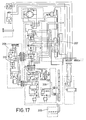
- Figure 17 represents the power supply of the central station.
- the battery assembly 206 will supply power to the station in case of electric failure.
- the transformer 207 has different secondaries to supply the different sections of the central station, both the power section 208 and the supply section of the logic circuits 209.
- the power stage has a protecting and limiting circuit which activates the thyristor 210 via the transistor 211 whereby an optimum security is proportioned to the power supply.
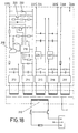
- FIG 18 represents the power supply of the remote stations.
- This circuit includes the network transformer 212 and the rectifier units 213, 214, 215, 216 and 217.
- the rectifier unit 213 supplies current to the serial transistor 218 controlled from the control circuit 219, wherefore a stabilized adjusted voltage of 5 V is obtained at the ttorminals 220 and 221.
- This supply is protected by a thyristor 222 whose port is activated by the transistor 223, protecting the supply from over-voltages.
- a system for the telemetry and remote control of different parameters and variables which is controlled and hierarchized by a central station which, as stated, controls a plurality of remote stations determining a radial hierarchized network, is consolidated.
Landscapes
- Engineering & Computer Science (AREA)
- Computer Networks & Wireless Communication (AREA)
- Physics & Mathematics (AREA)
- General Physics & Mathematics (AREA)
- Selective Calling Equipment (AREA)
- Mobile Radio Communication Systems (AREA)
Applications Claiming Priority (4)
| Application Number | Priority Date | Filing Date | Title |
|---|---|---|---|
| ES540269 | 1985-02-08 | ||
| ES540270A ES8608260A1 (es) | 1985-02-08 | 1985-02-08 | Sistema electronico de telemando y telemedida |
| ES540269A ES8608261A1 (es) | 1985-02-08 | 1985-02-08 | Sistema de telemedida para la prediccion y control de agen- tes polucionantes |
| ES540270 | 1985-02-08 |
Publications (2)
| Publication Number | Publication Date |
|---|---|
| EP0190399A2 true EP0190399A2 (de) | 1986-08-13 |
| EP0190399A3 EP0190399A3 (de) | 1988-06-22 |
Family
ID=26156094
Family Applications (1)
| Application Number | Title | Priority Date | Filing Date |
|---|---|---|---|
| EP85112781A Withdrawn EP0190399A3 (de) | 1985-02-08 | 1985-10-09 | Elektronisches Fernsteuer- und Fernmesssystem |
Country Status (8)
| Country | Link |
|---|---|
| EP (1) | EP0190399A3 (de) |
| AU (1) | AU4826685A (de) |
| BR (1) | BR8505400A (de) |
| DK (1) | DK448385A (de) |
| FI (1) | FI853787A7 (de) |
| GR (1) | GR852438B (de) |
| NO (1) | NO853871L (de) |
| PT (1) | PT81547B (de) |
Cited By (9)
| Publication number | Priority date | Publication date | Assignee | Title |
|---|---|---|---|---|
| WO1992002106A1 (es) * | 1990-07-20 | 1992-02-06 | Universidad De Granada | Red de telemedida y telecontrol para la supervision de redes de abastecimiento de agua |
| FR2709195A1 (fr) * | 1993-08-18 | 1995-02-24 | Baron Frederic | Procédé de transfert, vers un appareil de restitution, de données provenant de relevés fournis par un appareil de mesure. |
| FR2709194A1 (fr) * | 1993-08-18 | 1995-02-24 | Baron Frederic | Procédé de transfert, vers un appareil de restitution, de données de mesure relatives à la consommation d'électricité. |
| ES2078858A2 (es) * | 1993-08-25 | 1995-12-16 | Cerda Juan Nicolas Oller | Dispositivo electronico autonomo de registro y transmision de datos aplicable en aparatos contadors y registradores en general. |
| EP0980046A1 (de) * | 1998-08-12 | 2000-02-16 | Endress + Hauser Conducta Gesellschaft für Mess- und Regeltechnik mbH + Co. | Messeinrichtung zur Ermittlung von physikalischen und/oder chemischen Eigenschaften von Gasen, Flüssigkeiten und/oder Feststoffen |
| EP0992923A1 (de) * | 1998-10-08 | 2000-04-12 | Thomson-Csf | Sytem zur Datenerfassung, -verarbeitung und Steuerung |
| FR2806182A1 (fr) * | 2000-03-13 | 2001-09-14 | Bernard Fort | Procede et systeme pour constituer une plate-forme virtuelle destinee a la gestion des pollutions industrielles |
| US6625548B2 (en) * | 1998-09-08 | 2003-09-23 | Endress + Hauser Conducta Gesellschaft für Mess- und Regeltechnik mbH + Co. | Measuring device for determining physical and chemical properties of gases, liquids and solids |
| FR2853103A1 (fr) * | 2003-03-28 | 2004-10-01 | Planchard Environnement | Systeme d'aide a l'evaluation d'un risque de nuisance dans l'environnement d'un site industriel |
-
1985
- 1985-10-01 NO NO853871A patent/NO853871L/no unknown
- 1985-10-01 FI FI853787A patent/FI853787A7/fi not_active Application Discontinuation
- 1985-10-02 DK DK448385A patent/DK448385A/da not_active Application Discontinuation
- 1985-10-03 AU AU48266/85A patent/AU4826685A/en not_active Abandoned
- 1985-10-08 GR GR852438A patent/GR852438B/el unknown
- 1985-10-09 EP EP85112781A patent/EP0190399A3/de not_active Withdrawn
- 1985-10-18 BR BR8505400A patent/BR8505400A/pt unknown
- 1985-11-22 PT PT81547A patent/PT81547B/pt unknown
Non-Patent Citations (3)
| Title |
|---|
| ADVANCES IN INSTRUMENTATION, vol. 37, part 1, October 1982, pages 491-502, ISA, Research Triangle Park, NC, US; E.F. MOREY et al.: "Digital supervisory control and monitoring system using UHF radio for city of Ft. Lauderdale, Florida" * |
| CONTROL ENGINEERING, vol. 18, no. 1, January 1971, pages 57-76, New York, US; R.L. ARONSON: "Line-sharing systems for plant monitoring and control" * |
| TECHNIQUES CEM, no. 116, March 1983, pages 2-8, Paris, FR; P.R. GOGUEL: "Datamatic et la conduite des réseaux" * |
Cited By (10)
| Publication number | Priority date | Publication date | Assignee | Title |
|---|---|---|---|---|
| WO1992002106A1 (es) * | 1990-07-20 | 1992-02-06 | Universidad De Granada | Red de telemedida y telecontrol para la supervision de redes de abastecimiento de agua |
| FR2709195A1 (fr) * | 1993-08-18 | 1995-02-24 | Baron Frederic | Procédé de transfert, vers un appareil de restitution, de données provenant de relevés fournis par un appareil de mesure. |
| FR2709194A1 (fr) * | 1993-08-18 | 1995-02-24 | Baron Frederic | Procédé de transfert, vers un appareil de restitution, de données de mesure relatives à la consommation d'électricité. |
| ES2078858A2 (es) * | 1993-08-25 | 1995-12-16 | Cerda Juan Nicolas Oller | Dispositivo electronico autonomo de registro y transmision de datos aplicable en aparatos contadors y registradores en general. |
| EP0980046A1 (de) * | 1998-08-12 | 2000-02-16 | Endress + Hauser Conducta Gesellschaft für Mess- und Regeltechnik mbH + Co. | Messeinrichtung zur Ermittlung von physikalischen und/oder chemischen Eigenschaften von Gasen, Flüssigkeiten und/oder Feststoffen |
| US6625548B2 (en) * | 1998-09-08 | 2003-09-23 | Endress + Hauser Conducta Gesellschaft für Mess- und Regeltechnik mbH + Co. | Measuring device for determining physical and chemical properties of gases, liquids and solids |
| EP0992923A1 (de) * | 1998-10-08 | 2000-04-12 | Thomson-Csf | Sytem zur Datenerfassung, -verarbeitung und Steuerung |
| FR2784481A1 (fr) * | 1998-10-08 | 2000-04-14 | Thomson Csf | Systeme d'acquisition de donnees, de traitement et de commande |
| FR2806182A1 (fr) * | 2000-03-13 | 2001-09-14 | Bernard Fort | Procede et systeme pour constituer une plate-forme virtuelle destinee a la gestion des pollutions industrielles |
| FR2853103A1 (fr) * | 2003-03-28 | 2004-10-01 | Planchard Environnement | Systeme d'aide a l'evaluation d'un risque de nuisance dans l'environnement d'un site industriel |
Also Published As
| Publication number | Publication date |
|---|---|
| FI853787L (fi) | 1986-08-09 |
| PT81547B (en) | 1987-01-08 |
| DK448385A (da) | 1986-08-09 |
| EP0190399A3 (de) | 1988-06-22 |
| FI853787A0 (fi) | 1985-10-01 |
| AU4826685A (en) | 1986-08-14 |
| BR8505400A (pt) | 1986-12-16 |
| NO853871L (no) | 1986-08-11 |
| DK448385D0 (da) | 1985-10-02 |
| GR852438B (de) | 1986-02-10 |
| PT81547A (en) | 1985-12-01 |
| FI853787A7 (fi) | 1986-08-09 |
Similar Documents
| Publication | Publication Date | Title |
|---|---|---|
| US3820074A (en) | Remote operating condition data acquisition system | |
| US4203096A (en) | Sensor monitoring alarm system | |
| US4342986A (en) | Central station alarm reporting system | |
| CA1062375A (en) | Operating condition data system | |
| US4748654A (en) | Remote supervisory monitoring and control system | |
| CA1269464A (en) | System for the remote management of lift installations | |
| US4141006A (en) | Security system for centralized monitoring and selective reporting of remote alarm conditions | |
| CN101014173B (zh) | 一种传送通信基站监控数据的方法及系统 | |
| US4928099A (en) | Telemetry system for automated remote calling and central dispatch of services, particularly taxicabs | |
| CA1177140A (en) | Sensing and control system | |
| CA1062792A (en) | Central station system transmission apparatus | |
| JPS58198943A (ja) | 監視システムにおける測定値の伝送方法 | |
| EP0190399A2 (de) | Elektronisches Fernsteuer- und Fernmesssystem | |
| EP0325219A3 (de) | Datensammlung und Übertragungssystem mit Echtzeittakt | |
| EP0050451B1 (de) | Konzentrations- und Erfassungssystem für Alarmdaten | |
| US4821267A (en) | Monitoring apparatus for monitoring the operating condition of transmission facilities of communications transmission technology | |
| GB2237910A (en) | Telemetry transponder | |
| US3699523A (en) | Method and apparatus for addressing different data points from a central station | |
| US3573620A (en) | Security system with inductive to rf communications links | |
| EP0635800A1 (de) | System und Vorrichtung zur Übertragung von Fahrzeugdaten | |
| CN112562276A (zh) | 一种设备故障报警方法及系统 | |
| ES8706988A1 (es) | Perfeccionamientos en los aparatos electronicos para la gestion automatizada de colegios electorales | |
| KR20020007039A (ko) | 수질 오염 원격 조기 경보 시스템 및 그 방법 | |
| US2677119A (en) | Ground controlled aircraft communication system | |
| JPS61184944A (ja) | 電子遠隔制御テレメータシステム |
Legal Events
| Date | Code | Title | Description |
|---|---|---|---|
| PUAI | Public reference made under article 153(3) epc to a published international application that has entered the european phase |
Free format text: ORIGINAL CODE: 0009012 |
|
| AK | Designated contracting states |
Kind code of ref document: A2 Designated state(s): AT BE CH DE FR GB IT LI LU NL SE |
|
| PUAL | Search report despatched |
Free format text: ORIGINAL CODE: 0009013 |
|
| AK | Designated contracting states |
Kind code of ref document: A3 Designated state(s): AT BE CH DE FR GB IT LI LU NL SE |
|
| STAA | Information on the status of an ep patent application or granted ep patent |
Free format text: STATUS: THE APPLICATION IS DEEMED TO BE WITHDRAWN |
|
| 18D | Application deemed to be withdrawn |
Effective date: 19871103 |
|
| RIN1 | Information on inventor provided before grant (corrected) |
Inventor name: FERNANDEZ PERAGON, JOSE-VICENTE Inventor name: MACIAS YANEZ, MANUEL |