EP0190498A2 - Machine d'enveloppement - Google Patents
Machine d'enveloppement Download PDFInfo
- Publication number
- EP0190498A2 EP0190498A2 EP85309038A EP85309038A EP0190498A2 EP 0190498 A2 EP0190498 A2 EP 0190498A2 EP 85309038 A EP85309038 A EP 85309038A EP 85309038 A EP85309038 A EP 85309038A EP 0190498 A2 EP0190498 A2 EP 0190498A2
- Authority
- EP
- European Patent Office
- Prior art keywords
- film
- former
- product
- packaging material
- control signal
- Prior art date
- Legal status (The legal status is an assumption and is not a legal conclusion. Google has not performed a legal analysis and makes no representation as to the accuracy of the status listed.)
- Granted
Links
Images




















Classifications
-
- B—PERFORMING OPERATIONS; TRANSPORTING
- B65—CONVEYING; PACKING; STORING; HANDLING THIN OR FILAMENTARY MATERIAL
- B65B—MACHINES, APPARATUS OR DEVICES FOR, OR METHODS OF, PACKAGING ARTICLES OR MATERIALS; UNPACKING
- B65B9/00—Enclosing successive articles, or quantities of material, e.g. liquids or semiliquids, in flat, folded, or tubular webs of flexible sheet material; Subdividing filled flexible tubes to form packages
- B65B9/06—Enclosing successive articles, or quantities of material, in a longitudinally-folded web, or in a web folded into a tube about the articles or quantities of material placed upon it
- B65B9/067—Enclosing successive articles, or quantities of material, in a longitudinally-folded web, or in a web folded into a tube about the articles or quantities of material placed upon it the web advancing continuously
Definitions
- This invention relates generally to wrapping and packaging machines and more particularly concerns a horizontal wrapping machine utilizing a microprocessor-based control system (MBS) and method wherein separate drives and operating temperatures in the wrapping machine are independently servo controlled.
- MFS microprocessor-based control system
- a continuous film of packaging material is supplied from a roll and drawn past a former which shapes the film into a continuous tube of packaging material.
- Products to be wrapped are supplied through the former into the tube of packaging material such that the products are spaced apart from one another in the tube.
- the seam of the tube is longitudinally sealed and the tube of packaging material is then cut and transversely sealed as each product, carried within the tube, passes through a sealing and cutting station. In this way, an individual sealed package is formed about each product.
- the products to be packaged are supplied to the former on an infeed conveyor in the form of an endless chain having a number of product pushers extending from the chain.
- Each adjacent pair of pushers defines an infeed conveyor flight, and each product is advanced to the former in an individual conveyor flight.
- the film is formed in the former such that the lateral edges of the film, when the tube is formed, extend downwardly from the center of the film tube in a side-by- side relationship.
- a number of pairs of finwheels rotating about vertical axes in a finwheel assembly engage opposite sides of the downwardly extending pair of film edges to drive the film toward the cutting and sealing station.
- At least one pair of finwheels in the finwheel assembly may be heated, serving to heat seal the downwardly extending film edges together to seal the tube of heat sealable film.
- Other so-called cold-seal film do not need heat but instead use the pressure of one or more finwheel assemblies to create the seal.
- cut/seal heads one containing a knife member and the other an anvil, are rotated into engagement with the film tube between each successive pair of products.
- the cut/seal head may also include heated members so as to seal the film as it is cut to thereby form individual sealed packages, each containing a now-wrapped product.
- a typical horizontal wrapping machine has been driven by a single motor through a single line shaft.
- separate gear boxes, belt and pulley, and chain and sprocket drives are coupled to the main shaft and the infeed conveyor, the finwheel assembly, and the cut/seal heads.
- Another problem with prior horizontal wrapping machines is a difficulty in reorienting the phasing of the cut-heads relative to the desired cut locations between the products in the tube of packaging material.
- the velocity profile of the cut-heads is automatically adjusted for correct phasing when the package length is changed.
- the present wrapper includes three separate closed loop servo- controlled motor drives for the infeed conveyor, for the finwheel assembly which drives the film, and for the cut- heat drive, respectively.
- Each closed loop servo control circuit includes a motor which is driven by a summing-amplifier.
- the summing-amplifier receives as a feedback signal the actual motor velocity and receives as a control signal a desired motor velocity.
- Each servo control circuit is thereby operable to maintain its associated motor at the velocity established by the desired velocity control signal.
- Each of the servo control circuits forms a part of a microprocessor-based controller which coordinates the motor speeds to effect the desired synchonous operation of the horizontal wrapping machine.
- the package To produce an acceptable packaged product, it is necessary, within selected tolerances, for the package to contain a certain desired length of film and for the product to be at a desired location relative to the length of film, which is formed into a complete package. There is an additional positioning requirement which arises typically due to the provision of printed material on the packaging film. This requirement is that each length of film used to form a package should have thereon the properly-oriented printed matter for the package.
- the product to be packaged is a candy bar having a length of two and one half inches
- the length of film used for the package, four inches is the cut length of the package.
- the length of the candy bar, two and one half inches is designated the product length.
- a candy bar wrapper typically contains printed matter including the name of the candy bar and its manufacturer, and perhaps a list of ingredients, etc.
- the name is typically in large letters extending across most of the length of the product. In order for the product name to be properly located on each package, not only must the package length be approximately equal to the desired cut length, but also the positioning of the product and cut relative to the printed matter must be approximately correct so that the product name lies on the product and not across a cut location on the film.
- each cut length is defined as beginning at a fixed relationship to an eyespot
- the distance along the film tube from the eyespot to the trailing edge of the product is termed the product orientation.
- the master control for each of the servo motors is derived from a master tachometer on the film drive mechanism.
- a microprocessor-based controller receives the output from the master tachometer which relates to film speed. Based upon this actual film speed, the controller outputs the desired product infeed conveyor speed to the infeed conveyor motor summing-amplifier and outputs the desired cut/seal speed to the cut/seal head motor summing-amplifier.
- the desired infeed conveyor speed must be set to be a proportion of the actual film speed so that exactly one product is delivered to the film former for each cut length of film which passes the film former.
- the controller varies the desired velocity signal supplied to the infeed conveyor servo loop to correct for errors in product orientation relative to the film.
- the cut/seal heads may be viewed as operating in two modes. During a cut and seal mode, wherein the cut/seal heads are in contact with the film, their film-engaging faces must move at the same rate as the film. During what is termed a return mode, the cut/seal heads are not contacting the film. They must move at a different rate of speed, usually a higher rate, in order to be repositioned for the next cut and seal phase.
- the microprocess-based controller supplies a desired cut/seal-head velocity to the cut/seal head servo motor amplifier during a cut cycle to move the film-engaging surfaces at a rate substantially equal to the film speed in the direction of film travel.
- the controller supplies a desired velocity signal to the cut/seal head summing-amplifier, which is derived from the film velocity, such that the cut-heads are in proper position for the next cut cycle.
- the present horizontal wrapper having a control arrangement as described, overcomes the above-enumerated disadvantages of prior, mechanically synchronzied, horizontal wrapping machines. Since the drive motors for the different sections of the present horizontal wrapper are separately servo controlled, the different sections of the wrapper must be operated independently and may be operated in forward or, in some cases, in reverse. Due to the independent control of the cut/seal head drive, the return velocity of the cut/seal heads may be individually controlled. Likewise, the independent control of the product infeed conveyor motor permits variation of pusher position and product orientation relative to film cut lengths.
- prior horizontal wrappers abrupt changes to correct orientation errors are not possible. For example, if the product orientation degrades due to film splicing, the error remains and is corrected only gradually, at best, as packages are produced by the machine.
- product orientation corrections are made by adjusting the film feed, based upon eyespot measurements on the film. If an attempt is made to adjust the film too rapidly, the film can be torn or broken and product can slip in the film tube. In the present system, the product infeed is adjusted in order to alter the product registration.
- auxiliary functions such as, for example, a card feeder for placing a paper card beneath each product introduced into the film former, without several additional components to link the auxiliary function drive to the main drive shaft of the machine in proper synchronization.
- synchronous auxiliary devices can be added to the horizontal wrapper using an individual servo control with the synchronization derived electronically from the film travel.
- adding auxiliary functions in the present horizontal wrapper does not require resizing a main drive motor, since separate drive motors are used for the different functions.
- an automatic splicer on a wrapping machine, for example, a new roll of film is spliced onto the end of a previous roll to maintain continuous machine operation.
- the eyespots on the rolls of film generally are not in a correct position, or they may be omitted entirely from the leading or trailing edge of one of the film rolls.
- the prior horizontal wrappers were unable to quickly adapt to this condition, resulting in orientation errors for several packages when then had to be rejected.
- the controller determines the product orientation relative to the cut length to establish, if possible within acceptable tolerances, a desired cut point, which may differ from the eyespot location.
- the present horizontal wrapping machine provides a number of additional advantages unavailable in prior art horizontal wrappers.
- a film travel indicator is utilized to detect film breakage.
- precisely controlled acceleration and deceleration of the film is possible when film speed is to be changed. For example, if new operator-selected product packaging rate is introduced into the machine controller, a controlled ramp-up of film velocity can be made in order to prevent tearing or breaking of the film.
- An immediate response when one parameter is varied is not required since there is not a single mechanical linkage connecting the various portions of the machine.
- the longitudinal seal is affected by at least one heated pair of finwheels in the finwheel assembly and the transverse seal by heated rotatable cut/seal heads. It is necessary to determine if the heat applied to the film is within a safe operating range. This may be accomplished by monitoring the time- temperature product of the heat applied to the film to see if it is within a safe band. This safe band of time- temperature product is a range of temperatures for a particular film speed at which the heating elements will neither burn the film nor fail to obtain a complete bonding of the film. In the present horizontal wrapper, the film rate is monitored as is the temperature of each heating element. Where the applied temperatures are outside the acceptable range of temperatures for the film speed at which the machine is operated, a warning is given and the packaged products may be rejected.
- the present invention leads to significant improvements in operation as contrasted with prior art electro-mechanical horizontal wrapping machines.
- the operator inputs for wrapper speed, temperature, package length, and cut position are all digital quantities, greater accuracy and repeatability can be achieved. Such accuracy was difficult, if not impossible, to achieve in prior art wrapping machines which used potentiometer settings and the like to effect a fine-tuning of these parameters.
- the present invention provides increased information to the machine operator.
- a digital display on the control panel is used to present various error messages, temperature set points, wrapper speed, mode of operation, cut-length, etc.
- the control panel used with the present invention permits quick and easy inputting of the initial set-up parameters for each product. The operator is presented with "prompts" which are easy to understand and follow when performing these functions.
- wrapper speed and temperature set points can be changed while the wrapper is running simply by entering new data values from the operator's keyboard.
- Product placement position and cut position can be incrementally advanced or retarded in small increments merely by depressing appropriate keys on the control panel.
- Still further features and advantages attendent in the present invention are that the changeover time of a machine for packaging different products is reduced because the new information for various products is either selected from a pre-loaded memory or is entered from a keyboard. Those would be the only steps necessary, provided the film former and the infeed flight length do not require change.
- the microprocessor controller of the present invention permits a great deal of flexibility in the operation and control of the wrapper system. This is due to the fact that changes in operating mode can be accomplished merely by replacing printed circuit cards in a cardrack rather than undertaking to do significant mechanical readjustments and alignments. Furthermore, the conventional belts, chains, sprockets, bearings, etc. associated with prior art systems are significantly reduced using the teachings of this invention, thus simplifying maintenance and repair.
- the microprocessor controller also is preprogrammed with diagnostic routines which become available to the repair technician, via the control panel, to permit more rapid location of failed components, should they occur.
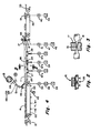
- a horizontal wrapping machine 10 includes a former 11 for shaping a continuous film 12 of packaging material which is drawn past the former 11 from a roll of sheet film 13, which may be printed or unprinted.
- Products 14 to be wrapped are fed into the former 11 and carried within the packaging film tube 16 formed by the former 11.
- the products 14 are carried within the tube 16 spaced apart from one another past a sealing and cutting station at which a pair of opposed sealing and cutting heads 17, 18 cut and seal the film tube as each product moves past the cutting and sealing station to form discrete sealed product packages 19.
- the products are received from a suitable supply source conveyor 21 on an endless conveyor 22 termed the infeed conveyor and which is divided into a series of flights by a number of product pushers 23.
- a suitable supply source conveyor 21 on an endless conveyor 22 termed the infeed conveyor and which is divided into a series of flights by a number of product pushers 23.
- Each product 14 is carried in a flight on the conveyor with its trailing end resting against a pusher 23.
- the products 14 are introduced into the interior of the tube 16 of film formed by the former 11 by advancing the products 14 into the former. Each product is then received on, and carried along by, the interior bottom surface of the film tube 16.
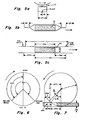
- the film tube 16 is shown as being formed into a generally rectangular shape, having its two edge portions formed into downwardly extending strips 26 ( Figure 2).
- the film is driven by a suitable drive arrangement such as a finwheel drive or a band sealer.
- a suitable drive arrangement such as a finwheel drive or a band sealer.
- separate motor-driven finwheel assemblies advance the film tube 16 toward the cut/seal head 17, 18 by gripping the downwardly extending adjacent pair of film (edges) 26.
- the finwheel area 24 includes three pairs of opposed finwheels 27, 28 and 29.
- Each finwheel in each pair of finwheels rotates in an opposite direction, firmly gripping the film (edges) 26 therebetween, moving the film tube 16 toward the cut-heads 17, 18.
- the middle pair of finwheels 28 may be heated to seal the edges of film 26 together to close the film tube 16.
- the now-sealed tube 16 containing the spaced apart products 14 is advanced by the finwheels past the cut/seal head 17, 18.
- the cut/seal heads are rotated in opposite angular directions to meet and engage the film tube 16 after each product moves past the cutting and sealing station.
- the cut/seal heads, when in engagement with the film tube 16, must move at substantially the same linear rate as the film and coact to compress the film tube together into a flattened condition.
- Each of the cut/seal heads 17, 18 may be heated and the compressed film tube is sealed as it is cut, thereby enclosing each product in an enclosed, sealed package.
- the upper head 17 contains a knife blade 31 extending from its film-engaging surface.
- the lower cut/head 18 contains an anvil 18. The knife and anvil coact to cut the film as it is sealed ( Figure 3), all as is well known in the art.
- the packages 19 are carried from the cutting and sealing station by a discharge conveyor 32, which operates at a higher rate than the rate of travel of the film tube 16.
- the products 19 are then discharged onto a suitable receiving apparatus 33.
- a motor 34 is coupled to a drive shaft of the conveyor (not shown). As shall be described in more detail hereinafter, the motor 34 is driven under closed-loop servo control.
- the infeed conveyor's "actual velocity" feedback signal used in the servo loop is provided by a tachometer 36 on the motor 34.
- the finwheel assemblies 27, 28 and 29 are likewise driven by motors 37(a), 37(b) and 37(c) which are under closed loop servo control.
- the finwheel motors 37(a) - 37(c) have an associated tachometer 39 for providing an "actual velocity" feedback signal for the finwheel motor servo loop.
- the cut/seal heads 17, 18 are each driven in unison by a single motor 41, which is also operated under closed loop servo control.
- the motor 41 has an associated velocity-sensing tachometer 42 for providing the actual cut/seal head velocity feedback signal for the servo loop.
- the discharge conveyor 32 is driven by a motor 40, operated under closed loop servo control.
- the discharge conveyor motor 40 has an associated tachometer 45 for providing the actual discharge conveyor velocity feedback signal for the servo loop.
- the infeed conveyor speed, and hence the product feed rate into the film former and film tube 16 is controlled to be dependent upon the film speed as it moves past the former and past the cutting and sealing station.
- the cut-head velocities, for each of the cut-head phases are dependent upon the film velocity.
- an encoder 43 rides directly upon the film as it passes around a rubber idler roller upon leaving the roll 13. The movement of the film and the production of encoder pulses by the encoder 43 are directly related to the film travel over the idler roller.
- an encoder 46 is coupled to the drive shaft of the infeed motor 34.
- the angular position of the cut/seal heads is derived from the output of a resolver 47 mounted on the drive shaft of the cut-head motor 41.
- each product 14 it is important to obtain the proper orientation of each product 14 relative to a cut length of film, which is the amount of film used in each package 19. It is also important to seal and cut the tube of film 16 with the cut/seal heads 17, 18 at the proper cut point between the products in the film tube.
- the film cut lengths are defined by eyespots on the film 12 when it is necessary to maintain registration between the product and its wrapper. The spacing between the eyespots defines the cut lengths of the film. These eyespots are sensed by a sensor 48 to provide film position information to the control system for the horizontal wrapping machine.
- a second sensor an infeed conveyor pusher sensor 49, provides the control system with infeed pusher position information.
- the film and product conveyor position information permits the positioning of the products 14 in the proper orientation relative to the cut lengths of film and also permits the timely operation of the cut/seal heads 17, 18 to seal and cut the film tube 16 at the proper cut points to form the product packages.
- the controller for the horizontal wrapping machine 10 is illustrated, in conjunction with certain of the controlled elements of the machine.
- the controller indicated generally by numeral 50 is a microprocessor-based controller ( M BC) including a central processing unit (CPU) 51 and a universal memory 52 coupled to a common bus 53.
- M BC microprocessor-based controller
- CPU central processing unit
- universal memory 52 coupled to a common bus 53.
- the controller 50 includes an operator interface section 54 and a temperature control section 56.
- the operator interface section 54 includes a keyboard entry device 57 and an alpha/numeric display device 58 coupled through a display and keyboard control circuit 59 and a serial input/output circuit 61 to the system bus 53.
- a processor associated with the remote control panel 54 is operable to provide display prompts to the machine operator on the display 58 so that the operator can input desired machine operating parameters to the processor through the keyboard.
- the temperature control section 56 includes circuitry for providing closed loop control of the heaters on the upper and lower cut/seal heads 17, 18 and the finwheels 28.
- the cut/seal heads and finwheels each contain heaters 62, 64 (not shown in Figure 1), respectively.
- the cut-heads and finwheels carry temperature sensors 66 and 68, respectively.
- the outputs of the temperature sensors 66, 68 are coupled through a temperature sensor interface circuit 69 to the bus 53.
- the processor 51 provides heater activation signals to the heaters 62, 64 by way of the bus 53 through a triac output circuit 71.
- the heater activation signals are based upon the temperatures of the cut/seal heads and finwheels as provided by the temperature sensors 66, 68.
- the temperatures of the cut/seal heads and finwheels are presented by the processor 51 to a temperature display 73 through a serial I/O circuit 74 which is coupled to the bus 53.
- the microprocessor-based controller 50 further includes an infeed conveyor motor servo control circuit 76, three finwheel motor servo controls (only one of which is identified as 77), film tension motor control 72, a cut/seal head motor servo control 78 and a discharge conveyor motor servo control 79.
- the infeed control 76 includes a summing-amplifier 81 which receives a desired infeed velocity signal from the processor 51, via the bus 53 and a digital-to-analog converter 82. As previously described, the feedback loop from the motor to the summing-amplifier is completed by a velocity sensor (tachometer) 36 which provides an actual infeed velocity signal to the summing-amplifier 81.
- one of the finwheel servo circuits 77 includes a summing-amplifier 83 which receives a desired finwheel velocity signal from the processor via the digital-to-analog converter 82.
- the feedback loop is completed by a tachometer 39 which couples the finwheel motor speed to the summing-amplifier 83.
- the other two finwheel motor controls use current feedback as a means of controlling their respective motors.
- the cut/seal head motor servo control circuit 78 includes a summing-amplifier 84, which receives a desired velocity signal from the processor via the digital-to-analog converter 82.
- the cut/seal head servo loop is completed by the tachometer 42 which is coupled to the summing-amplifier 84.
- the discharge conveyor servo 79 includes a summing-amplifier 86, which receives a desired discharge conveyor motor velocity signal from the processor 51 by way of the digital-to-analog converter 82.
- the discharge conveyor servo loop is completed by the tachometer 45 which is coupled from the discharge conveyor motor output to the summing-amplifier 86.
- the infeed encoder 46 indicative of infeed conveyor travel is coupled through a timing and counting circuit 87 and the bus 53 to the processor 51.
- the film motion encoder 43 indicative of film travel is also coupled through the timing and counting circuit 87 to the processor 51.
- the cut/seal head position sensor, i.e., the resolver 47, is coupled to the processor through a resolver-to-digital converter 88 via the bus 53.
- the eyespot sensor 48 for detecting eyespots on the film 12 is coupled to an interrupt controller circuit 89 as is the pusher sensor 49 which senses the pushers on the infeed conveyor.
- the interrupt control circuit 89 also receives a signal from a film splice eye 115.
- the interrupt control circuit 89 produces hardware interrupt signals to the processor via the bus 53 when the eyespot sensor senses an eyespot on the film, when the pusher sensor 49 senses a pusher on the infeed conveyor at the pusher sensor location, and when the splicer eye 15 senses an eyespot.
- Interrupt routines are initiated based upon a counter in the circuit 87 coupled to the film motion encoder 43.
- Another interrupt routine is initiated based upon a 1 ms. timer in the CPU 51.
- the primary function for the controller 50 in the operation of the horizontal wrapping machine 10 is to maintain proper product/film flow.
- the control problem may be considered to be two distinct sub-problems. The first is to cause each product to be oriented properly with respect to the eyespots on the film (product orientation). The second sub-problem is to cause each cut to be oriented properly with respect to the eyespots (cut orientation).
- the plural motors i.e., the infeed, tension, finwheel and cut/seal head motors, must be synchronized in order to provide these two necessary orientations to properly package a product.
- Film travel is used as the master input to control the synchronization of the product infeed and the cut/seal head movement.
- each cut length C L is defined as extending from one eyespot to an adjacent eyespot on the film.
- Other film registrations are possible, such as the case in which each cut length begins at the midpoints between eyespots. Film registrations other than that discussed herein (eyespot to eyespot) may be readily accommodated by utilizing an appropriate offset term for the location of the cut lengths relative to the eyespots.
- the processor sets each cut length equal to an operator-entered value.
- the software can be considered as comprising six main routines:
- Each of the above main routines incorporates a plurality of subroutines. Set forth below under each of the main routines is a designation of the particular subroutines used in that main routine.
- the "NORUN" routine covers the power-up sequence and the initialization of the hardware and software, readying the system for normal operation.
- a test is made to determine whether the AC power is on. If not, nothing happens and the system remains idle until the power is applied. Assuming that the power-on switch has just been closed, certain registers and flags are cleared and the microprocessor is readied for entry of set-up information. Specifically, in designing the system, an assumption is made that upon power-up, it will be desired to run the same product through the wrapper as had been involved prior to turning off the power switch. Thus, certain parameters which had been stored in a non-volatile memory are called up and calculations are made defining various parameters to be employed.
- the wrapper status is set to specify the "NORUN” routine.
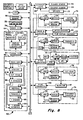
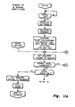
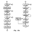
- a test is then made to determine whether the control panel is connected and if it is a test is made to determine whether the emergency switch is on ( Figure 11(b)) and operations proceed based upon the condition of that switch. If the control panel is not connected, a test is made to determine whether the local start switch on the wrapper is on or off. If it is on, signifying that the wrapper is to be run, the status message "NORMRUN" is presented and the subroutine "HOME" ( Figures 15(a), (b) & (c)) is entered.
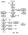
- a test is made as to whether a command code is available from the RS232 serial I/O port from the control panel. If such a command code is present, it is sequentially examined to determine whether it is a "SETUP" code, a "DIAGNOSTIC” code, a "JOGFIN” code, or any one of the other codes identified in the flow diagram of Figures (11(b) and 11(c). When any one of these codes are detected, an appropriate corresponding status message is presented and a jump is made to an appropriate routine or subroutine. Following the completion of called routines or subroutines, a return is made to the operation on Figure 11(d) "CALLUPJAWTEMP".
- This routine compares the temperature of the cut/seal head with a predetermined set point and turns off the current through the cut/seal upper jaw heaters if the temperature is above the set point.
- the subroutine is also effective to turn on current through the cut/seal upper jaw heaters when a temperature comparison reflects that the actual temperature of the head is below the set point.
- the routine LOJAWTEMP operates in a similar fashion with the lower jaw heaters.
- the "C A L L FINTEMP" subroutine works in much the same fashion. It compares the actual temperature of the finwheels with a predetermined set point and appropriate commands are sent from the CPU 51 to the triac card 71 whereby the temperature of the finwheels are maintained at the predetermined set point temperature.
- the further subroutine "TEMPDISP" and "CONTPAN 232" are executed.
- the TEMPDISP routine causes actual temperature readings to be presented on the machine display.
- the CONTPAN232 subroutine oversees the transmission of data between the operator control panel and the high speed wrapper. Following the latter operation, the sequence returns to the point where the wrapper status is set to "NORUN" (see Figure 11(a)).
- the function of the "HOME" subroutine is to bring yarious operational elements of the machine into position before entering into the normal running mode.
- the "Cut Seal in Place” flag, the "Infeed in Place” flag, and the “Film in Place” flag are all cleared upon entry into the "HOME” subroutine and then a test is made to determine whether the "Infeed” flag is set or cleared. If it is cleared, the cut/seal motor and the film drive motor are enabled, forrowed by the setting of the "Infeed In Place” flag. If the "Infeed” flag had already been set, all the motors would be enabled. In either case, a signal is set to cause the finwheels to engage the film edges 26 following the passage of the film over the film former. A zero command is then sent to all motors, the zero command corresponding to zero speed.
- the so-called "Cut Seal In Place” flag is tested and if it is not, a speed signal is sent to the cut seal motor servo-control 78 via the D/A converter 82 causing the cut/seal motor to run at a fixed low.
- the output of the resolver associated with the cut/seal head is monitored, that output being indicative of the angular position of the cut/seal head.
- This angular position is tested to determine whether it has reached its "HOME” position and when the "HOME" position is reached, a zero command is sent to the cut/seal motors telling them to stop. Because at this time the cut/seal head is at its "HOME" position, the "Cut Seal In Place” flag is set. Then, power to the motor is itself cut off.
- an encoder is associated with the pusher drive motor and produces pulses corresponding to the travel of the infeed conveyor. This position information is reviewed and if it is determined that the infeed conveyor is at its home position, a zero command is sent to the infeed conveyor motor to stop its motion, followed by the disabling of the power to the motor itself. Following that, the "Infeed In Place” flag is set to indicate that the "HOME" position for the infeed conveyor had been achieved.
- the infeed conveyor has an on/off switch whose status is reflected by the "Infeed” flag.
- the "Infeed” flag is tested and if set, all motors are enabled. However, if that flag is not set, all motors except the infeed conveyor motor are enabled. Control is then returned to the main NORUN routine ( Figure 11(a)) and then on to the NORMRUN routine.
- the HOME subroutine results in prepositioning of (1) the cut/seal head, (2) the film, and (3) the infeed conveyor. Once this homing operation is completed, the system is poised and ready to move into its normal running mode.
- the temperature sensors 66 and 68 communicate with the CPU 51 by way of the temperature sensor interface 69.
- a RS 232 port allows data transmitted from the temperature sensor interface, via the standard bus 53, to be displayed on the temperature display panel 73.
- a test is made to see if the serial I/O port 74 is busy and, if so, control returns to the main program.
- the point in time will be reached when the serial I/O port is not busy and, at that time, a digital value corresponding to temperature is transmitted character by character to the display panel while the control system continues to perform its functions on a simultaneous basis.
- a carriage return (CR) character is sent to the display as a command and the "Temp Int Done" flag is set. In this fashion, temperature readings are presented to inform the operator of the temperatures.
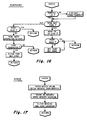
- the subroutine captioned "SPEED" illustrated in Figure 17 of the drawings indicates the manner in which digital values corresponding to desired wrapper speed in packages per minute are stored for later use by the control system of the present invention. It will be recalled in the "NO R UN" routine, periodically a test is made to determine whether a command code is being received from the control panel RS 232 serial I/O port. If so and a test reveals that it is a so-called "SPEED" code, then the subroutine reflected in Figure 17 is executed. Specifically, the digital value corresponding to a predetermined speed is retrieved from the received data buffer and stores away in a predetermined memory location. Following that, the command code is cleared and a return is made to an appropriate point in the program.
- the active information subroutine permits information useful to the operator to be periodically withdrawn from various points in the memory and transmitted to a utilization device.
- a utilization device For example, any piece of digital equipment capable of communicating with the CPU 51 via the serial I/O port 74 or either of the optional serial I/O ports can extract data from the universal memory 52 after it has been placed there from various sensors and encoders used in the system.
- the command code from the RS232 port may also test out to be a "Reset Splicer” code. This code is activated by the operator whenever a new roll of film is installed on the wrapper. The resulting “RESPLICE” subroutine merely results in the setting of the so-called “Splice Enable” flag. The manner in which that flag is used will become more apparent as the discussion of the overall software progresses.
- the position of the Stop switch is tested, and if it is not active, a test is made to determine the presence of a command code. If a command code is detected and it turns out to be a STOP command, the finwheel speed is ramped down and tested to determine whether it is yet at a zero-speed value. Once the finwheel is at a stop, the finwheel motors are disabled as is the motor associated with the film tension mechanism. If no command code is present, the next test is to determine whether the system is in the STOP mode. If it is, again the finwheel speed is ramped down to zero. If not, however, control loops back to the point where the test is made to determine whether the finwheel is at its desired speed. Once the Stop switch is operated, the speed ramps down until the zero-speed condition is reached. The finwheel stops without a particular positional relationship to infeed, cut/seal or eyespot.
- the cut/seal head can also be operated in a Jog mode, meaning that so long as the Cut/Seal Jog switch is closed, the cut/seal motors will be enabled.
- the low speed command is sent via the D/A convertor 82 to the cut/seal head motor 41.
- the "UPJAWTEMP”, "LOJAWTEMP”, “FINTEMP”, TEMPDISP” and "CONTPAN232" subroutines will be executed with control looping back to the point where the cut/seal head motor is enabled.
- a ZERO-SPEED command is sent to the motor control causing it to stop. Once stopped, the cut/seal motor is disabled and control returns to the appropriate point in the " NOR UN" main routine.
- the cut/seal head stops without parLicuiar relationship to infeed, eyespot or cut/seal home position.
- the JOGWRAPPER subroutine functions very much like the NORMRUN routine, which is described in detail immediately below. The only essential differences are that in the JOGWRAPPER mode a fixed low wrapper speed is mandated and that the JOGWRAPPER routine is active only while the remote control panel Start switch is depressed. Hence, it is not deemed necessary to provide a further explanation of the JOGWRAPPER subroutine because it is adequately covered in the following NORMRUN description.
- MIS Management Information System
- Options 9 and 8 are similar to Option 10 and permit a user to tie various types of digital data processing equipment for two-way communication with the wrapper. In this fashion, a remotely-located device can be used to operate the wrapping machine.
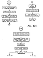
- the "CUTSEAL" subroutine reflected in the flow diagrams of Figures 26(a) - (d) reflect the manner in which the speed profile or epicycle of the cut/seal head is controlled.
- the problem to be solved is to ensure that the cutting knife and the anvil come together with the film to be cut travelling at the same speed and with the cut being made at a desired point on the film between adjacent products. Because the angular distance that the anvil and cutting knives must travel is greater than the cut length of the film, the average angular velocity of the cut/seal head must be greater than the linear velocity at which the film is moving. Nonetheless, at the time that the cut/seal head assembly contacts the film, both must be travelling at the same velocity. Hence, there is the need for a controlled angular velocity profile for the cut/seal head.
- the head assembly may only include one blade member allowing its 360 0 of periphery (a 1-up head) or, alternatively, it could be a 2-up head where two blades are spaced 180° apart about the periphery. Additional cutting blades may also be employed, it being understood that, when they are, they are spaced equally about the periphery of the rotating head.
- the epicycle of the cut/seal head is •divided into two basic segments, namely, the cut phase, C, and the returnphase, RN, (Fig 6).
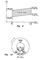
- the cut phase is, in turn, divided into four discrete zones referred to as "dive-in”, “lead seal”, “trail seal”, and “exit”.
- the length of each of these zones is arbitrarily defined for a particular cut/seal head configuration. in Figure 10, the point where the actual cut is assumed to take place is represented by a broken line. This line divides the lead seal and trail seal zone.
- the return phase both in length and speed profile, is dependent upon the particular cut/seal head configurations employed, i.e., whether it is a 1-up head, a 2-up head, etc.
- the first operation to be performed upon entry into the "CUTSEAL" subroutine is to call the resolver (RDRESOLVER) which provides an indication of the actual angular position of the head relative to an arbitrary reference point.
- RDRESOLVER resolver
- the dive-in table may have a starting address of zero.
- the resolver value obtained during the call "RDRESOLVER" operation is added to the starting address, and then the resolver value at the start of the dive-in phase is susbtracted.
- the net result, then, is the actual distance of the cutting blade into the dive-in zone and associated with that actual distance value is a speed value in the look-up table.
- what is stored in the look-up table is a "motor ratio" which, when multiplied by the speed reflected by the master tachometer on the wrapper drive, yields the motor speed command for the cut/seal head motor control 78.
- the termination of the leadseal zone ends at the point at which the cut is made. That also marks the start of the so-called trailseal zone.
- the trailseal zone is basically a mirror-image of the leadseal zone in that it, too, relates to a velocity profile which will ensure that the head and the film are moving at the same linear velocity until the end of the trailseal where the head again lifts free of the film.
- the exitphase zone is a mirror-image of the dive-in zone.
- the control was such that the return speed was reduced to the point where it equalled the linear velocity of the film.
- the speed profile is such that the angular velocity of the cut/seal head is increased from that corresponding to the linear velocity of the film to the angular velocity of the head during the return phase.
- the angular velocity of the cut/seal head during the return portion of the cycle remains constant, with only minor corrections being made, either positively or negatively, to the base ratio so as to achieve positional correction.
- the resolver value is substracted from the resolver value pertaining to the actual angular position of the head at the beginning of the return zone and that answer is used to address a table which, in this instance, contains values corresponding to what the film position should be at this particular positioning of the cut/seal head.
- the contents of the film counter is read, that value providing an indication of the actual film location.
- the actual location count is subtracted from the film count corresponding to the desired position, and a test is made to determine whether that difference results in a negative or a positive answer. If it is a negative answer, it is known that the actual position is in advance of the desired position and that slow-down should take place. Contrawise, if the results of the subtraction yields a positive number, it is known that the actual position is less than the desired position and that speed-up is called for. Having determined the direction (increase or decrease) of the speed change, it is also necessary to know the magnitude of the change. Moreover, the algorithm employed determines the shortest distance in which the correction is to be made.
- This latter aspect is implemented by adding a count corresponding to one full flight, i.e., the distance between cuts, to the actual position count value followed by subtracting the desired position film count therefrom. A comparison is then made between these two values and, if the former is less than the latter, it is the sum of the actual count plus one flight less the desired count, which is used as the position error value. However, if the comparison reveals that the former is larger than the latter, then the first value computed is employed as the position error. In either case, once the position error is computed, it is employed as an address for accessing the return base ratio table.
- a motor ratio value when multiplied by the signal proportional to film speed obtained from the master tachometer on the wrapper, a speed command is generated which, when applied to the velocity servo associated with the cut/seal head, causes the cut/seal head to rotate at a particular angular velocity corresponding to its actual position in the epicycle.
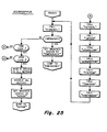
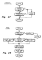
- the "FINWHEEL" subroutine of Figure 27 reflects a fairly simple programming concept. Specifically, when this subroutine is called, a test is made to determine whether the desired finwheel speed is greater than or less than that determined by the present speed command. If it is neither greater than nor less than the present speed command, then it is known that the finwheels are rotating at the desired speed and no further speed adjustment need be made. However, if the desired speed if greater than the present speed command or if the present speed command is greater than the desired speed, the "RAMP" subroutine is executed.
- the "RAMP" subroutine itself is shown in Figure-28 of the drawings.
- a test is made of the ramp time counter to determine if it has timed out. If not, it is decremented and a return is executed.
- the ramp time counter reads zero, a test is made to determine whether the desired finwheel speed is less than that dictated by the present speed command in place. If not, a speed-up is dictated and this is accomplished by incrementing the present speed command by one unit. On the other hand, if the desired speed had been tested and found to be less than the present speed command, then it is known that the finwheel is moving at too high a rate and speed adjustment is accomplished by decreasing the present speed commend by one unit. After the incremented or decremented speed command is sent to the finwheel motors, the ramp time counter is again reloaded and control returns to the point in the program where the "RAMP" subroutine was first entered.
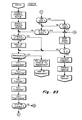
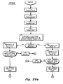
- the "INFEED” subroutine used in the "NORMRUN” main routine is reflected by the flow diagram of Figures 29(a) and (b). It is the general purpose of the "INFEED” subroutine to adjust the speed at which the infeed conveyor is operating so that the arriving products will be properly oriented and aligned with the eyespots on the film and, ultimately, with the operation of the cut/seal head assembly.
- the " RDE YECNTR" subroutine is executed.
- the pusher location is determined by executing the "RDPUSHENC” subroutine, which relates to the encoder device associated with the infeed chain.
- the film count (FC) obtained from the film counter is susbtracted from the normalized and offset pusher count value (PC), and a test is made to determine whether that difference yields a positive or a negative result. If positive, the film count plus a count corresponding to one flight is subtracted from the pusher count. If this computation results in an answer that is smaller in magnitude than that achieved during the preceding subtraction operation, then the latter answer is retained. However, if the second subtraction result in an answer that is larger than the prior subtraction produced, then the PC - FC value is subsequently utilized.
- PC normalized and offset pusher count value
- the motor ratio is the ratio of the infeed conveyor motor speed to the finwheel speed for an ideal system where no variations in eyespot-to-eyespot distance or pusher-to-pusher distance are taken into account.
- the center address in this table is its base address, and once the position error, as computed by the previous subtraction operations, is determined, that position error is used to move upwards or downwards in the table from the base address value for reading out the motor ratio associated with that degree of error magnitude.
- the finwheel tachometer is read to obtain data as to actual film speed and the motor ratio obtained from the computed table address is multiplied by the tachometer reading to provide the new speed command used by the infeed motor controller.
- DISCHARGE One of the options periodically sampled during the "NORMRUN" routine is the "DISCHARGE” subroutine, which is used to control the speed of the discharge conveyor motor used to carry the wrapped and sealed products from the high-speed wrapper itself.
- the subroutine for controlling the discharge conveyor motor is set forth in Figure 30 of the drawings. As is indicated in that figure, the master tachometer associated with the wrapper is read to determine its operating speed. The discharge belt is designed to run at a speed which is greater than than of the infeed conveyor to the wrapper. This insures that wrapped products are removed at a sufficiently high rate that there will not be a jam-up.
- the "DISCHARGE" routine results in the development of a motor speed command by multiplying the wrapper speed by a ratio greater than one, that ratio being calculated at the time of set-up. That speed command is sent to the discharge conveyor motor velocity servo, resulting in a speed value for that motor which is sure to drive it faster than that of the wrapper itself.
- the retard product position (RETPRODPOS) subroutine of Figure 32 is quite closely related in concept to the " A DVPRODPOS" subroutine described above except that an incrementing rather than a decrementing operation is employed. Further explanation of the flow chart of Figure 32 is, therefore, deemed unnecessary for a full understanding by those skilled in the art.
- Figure 33 is the software flow diagram for the subroutine "ADVCUTPOS", i.e., advanced cut position. It will be recalled from the previous description of the "CUTSEAL” subroutine that the concept of "offset” is used therein as well as to adjust the phase between product position and cut length.
- ADVCUTPOS a count value corresponding to a 0.1 inch movment of the cut position is subtracted from the offset and then a test is made to determine whether the offset value has passed through zero. If so, the computed count value is complimented and subtracted from the value corresponding to a full circle.
- the subroutine "RETCUTPOS" of Figure 34 relates to the prior subroutine except that it provides a way of iteratively increasing the amount of cut/seal offset in predetermined increments. If a test reveals that the shift has gone beyond the point corresponding to a full circle, a count corresponding to a full circle is subtracted from the computed results.
- the flow chart for the "SYNCNORUN” is depicted on Figures 13(a) - (c) of the drawings.
- the high-speed wrapping machine of the present invention includes two control panels, one of which is referred to as the local control panel and it is permanently attached to the wrapping machine.
- the other control panel includes its own CPU and associated electronics and is detachable from the machine itself.
- Each of these control panels includes its own Start switch. Because of good safety practices, a machine of the type described herein is only allowed to have one operational Start switch. Hence, a test is made to determine whether the detachable control panel is coupled into the system. If it is not, the Start switch on the local control panel is controlling. Depression of that Start switch causes the message "NORMRUN" to be displayed and causes the "SYNCSTART" subroutine to be executed. Following that, a jump is made to the "NORMRUN" routine.
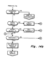
- the emergency relay is a device which receives control signals from a number of points in the system. For example, various protective guards must be in place for operator-safety and, if any one is not in place, a signal goes to the emergency relay to energize it. Had this relay been energized, the "EMERGENCY" message would be presented on the display panel and an exit is made to the "EMERGENCY" routine.
- the Start switch on the local control panel is disabled.
- the microprocessor in the detachable control panel can present command codes zt an appropriate 10 port.
- the "SYNC NO RUN" routine examines this port to detect the presence of command codes and, depending upon which, if any, is detected, any one of several subroutines illustrated on Figures 13(a) and 13(b) may be executed.
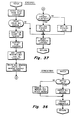
- the "SYNCSTART" subroutine of Figure 36 merely tests the condition of the Infeed switch, and if that switch is on, all motors are energized and the finwheels are engaged, allowing the wrapper to begin moving film past the former and past the cut/seal head in a synchronized fashion. However, if the Infeed switch had not been on, only the cut/seal head motor and the finwheel motors would be engaged and no product would be introduced via the infeed conveyor. This latter mode of operation is generally used during start-up alignment and maintenance.
- an emergency relay will be activated causing the wrapper and its infeed conveyor to immediately shut-down in an unsynchronized manner.
- the MBS causes the instructions comprising the "EMERGENCY" routine to be executed to bring the system back into operation.
- the finwheels and the cut/seal head will again have their temperature controls activated until their desired operating points are reached.
- the RS 232 port on the control panel is examined for the presence of a command code. If no such command code is present, control continues to loop through the various temperature controlling software already described until such time as a command code is presented. That command code is examined to determine its nature, i.e., whether it is a "TSETPUT” command, an "ERRMSG” command, etc. Depending upon the type of command, a different subroutine will be called and executed in response thereto. After the command has been honored, and if the emergency condition has been cleared, the display on the control panel will be made to present the designation "NORUN" and control will exit to the "NORUN" routine previously described.
- the "NORUN" routine includes a series of software operations which, when executed by the computer, causes the functional parts of the wrapper to assume their "HOME" position prior to beginning the normal run condition and, in this fashion, resynchronization is achieved following an emergency shutdown.
- the MBS of the present invention also responds to five types of interrupts, namely, the Eyespot Interrupt, the Missed Eyespot Interrupt, the Pusher Interrupt, The Splicer, Interrupt and the Timeout Interrupt.
- eyespot counter accumulates pulses from the film encoder and, as such, its contents at any time provide an indication of the distance that the film has moved since a preceding eyespot was sensed.
- the contents of that counter accumulated from eyespot-to-eyespot naturally dictates how long the pattern is on the film in question.
- the eyespot-to-eyespot distance may vary over the length of the film as it is played off of its supply roll. This is due to the fact that in the original printing operation on the film during its manufacture when the eyespots are formed, changes in diameter of the feed rolls through the printing apparatus result in a lack of consistency in the eyespot-to-eyespot distance.
- the E YESPOT interrupt routine effectively takes a "snapshot" of the eyespot counter as it counts pulses from the film encoder. A check is made to determine whether the value observed is within a so-called eyespot window, and if it is, that value is saved as the applicable pattern length.
- the eyespot window is arbitrarily defined as being a minimum acceptable distance on either side of an expected eyespot which, if such an eyespot is detected within the range, is recognized by the software as being within tolerance. If an EYESPOT interrupt occurs within the window of the next-expected eyespot, a new window is computed and, as such, figuratively speaking, a sliding window is created in which eyespot testing is to occur.
- the contents of the eyespot counter are fetched and a determination is made as to whether that count value is within or outside of the established window. If it is within the window, that film count value is saved as the "EYECNT" value. The film counter is restarted and then the arbitrarily assigned upper window limit size is added to the "EYECNT" value. Next, the value so computed is sent to the "missing eyespot" counter, the function of which will be discussed when the flow diagram of Figure 38 is considered.
- a test is made to determine whether a first Eyespot flag has been set. This is a flag which, it may be recalled is utilized by the "HOME" subroutine. If it is not found to be set, the next operation is to set that Eyespot flag followed by a resetting of the interrupt latches. Had the test revealed that the first Eyespot flag had been set, then a second Eyespot flag is also set, that, too, being used during the "HOME" subroutine.
- the MISSEDEYESPOT interrupt routine of Figure 38 brings into play the above-mentioned "missing eyespot” counter which has its contents established during the EYESPOT interrupt routine already described. This counter is decremented by one upon the occurrence of each film encoder pulse. Each time an eyespot is found, the "missing eyespot” counter gets reloaded with the upper window value. If the counter should reach zero, then it is known that the expected eyespot either went by undetected or, alternatively, a Splice condition may have resulted in that expected eyespot falling outside of the window zone. When this happens, the MISSEDEYESPOT interrupt occurs. The action resulting from the occurrence of that interrupt is substantially the same as that which results when an EYESPOT interrupt takes place.
- the MISSEDEYESPOT interrupt functions to determine the cut length when unprinted film is used and, also, allows the machine to run until a real eyespot is detected in the window following the occurrence of a Splice.
- the PUSHER interrupt illustrated in Figure 39 merely captures the contents of the counter which is used to accummulate pulses from the infeed conveyor encoder. This value is saved as the "PUSHERCNT" used by certain of the above-described routines. The value in question constitutes the actual infeed flight length.
- the SPLICEREYESPOT interrupt represented by the flow chart of Figure 40 is used to periodically capture the contents of a counter which has been accumulating film encoder pulses and which then acts to reset or restart that counter.
- the signal initiating the SPLICER interrupt is generated by the interaction of an eyespot on the film with the splicer eye 115, which is positioned proximate the splicer station of the wrapper.
- an end-of-film sensor is tripped when the film on a roll is exhausted.
- a splicer solenoid is engergized at a predetermined counter value, which is loaded at the time of the original Setup operation.
- the count value at which the splice is to occur is compared to a current count value and when the equality is reached, the splicer solenoid is activated, causing two rubber rollers to come together so as to press a strip of double-backed adhesive tape to join the tail-end of the exhausted roll to the leading-end of a new roll.
- the main program comprising the CONTROLPANEL routine is illustrated by the flow diagram of Figure 42.
- the remote control panel is structured to comprise a separate, free-standing unit which is adapted to be plugged into a variety of different machines so as to exercise control over those machines.
- the remote control panel 54 includes it own microprocessor controller 59, which is separate and distinct from the microprocessor 51 associated with the wrapper itself.
- the microprocessor in the remote control panel may communicate with the microprocessor of the wrapper via a bi-directional communications link.
- its display/keyboard controller 59 is made to execute the program defined by the flow chart of Figure 42.
- Control Panel which indicates to an operator that the remote control panel is tied into the system and in a position to be utilized.
- certain control lines going to the microprocessor 51 associated with the wrapper and the wrapper microprocessor 51 reacts by transmitting to the remote control panel pertinent information concerning the mode of operation which the wrapper is then in as well as particulars concerning the types of products that are being wrapped.
- the microprocessor in the remo:e control panel is capable of sampling and retrieving the rontents of the memory of the wrapper microprocessor 51.
- the keyboard/display controller 59 when entered, the keyboard/display controller 59 is conditioned to place it in a mode wherein it is able to transmit data over appropriate lines to the common bus leading to the microprocessor 51 in the wrapper.
- a series of test are conducted to determine which, if any, switches on the keyboard have been actuated and, depending upon the particular key number identified, various codes are sent to the wrapper from the remote control panel. For example, if key number C7 (hexidecimal) had been depressed, the so-called "Start" code would be transmitted.
- a code is sent to the wrapper, and the microprocessor in the control panel is configured to receive data from the wrapper.
- the keyboard on the remote control panel is again tested and, if the advance (ADV) key is set, the information received from the wrapper is displayed on the appropriate viewing area on the remote control panel.
- the NORUNGP software when executed by the microprocessor in the remote control panel establishes two-way communication between itself and the microprocessor of the wrapper whereby the wrapper can be controlled from a remote point and whereby information originating at the wrapper can be transmitted to that remote point for display to an operator.
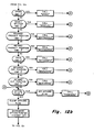
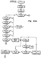
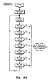
- the subroutine NORMALGP illustrated in Figure 44(a) and Figure 44(b) allows the system to be made to operate in the fashion dictated by the NORMRUN routine of Figures 12 (a) - 12(c) but with the necessary data entries being made at the site of the remote control panel rather than at the local control panel which is a part of the high-speed wrapper itself. Because at this point the reader is familiar with the flow charts presented hereinabove, the diagrams of Figures 44(a) and 44(b) have been simplified by merely indicating that if various ones of the keyboard keys are actuated at the time of sampling, a series of machine operations are executed in accordance with previously described routines and subroutines.
- the subroutine EMSTOPGP also results in calls made to the keyboard 57 to test which keys, if any, have been actuated. Depending upon which key has been actuated, various functions are carried out, all as previously described in connection with the explanation of the NORUNGP subroutine. Because of that previous explanation, no further description of the EMSTOPGP is felt to be necessary.
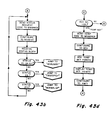
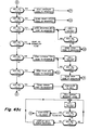
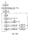
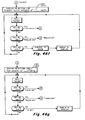
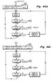
- the final set of software flow diamgrams to be considered are those relating to the SETUP operation which is a function called for during execution of the NORUNGP as shown in Figure 43(a) of the drawings.
- the SETUP subroutine itself is shown in Figures 46(a) through 46(h) of the drawings.
- the SETUP routine presents a series of prompt which help to define the parameters which are necessary to execute the SETUP operation.
Landscapes
- Engineering & Computer Science (AREA)
- Mechanical Engineering (AREA)
- Containers And Plastic Fillers For Packaging (AREA)
Applications Claiming Priority (2)
| Application Number | Priority Date | Filing Date | Title |
|---|---|---|---|
| US06/691,501 US4574566A (en) | 1985-01-14 | 1985-01-14 | Wrapping machine and method |
| US691501 | 1985-01-14 |
Publications (3)
| Publication Number | Publication Date |
|---|---|
| EP0190498A2 true EP0190498A2 (fr) | 1986-08-13 |
| EP0190498A3 EP0190498A3 (en) | 1988-01-20 |
| EP0190498B1 EP0190498B1 (fr) | 1990-07-18 |
Family
ID=24776784
Family Applications (1)
| Application Number | Title | Priority Date | Filing Date |
|---|---|---|---|
| EP85309038A Expired - Lifetime EP0190498B1 (fr) | 1985-01-14 | 1985-12-12 | Machine d'enveloppement |
Country Status (3)
| Country | Link |
|---|---|
| US (1) | US4574566A (fr) |
| EP (1) | EP0190498B1 (fr) |
| DE (1) | DE3578763D1 (fr) |
Cited By (5)
| Publication number | Priority date | Publication date | Assignee | Title |
|---|---|---|---|---|
| GB2204296A (en) * | 1987-05-05 | 1988-11-09 | Sig Schweiz Industrieges | Controlling a packaging machine |
| GB2204551A (en) * | 1987-05-13 | 1988-11-16 | Omori Machinery | Control device for form-fill-seal packaging machine |
| EP0296290A1 (fr) * | 1987-06-25 | 1988-12-28 | Doboy Packaging Machinery, Inc. | Contrôle de produits-hors-registre pour machine d'enveloppement à vitesse élevée |
| GB2176027B (en) * | 1985-05-08 | 1989-06-28 | Fuji Machinery Co | Method and apparatus for controlling a driving system in a packaging machine |
| US7121065B2 (en) | 2003-01-23 | 2006-10-17 | Iwk Verpackungstechnik Gmbh | Method for controlling a blister packaging machine |
Families Citing this family (62)
| Publication number | Priority date | Publication date | Assignee | Title |
|---|---|---|---|---|
| US4712357A (en) * | 1985-10-28 | 1987-12-15 | Fmc Corporation | Computer controlled horizontal wrapper |
| EP0230137B1 (fr) * | 1985-12-24 | 1990-07-18 | Omnitech (Europe) Limited | Machines d'emballage du type "fermer-remplir-sceller" horizontal |
| GB2192503B (en) * | 1986-04-12 | 1990-10-03 | Auto Wrappers | Producing a succession of filled sealed packs |
| US4868759A (en) * | 1986-11-14 | 1989-09-19 | Fmc Corporation | Master position encoder follower system for film feeding means |
| IT1215486B (it) * | 1987-05-13 | 1990-02-14 | Ocme Spa | Apparecchiatura per l'alimentazione di film ed il taglio in fogli dello stesso in una macchina confezionatrice. |
| JPH01267136A (ja) * | 1988-04-07 | 1989-10-25 | Fuji Mach Co Ltd | 包装機の空袋防止制御装置 |
| JPH0520651Y2 (fr) * | 1988-04-26 | 1993-05-28 | ||
| JPH0629049B2 (ja) * | 1988-12-28 | 1994-04-20 | 株式会社フジキカイ | 横型製袋充填包装機のシール体駆動制御装置 |
| DE3902501C2 (de) * | 1989-01-28 | 1996-07-18 | Gorika Giken Co | Verpackungsverfahren |
| US5072575A (en) * | 1989-07-31 | 1991-12-17 | Lakey Lawrence D | Method of feeding articles into a horizontal wrapping machine |
| US5070679A (en) * | 1989-07-31 | 1991-12-10 | Lakey Lawrence D | Horizontal wrapping machine with improved article infeed system |
| US4949846A (en) * | 1989-07-31 | 1990-08-21 | Lakey Lawrence D | Package end sealing and cutting method and apparatus |
| US4967541A (en) * | 1989-07-31 | 1990-11-06 | Lakey Lawrence D | Horizontal wrapping machine with improved article infeed system |
| DE4037097A1 (de) * | 1990-11-22 | 1992-05-27 | Rovema Gmbh | Verfahren zum transport eines endlosen kunststoff-schlauches |
| US5138815A (en) * | 1991-11-12 | 1992-08-18 | Doboy Packaging Machinery, Inc. | Microprocessor controlled SCR motor drives for wrapping machine |
| IT1250241B (it) * | 1991-12-04 | 1995-04-03 | Cavanna Spa | Macchina confezionatrice,particolarmente per la formazione di involucri del tipo flow-pack e simili e relativo procedimento di azionamento |
| US5359832A (en) * | 1992-09-04 | 1994-11-01 | Cloud Corporation | Accumulator and collator for packaging apparatus |
| IT1272415B (it) * | 1993-04-28 | 1997-06-23 | Otem Officina Tecnomeccanica E | Dispositivo per la movimentazione di una pellicola per l'impacchettamento |
| NL9400550A (nl) * | 1994-04-07 | 1995-11-01 | Kloeckner Haensel Tevopharm | Flowpacker en beitelsamenstel daarvoor. |
| JP2801530B2 (ja) * | 1994-08-17 | 1998-09-21 | 株式会社フジキカイ | 横型製袋充填包装機及びその制御方法 |
| US5584166A (en) * | 1994-11-10 | 1996-12-17 | Lakey; Lawrence D. | Flexible package end sealing and cutting method and apparatus |
| US5566526A (en) * | 1995-08-25 | 1996-10-22 | Ibaraki Seiki Machinery Company, Ltd. | Device motor controlling apparatus for use in packaging machine |
| US5666788A (en) * | 1996-04-16 | 1997-09-16 | Ossid Corporation | Method for transverse sealing of film wrapped around a product |
| US5871783A (en) * | 1996-08-22 | 1999-02-16 | Mars, Incorporated | Apparatus for ultrasonically forming confectionery products |
| US5861185A (en) * | 1996-08-22 | 1999-01-19 | Mars, Incorporated | Ultrasonic forming of confectionery products |
| US5871793A (en) | 1996-11-27 | 1999-02-16 | Mars Incorporated | Puffed cereal cakes |
| US5752365A (en) * | 1996-12-09 | 1998-05-19 | General Mills, Inc. | Apparatus and methods for inserting premium items |
| DE19803838C2 (de) * | 1997-02-05 | 2000-05-25 | Rovema Gmbh | Verwendung eines Verfahrens zum Betreiben einer Schlauchbeutelmaschine zur Erkennung eines Produkteinschlusses |
| US5775065A (en) * | 1997-05-01 | 1998-07-07 | Ossid Corporation | Method and apparatus for transverse cutting and sealing film wrapped around a product |
| FI103958B (fi) * | 1998-04-01 | 1999-10-29 | Valmet Corp | Menetelmä ja sovitelma kääreradan pään viemiseksi vetotelojen nippiin rullankäärintälaitteessa |
| JP4229221B2 (ja) * | 1998-05-18 | 2009-02-25 | 株式会社イシダ | 包装装置 |
| US20020127310A1 (en) * | 1998-12-07 | 2002-09-12 | Capodieci Roberto A. | Cereal food product and method |
| US6368647B1 (en) * | 1998-12-29 | 2002-04-09 | Mars, Incorporated | Ultrasonically activated continuous slitter apparatus and method |
| US6484475B1 (en) * | 1999-02-02 | 2002-11-26 | Kisters Kayat, Inc. | Modular packaging machine |
| US6574944B2 (en) * | 2001-06-19 | 2003-06-10 | Mars Incorporated | Method and system for ultrasonic sealing of food product packaging |
| US6655948B2 (en) | 2001-08-31 | 2003-12-02 | Mars, Incorporated | System of ultrasonic processing of pre-baked food product |
| US6635292B2 (en) | 2001-10-26 | 2003-10-21 | Mars, Incorporated | Ultrasonic rotary forming of food products |
| US6869386B2 (en) * | 2002-06-26 | 2005-03-22 | The Procter & Gamble Company | Method for manufacturing discrete articles from a material web using synchronized servo-actuated operational units |
| DE10261256B4 (de) * | 2002-12-20 | 2004-11-11 | Windmöller & Hölscher Kg | Bodenlegevorrichtung |
| US7131249B2 (en) * | 2003-11-13 | 2006-11-07 | Steinmetz Machine Works, Inc. | Product overwrap machine |
| US7302781B2 (en) * | 2004-09-21 | 2007-12-04 | C.G. Bretting Manufacturing Company, Inc. | Bander apparatus and method of using same |
| US7281362B2 (en) * | 2004-11-22 | 2007-10-16 | Shrink Packaging Systems Corporation | Film side sealing apparatus with closed-loop temperature control of a heater |
| ITMO20080063A1 (it) * | 2008-03-05 | 2009-09-06 | Inovapak Srl | Apparati e metodi per produrre contenitori |
| US20100310731A1 (en) * | 2009-06-03 | 2010-12-09 | Kraft Foods Global Brands Llc | Method and apparatus to wrap a plastic container |
| WO2013092081A1 (fr) | 2011-12-21 | 2013-06-27 | Unilever N.V. | Emballage contenant un cube de matière ou une tablette de matière |
| US9030148B2 (en) * | 2013-03-14 | 2015-05-12 | Regal Beloit America, Inc. | Systems and methods for controlling electric motors |
| EP2818421A1 (fr) * | 2013-06-25 | 2014-12-31 | Multivac Sepp Haggenmüller GmbH & Co. KG | Machine de fermeture de barquettes avec une alimentation de barquettes et procédé pour une installation d'emballage |
| US10287046B2 (en) * | 2014-10-28 | 2019-05-14 | Omron Corporation | Control apparatus, system, and program library |
| WO2016179204A1 (fr) * | 2015-05-05 | 2016-11-10 | Sealed Air Corporation (Us) | Système d'emballage |
| CN106142802B (zh) * | 2016-07-21 | 2018-03-27 | 无锡市博宇塑机有限公司 | Pvc彩膜同步对花系统及其控制方法 |
| WO2018039385A1 (fr) * | 2016-08-23 | 2018-03-01 | Automated Solotions, Llc | Systèmes de formation d'emballages et procédés associés |
| JP6583341B2 (ja) * | 2017-04-14 | 2019-10-02 | オムロン株式会社 | 包装機、包装機のための制御装置、制御方法、およびプログラム |
| JP7071729B2 (ja) * | 2017-11-01 | 2022-05-19 | 株式会社イシダ | 製袋包装機 |
| DE102017131417A1 (de) * | 2017-12-29 | 2019-07-04 | Weber Maschinenbau Gmbh Breidenbach | Vorrichtung zum Verpacken von Objekten |
| US11110666B2 (en) | 2018-02-12 | 2021-09-07 | Tipper Tie, Inc. | Systems with external heat-seal assembly height adjustment control and related seal assemblies |
| CN109353596A (zh) * | 2018-11-01 | 2019-02-19 | 青岛海科佳电子设备制造有限公司 | 宽度可调包装袋成型器、制袋器、包装机及方法 |
| EP3932811B8 (fr) * | 2020-06-29 | 2022-07-20 | Ulma Packaging, S.Coop. | Machine d'emballage horizontale |
| WO2022171856A1 (fr) * | 2021-02-15 | 2022-08-18 | Tetra Laval Holdings & Finance S.A. | Procédé d'évaluation de la qualité de scellement transversal d'un emballage alimentaire |
| DE102021112794B4 (de) | 2021-05-18 | 2023-12-21 | Rovema Gmbh | Verfahren zum Betrieb einer Schlauchbeutelmaschine |
| ES3037788T3 (en) * | 2021-10-15 | 2025-10-06 | Multivac Haggenmueller Kg | A sealing machine and a method for sealing a sealing material |
| CN115489805B (zh) * | 2022-11-21 | 2023-04-07 | 佛山市奥尔格机械设备有限公司 | 用于水溶性包装膜的枕式包装机 |
| US20250382081A1 (en) * | 2024-06-14 | 2025-12-18 | The Procter & Gamble Company | Polymer film envelope package for compact feminine hygiene pad product, and process and tooling for manufacture thereof |
Family Cites Families (13)
| Publication number | Priority date | Publication date | Assignee | Title |
|---|---|---|---|---|
| CH374587A (de) * | 1959-08-31 | 1964-01-15 | Sig Schweiz Industrieges | Vorrichtung zum kontinuierlichen Herstellen von Packungen |
| US3445981A (en) * | 1966-07-29 | 1969-05-27 | Gates Rubber Co | Method and means for forming a seed tape |
| US3552088A (en) * | 1968-07-18 | 1971-01-05 | Nishimura Seisakusho Co | Method of and apparatus for packing articles |
| US3958390A (en) * | 1975-01-02 | 1976-05-25 | Hayssen Manufacturing Co. | Packaging |
| US4106265A (en) * | 1975-05-29 | 1978-08-15 | Fmc Corporation | Wrapping machine and method with four side rotary tucker |
| DE2626448A1 (de) * | 1976-06-12 | 1977-12-22 | Agfa Gevaert Ag | Anordnung zur abfertigung von kopierauftraegen |
| DE2706676C2 (de) * | 1977-02-17 | 1979-03-08 | Bielomatik Leuze & Co, 7442 Neuffen | Verpackungsmaschine mit einer Formschulter zur Umformung einer Folienbahn zu einem Schlauch |
| DK144555C (da) * | 1978-10-26 | 1982-11-01 | Gram Broedrene A S | Fremgangsmaade til brug ved emballering af genstande i et antal emballagematerialebaner og apparat til brug ved udoevelse affremgangsmaaden |
| IT1112724B (it) * | 1979-04-24 | 1986-01-20 | Sitma Soc Italiana Macchine Au | Dispositivo per controllare la posizione della pellicola rispetto ai prodotti da imballare in una macchina da imballaggio impiegante una pellicola stampata |
| US4316566A (en) * | 1980-07-17 | 1982-02-23 | R. A. Jones & Co. Inc. | Apparatus for registration and control for a moving web |
| IT1154404B (it) * | 1982-01-05 | 1987-01-21 | Alisyncro Srl | Sistema e metodo per asservire un primo motore elettrico ad un secondo motore elettrico e macchina incartatrice utilizzante tale sistema |
| GB2138381B (en) * | 1983-04-18 | 1987-09-30 | Baker Perkins Holdings Plc | Form-fill-seal wrapping apparatus |
| US4506488A (en) * | 1983-05-13 | 1985-03-26 | Doboy Packaging Machinery, Inc. | Wrapping machine and method |
-
1985
- 1985-01-14 US US06/691,501 patent/US4574566A/en not_active Expired - Lifetime
- 1985-12-12 EP EP85309038A patent/EP0190498B1/fr not_active Expired - Lifetime
- 1985-12-12 DE DE8585309038T patent/DE3578763D1/de not_active Expired - Lifetime
Cited By (6)
| Publication number | Priority date | Publication date | Assignee | Title |
|---|---|---|---|---|
| GB2176027B (en) * | 1985-05-08 | 1989-06-28 | Fuji Machinery Co | Method and apparatus for controlling a driving system in a packaging machine |
| GB2204296A (en) * | 1987-05-05 | 1988-11-09 | Sig Schweiz Industrieges | Controlling a packaging machine |
| GB2204296B (en) * | 1987-05-05 | 1991-06-12 | Sig Schweiz Industrieges | Controlling a packaging machine |
| GB2204551A (en) * | 1987-05-13 | 1988-11-16 | Omori Machinery | Control device for form-fill-seal packaging machine |
| EP0296290A1 (fr) * | 1987-06-25 | 1988-12-28 | Doboy Packaging Machinery, Inc. | Contrôle de produits-hors-registre pour machine d'enveloppement à vitesse élevée |
| US7121065B2 (en) | 2003-01-23 | 2006-10-17 | Iwk Verpackungstechnik Gmbh | Method for controlling a blister packaging machine |
Also Published As
| Publication number | Publication date |
|---|---|
| EP0190498A3 (en) | 1988-01-20 |
| DE3578763D1 (de) | 1990-08-23 |
| EP0190498B1 (fr) | 1990-07-18 |
| US4574566A (en) | 1986-03-11 |
Similar Documents
| Publication | Publication Date | Title |
|---|---|---|
| US4574566A (en) | Wrapping machine and method | |
| US4506488A (en) | Wrapping machine and method | |
| US4525977A (en) | Wrapping machine and method | |
| US4722168A (en) | Product-out-of-registration control for high speed wrapping machine | |
| US4549386A (en) | Form-fill-seal wrapping apparatus | |
| EP0542393B1 (fr) | SCR-moteur d'entraînement contrÔlé par microprocesseur pour machine d'emballage | |
| US4909018A (en) | Control device and method for controlling the driving system of a packaging machine | |
| US4067760A (en) | Gate control for printed web scanner | |
| US4848630A (en) | Method and apparatus for positioning a web of material in stepwise transporation thereof | |
| CA1158747A (fr) | Dispositif d'alignement et d'avance pour feuille en defilement | |
| US5347791A (en) | Computer controlled horizontal wrapper | |
| US4248655A (en) | Position control system for a moving web | |
| GB2176027A (en) | Method and apparatus for controlling a driving system in a packaging machine | |
| GB2183366A (en) | Computer controlled horizontal wrapping machine | |
| EP0375857A1 (fr) | Procédé et appareil d'emballage | |
| GB2138381A (en) | Form-fill-seal wrapping apparatus | |
| GB2088100A (en) | Control of cutoff apparatus | |
| EP0759358B1 (fr) | Correction des bandes avancées pas à pas en registre | |
| JPS61183045A (ja) | 包装用紙供給装置の切換装置 | |
| EP0174161A2 (fr) | Machine d'enveloppement | |
| JPS6222847B2 (fr) | ||
| JPS63138906A (ja) | 物品包装装置 | |
| US4894976A (en) | Missing card circuit for a slicing machine | |
| US4545174A (en) | Timing adjusting device for packaging machines | |
| EP0084698B1 (fr) | Appareil et méthode pour varier l'emplacement d'une opération effectuée sur un élément allongé mobile |
Legal Events
| Date | Code | Title | Description |
|---|---|---|---|
| PUAI | Public reference made under article 153(3) epc to a published international application that has entered the european phase |
Free format text: ORIGINAL CODE: 0009012 |
|
| AK | Designated contracting states |
Kind code of ref document: A2 Designated state(s): CH DE GB IT LI NL |
|
| PUAL | Search report despatched |
Free format text: ORIGINAL CODE: 0009013 |
|
| AK | Designated contracting states |
Kind code of ref document: A3 Designated state(s): CH DE GB IT LI NL |
|
| 17P | Request for examination filed |
Effective date: 19880402 |
|
| 17Q | First examination report despatched |
Effective date: 19890208 |
|
| GRAA | (expected) grant |
Free format text: ORIGINAL CODE: 0009210 |
|
| RAP1 | Party data changed (applicant data changed or rights of an application transferred) |
Owner name: DOBOY PACKAGING MACHINERY, INC. |
|
| AK | Designated contracting states |
Kind code of ref document: B1 Designated state(s): CH DE GB IT LI NL |
|
| REF | Corresponds to: |
Ref document number: 3578763 Country of ref document: DE Date of ref document: 19900823 |
|
| ITF | It: translation for a ep patent filed | ||
| ITTA | It: last paid annual fee | ||
| PLBE | No opposition filed within time limit |
Free format text: ORIGINAL CODE: 0009261 |
|
| STAA | Information on the status of an ep patent application or granted ep patent |
Free format text: STATUS: NO OPPOSITION FILED WITHIN TIME LIMIT |
|
| 26N | No opposition filed | ||
| PGFP | Annual fee paid to national office [announced via postgrant information from national office to epo] |
Ref country code: GB Payment date: 19971203 Year of fee payment: 13 |
|
| PGFP | Annual fee paid to national office [announced via postgrant information from national office to epo] |
Ref country code: DE Payment date: 19971222 Year of fee payment: 13 |
|
| PGFP | Annual fee paid to national office [announced via postgrant information from national office to epo] |
Ref country code: NL Payment date: 19971223 Year of fee payment: 13 |
|
| PGFP | Annual fee paid to national office [announced via postgrant information from national office to epo] |
Ref country code: CH Payment date: 19980107 Year of fee payment: 13 |
|
| PG25 | Lapsed in a contracting state [announced via postgrant information from national office to epo] |
Ref country code: GB Free format text: LAPSE BECAUSE OF NON-PAYMENT OF DUE FEES Effective date: 19981212 |
|
| PG25 | Lapsed in a contracting state [announced via postgrant information from national office to epo] |
Ref country code: LI Free format text: LAPSE BECAUSE OF NON-PAYMENT OF DUE FEES Effective date: 19981231 Ref country code: CH Free format text: LAPSE BECAUSE OF NON-PAYMENT OF DUE FEES Effective date: 19981231 |
|
| PG25 | Lapsed in a contracting state [announced via postgrant information from national office to epo] |
Ref country code: NL Free format text: LAPSE BECAUSE OF NON-PAYMENT OF DUE FEES Effective date: 19990701 |
|
| GBPC | Gb: european patent ceased through non-payment of renewal fee |
Effective date: 19981212 |
|
| REG | Reference to a national code |
Ref country code: CH Ref legal event code: PL |
|
| NLV4 | Nl: lapsed or anulled due to non-payment of the annual fee |
Effective date: 19990701 |
|
| PG25 | Lapsed in a contracting state [announced via postgrant information from national office to epo] |
Ref country code: DE Free format text: LAPSE BECAUSE OF NON-PAYMENT OF DUE FEES Effective date: 19991001 |