EP0191295A2 - Vorrichtung zum Anbringen von Kabeln an Tragseilen - Google Patents
Vorrichtung zum Anbringen von Kabeln an Tragseilen Download PDFInfo
- Publication number
- EP0191295A2 EP0191295A2 EP86100245A EP86100245A EP0191295A2 EP 0191295 A2 EP0191295 A2 EP 0191295A2 EP 86100245 A EP86100245 A EP 86100245A EP 86100245 A EP86100245 A EP 86100245A EP 0191295 A2 EP0191295 A2 EP 0191295A2
- Authority
- EP
- European Patent Office
- Prior art keywords
- cable
- feed module
- folding
- suspension
- attachment elements
- Prior art date
- Legal status (The legal status is an assumption and is not a legal conclusion. Google has not performed a legal analysis and makes no representation as to the accuracy of the status listed.)
- Withdrawn
Links
- 239000000725 suspension Substances 0.000 claims abstract description 44
- 230000007246 mechanism Effects 0.000 claims abstract description 13
- 238000005452 bending Methods 0.000 claims description 9
- 238000003860 storage Methods 0.000 claims description 7
- 238000010008 shearing Methods 0.000 claims description 4
- 230000001427 coherent effect Effects 0.000 claims description 3
- 230000004913 activation Effects 0.000 claims description 2
- 238000005461 lubrication Methods 0.000 claims description 2
- 230000001360 synchronised effect Effects 0.000 claims description 2
- 230000015572 biosynthetic process Effects 0.000 claims 1
- 238000004049 embossing Methods 0.000 claims 1
- 238000005755 formation reaction Methods 0.000 claims 1
- 230000005540 biological transmission Effects 0.000 abstract description 7
- 238000000034 method Methods 0.000 description 9
- 230000033001 locomotion Effects 0.000 description 3
- 238000003825 pressing Methods 0.000 description 3
- 238000005520 cutting process Methods 0.000 description 2
- 239000000314 lubricant Substances 0.000 description 2
- 239000000463 material Substances 0.000 description 2
- 229910000831 Steel Inorganic materials 0.000 description 1
- 230000004308 accommodation Effects 0.000 description 1
- 230000006978 adaptation Effects 0.000 description 1
- 238000002788 crimping Methods 0.000 description 1
- 238000009434 installation Methods 0.000 description 1
- 210000002445 nipple Anatomy 0.000 description 1
- 238000000926 separation method Methods 0.000 description 1
- 239000010959 steel Substances 0.000 description 1
- 230000008961 swelling Effects 0.000 description 1
Images


Classifications
-
- H—ELECTRICITY
- H02—GENERATION; CONVERSION OR DISTRIBUTION OF ELECTRIC POWER
- H02G—INSTALLATION OF ELECTRIC CABLES OR LINES, OR OF COMBINED OPTICAL AND ELECTRIC CABLES OR LINES
- H02G1/00—Methods or apparatus specially adapted for installing, maintaining, repairing or dismantling electric cables or lines
- H02G1/02—Methods or apparatus specially adapted for installing, maintaining, repairing or dismantling electric cables or lines for overhead lines or cables
-
- Y—GENERAL TAGGING OF NEW TECHNOLOGICAL DEVELOPMENTS; GENERAL TAGGING OF CROSS-SECTIONAL TECHNOLOGIES SPANNING OVER SEVERAL SECTIONS OF THE IPC; TECHNICAL SUBJECTS COVERED BY FORMER USPC CROSS-REFERENCE ART COLLECTIONS [XRACs] AND DIGESTS
- Y10—TECHNICAL SUBJECTS COVERED BY FORMER USPC
- Y10T—TECHNICAL SUBJECTS COVERED BY FORMER US CLASSIFICATION
- Y10T29/00—Metal working
- Y10T29/51—Plural diverse manufacturing apparatus including means for metal shaping or assembling
- Y10T29/5136—Separate tool stations for selective or successive operation on work
- Y10T29/5137—Separate tool stations for selective or successive operation on work including assembling or disassembling station
- Y10T29/5143—Separate tool stations for selective or successive operation on work including assembling or disassembling station and means to machine product
-
- Y—GENERAL TAGGING OF NEW TECHNOLOGICAL DEVELOPMENTS; GENERAL TAGGING OF CROSS-SECTIONAL TECHNOLOGIES SPANNING OVER SEVERAL SECTIONS OF THE IPC; TECHNICAL SUBJECTS COVERED BY FORMER USPC CROSS-REFERENCE ART COLLECTIONS [XRACs] AND DIGESTS
- Y10—TECHNICAL SUBJECTS COVERED BY FORMER USPC
- Y10T—TECHNICAL SUBJECTS COVERED BY FORMER US CLASSIFICATION
- Y10T29/00—Metal working
- Y10T29/51—Plural diverse manufacturing apparatus including means for metal shaping or assembling
- Y10T29/5191—Assembly
Definitions
- the invention relates to a device for attaching cables to suspension ropes, the device which can be moved along the suspension rope carrying a storage container with fastening means which can be separated from one another and which, by means of a folding device made of stamping rollers arranged on both sides of the suspension rope, on the combination to be connected to one another Carrier cable / cable can be stamped, with the fastening means initially being joined together in the form of a band and separable into individual fastening elements by a separating device which is arranged in a feed module for the fastening means.
- a device of the aforementioned type is known from DE-OS 32 28 227.
- a guide channel is formed by guide and pressure rollers, a triggering device for the fastening means being arranged above the carrying cable inserted into the device.
- the fastening means are closed below the suspension cable / cable combination to be connected to one another. So all other devices required for folding are arranged below the suspension cable.
- the folding device is arranged above the supporting rope, that the folding device has a wedge-shaped inlet for the attachment elements, that the feed module in the separating device has a shearing mechanism with several chisels and a counter-roller designed as an abutment, that the feed module is arranged below the cable to be fastened, that the feed module can be unlocked, that a coupled double belt drive for the feed module is arranged in a force-fitting manner on both sides of the suspension cable, that a lifting device for the attachment elements at the exit of the Feed module is arranged, and that a suspension device is arranged.
- An advantage of the device according to the invention is, for example, that it can first be easily attached to the suspension cable and only then is it activated by switching on the drive.
- the drive itself and the workflow controlled by it in the individual mechanisms only starts when the device is pulled along the suspension cable. This is done, for example, by a pull rope from the ground.
- the movement of the device could also be controlled wirelessly if a remotely controllable drive is provided.
- the drive can also be released as required, so that the device can run freely at any time. This measure is particularly important when the device has to be pulled back, for example at a patch or connection point on the suspension cable.
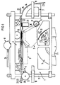
- the storage container 5 for fasteners 19, the feed module 2, the double belt drive 3, the folding device 4, the suspension devices 6 and the release mechanism 8 are arranged functionally in a support frame. Furthermore, the guidance of the support cable 22 and the cable 23 to be attached to it, as well as the partial guidance of the fastening means 19 from the storage container 5 into the feed module 2 can be seen. It can be seen from this that the suspension cable 22, as well as the cable 23, are guided above the feed module 2 and the double belt drive 3, the suspension devices 6 for applying the entire device 1 to the suspension cable 22 being arranged at the beginning and at the end of the device 1 .
- the device 1 is aligned with these suspension aids 6 so that it hangs with its support rollers 11 on the support rope 22 and can thus be moved hanging. Furthermore, in this case, an auxiliary drive roller 10 with a relatively large diameter is arranged in addition to the double belt drive 3, which is mechanically coupled to it via a transmission, so that additional power transmission is achieved.
- the band-shaped connected fastening means 19 fed from the storage container 5 are guided, divided into individual attachment elements 20 and finally passed on to the double belt drive 3. The details are explained in more detail with the aid of detailed figures.
- the feed module 2 can also be activated by a connection mechanism 9 with the aid of a corresponding lever mechanism 16 and possibly with the aid of a controlled motor 17, so that the device as a whole can be pulled along the suspension cable 22 in a "free-running" manner.
- the feeding of the fastening elements 19 which are still wound in a band shape on a drum core are evenly removed from the core 25, which has the profile of the attachment elements 20, via a polygonal disc 21, which rotates in a manner synchronized with the sequence in the feed module 2.
- the longitudinal edges of the disk 21 each correspond to the length of the attachment elements 20 used.
- the cable 23 to be attached to the support cable 22 is fed via the cable feed device 7.
- This cable feed device 7 contains a plurality of cable guides 15, which are arranged on a curved frame 14 and form a groove in which the cable 23 is guided. These cable guides 15 are angular, so that they serve at the same time as dirt wiping for the cable 23.
- the curvature of the frame 14 is selected so that the cable 23 is not bent more than permissible during the feeding, so that there is a perfect protection against kinking or bending. From this figure it can further be seen that after the suspension cable 22 and cable 23 have been merged, the combination suspension cable / cable 22-23 passes through the double belt drive 3, which drives the mechanisms, and the folding device 4 arranged above for the attachment elements 20 and leaves the device at the end with the attachment elements 20, clamped together.
- a guide roller 12 at the end ensures safe locomotion, particularly when the device is returning.
- the unlocking device 8 which is mechanically actuated via a lever 24, the device can be lowered fully functional onto the suspension rope 22 after hanging on the suspension rope 22 with the suspension auxiliary devices 6, while at the same time the frictional contact between the suspension rope 22 and the drive mechanisms is guaranteed.
- a transmission 26 is indicated, which is known per se and via which the synchronization of the two belt drives and the roller 10 takes place.
- This double belt drive 3 essentially consists of two individual belts 27 which are guided on both sides of the support cable 22 in grooves 49 (FIG. 6) by a plurality of guide rollers 28 arranged one behind the other along the support cable 22 when the device 1 is switched on in a force-locking manner.
- the belts 27 are moved as a result of the friction to the support cable 22, the required power transmission being carried out by deflecting the belts via the roller 29 to the feed module and via the rollers 65 to the transmission 26 or the downstream mechanisms .
- FIG. 3 now illustrates the individual attachment elements 20 that are used in the device in one Cross-sectional view in the upper region of the figure and in a plan view of these attachment elements 20, which are combined as a band-shaped fastening means 19, as can be seen from the lower part of the figure.
- the combination of the suspension cable / cable is sunk into the arcuate part of the attachment element 20 with the aid of the device, or the attachment element 20 is raised from below by the feed module 2 to the combination of the suspension cable / cable 22-23.
- the ends 20a, 20b and 20c of the attachment element 20 are already pre-bent in such a way that a simple fold can be produced in the device by simple folding means.
- the individual attachment elements 20 can be supplied in an efficient manner, they are chained together via narrow webs 33 and finally drummed up in a storage container from which they are removed.
- the band-shaped fastening means 19 are separated into individual attachment elements 20 in the feed module 2, as will be explained in more detail in the following figure.
- a hole 32 is provided in each attachment element 20, into which a synchronizing pin 36 is then inserted.
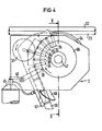
- FIG. 4 shows the feed module 2 in detail.
- This feed module 2 essentially consists of a disk-shaped carrier body 66 on the outer circumference of which the separating tools are arranged in the form of chisels 35 and are evenly distributed.
- these chisels 35 serve to cut off by shearing and not by cutting. This means that the service life of the cutting tools is significantly increased.
- an abutment is required to shear off an object and this abutment is made of hard material by a stepwise rotating disk 37 Material, for example made of steel.
- the distance between the chisel tip and the surface of the abutment is chosen so that it can be sheared properly.
- the attachment elements 20 are pushed in a coherent manner out of the storage container, whereby they are continued in an adapted mold gap within the feed module 2.
- This shaped gap is formed by a shaped piece 67 adapted to the inner shape of the attachment element 20 and an outer shaped sheet 68.
- Synchronizing pins 36 which are each arranged between the chisels 35 on the circumference of the disk-shaped carrier body 66, preferably in divisions of twelve, serve for the right time of the separation.
- the chisels 35 which each have a V-shaped shape on the outside, also take care of the advancement of the attachment elements 20, which reach behind the attachment elements 20 and convey them one step further as the rotation progresses.
- a lubrication device 41 is controlled from the disk 66 via nipples 39, which exerts a brief pressure on a lubricant container 41 after each revolution and thereby deposits a corresponding proportion of lubricant at the required points, for example in the mold gap.
- the separated An is transferred clamp element 20 to the - not shown here - double belt drive, through which it is continued in the folding device.
- the combination of the suspension cable / cable 22-23 to be connected is indicated for orientation.
- the section line for the following FIG. 5 is characterized by the section V-V.
- FIG. 5 illustrates with a section through the drum 66 of the feed module 2 the structure of the lifting device for the attachment elements 20, which is mounted in the drum 66, after they have been separated from the coherent band.
- the attachment elements 20 are guided through the synchronizing pins 36 up to the elevation, these being arranged in each case in a bore in the individual levers 44 of the lifting device.
- the levers 44 are now rotatably mounted parallel to the axis 42 of the drum 66 on the outer circumference with a hinge 4.5 at one end. The other ends of the levers 44 each dip into a deflection groove 43 of a deflection disk 34 arranged parallel to the drum 66.
- This deflection groove 43 is in principle introduced in a circle into the deflection disk 34; however, it has a deflection toward the edge at the deflection point for the attachment elements 20, so that the levers 44 are deflected outward following the movement of their guided ends.
- the result of this is that the attachment element 20 located above the deflected lever 44 is raised to the combination of the carrying cable / cable 22-23 and then at the same time taken over by the belt 27 - not shown here - of the double belt drive 3 and transported further .
- the lever 44 is guided in the retracted state due to the deflection groove 43 and that the synchronizing pin 36 is exposed for the new accommodation of an attachment element 20.
- FIG. 6 shows, with a cross section through the double belt drive 3 in the area of the takeover of a fastening element 20, the guidance of the combination of the carrying rope / cable 22-23, which is pressed in the lower part of the double belt drive 3 against the V-belt 48, which is guided in a system of several identical rollers 47 , so that a clear location is fixed.
- the combination of the suspension cable / cable 22-23 is, however, also guided non-positively between the belts 27 of the double drive 3.
- the drive for the individual mechanisms takes place through the frictional connection.
- the attachment element 20 taken over by the two belts 27 has already been introduced in the correct position for attachment to the combination of the carrying cable / cable 22-23.
- the belts 27 are guided in this area in grooves 49 of the rollers 28, the axes 46 of which are inclined in accordance with the diameter ratio of the suspension cable 22 and the cable 23 in order to achieve an optimal adaptation and thus also power transmission.
- the double belt drive 3 is preferably interchangeable, so that the unit adapted to the diameter ratio can be used in each case.
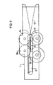
- FIG. 7 shows a top view of the folding device 4, which interacts with the previously described unit of the double belt drive 3.
- the bellows element 20, which is taken over in the double belt drive 3, as can be clearly seen in FIG. 5, is brought together during further transport into the folding device 4 by the wedge-shaped inlet 53 at the upper still open ends 20a and 20b and thus for the pressing process, which is caused by the first pinch roller pair 54 is executed, prepared.
- the attachment element 20 passes into the slot groove 60 of a folding roller 55, the longer, protruding free end of the attachment element 20 being folded back here.
- the fold which has already been formed is bent laterally by a pair of bending rollers 56 and is thus prepared for the final pressing of the fold by a folding roller 57.
- a swelling process is ended and the process begins again for the next one at the selected distance Swell process.
- Figure 8 shows a schematic representation of the pressing of the two ends 20a and 20b by the two pressure rollers 54, which are mounted with their axes 58 perpendicular to the running direction of the suspension cable. For the sake of clarity, all further details are not shown in this and the following illustrations. However, it can be seen here that the longer end 20c of the attachment element 20 still protrudes perpendicularly from the two ends 20a and 20b which have already been compressed.
- FIG. 9 it is indicated how the end 20c of the attachment element 20 which still protrudes vertically in the previous process is folded back over the first end 20a with a folding roller 55 which has a circumferential slot groove 60.
- the attachment element 20 enters the slot groove 60, the free end 20c undergoes a deflection as a result of the rounded flank 61 and finally the crimping onto the ends 20a and 20b which have already been compressed.
- the rounded edge 61 lies thereby on the side of the still protruding end 20c.
- FIG. 10 shows the following process, namely the lateral bending of the already formed fold 62 into an inclined position with the aid of two bending rollers 56 and 56a, the axes 63 of which are arranged perpendicular to the axis 59 of the folding roller 55.
- the edges of the bending rollers 56 and 56a are beveled in opposite directions, so that an obliquely running gap is formed between them, into which the fold 62 runs.
- the two axes 63 are slightly offset from one another, so that the bending roller 56a, the edge of which is wider at the top than at the bottom, first contacts the fold 62 and bends it laterally.
- the fold 62 is further deformed and pressed together in the oblique gap between the two bending rollers 56 and 56a.
- FIG. 11 finally shows the last process in which the fold 62 is pressed by a folding roller 57, the axis 64 of which again runs perpendicular to the axes 63 of the bending rollers 56.
- This folding roller 57 has a pitch circle groove 67 on the circumference. The height of this pitch circle groove 67 is matched to the combination of the carrying cable / cable 22-23 with its attachment element 20 in such a way that the fold 62 is pressed completely down.
- the Anschellvorgang is completed and the combination of carrier cable / cable 22 - 23 leaves in RGBgeschellten state over a final guide roller 12 across the device.
- FIG. 12 finally shows the auxiliary suspension device 6, with the aid of which the device 1 is simply suspended on the suspension cable 22 before the start of the attachment.
- This suspension auxiliary device 6, two of which are arranged in the device 1, consists of a bracket 50 firmly anchored to the device 1, which hooks at both ends 51 and 52 is bent out in a shape.
- the end 51 is preferably designed as a catch hook, while the hook shape of the second end 52 corresponds approximately to the shape, that is to say the diameter, of the support cable 22.
- the position of the end 52 also coincides with the position of the support cable 22 with respect to the further process, except in terms of height.
Landscapes
- Processing Of Terminals (AREA)
- Electric Cable Installation (AREA)
- Folding Of Thin Sheet-Like Materials, Special Discharging Devices, And Others (AREA)
Abstract
Description
- Die Erfindung betrifft eine Vorrichtung zum Anbringen von Kabeln an Tragseilen, wobei die entlang des Tragseils verfahrbare Vorrichtung einen Vorratsbehälter mit Befestigungsmitteln mitführt, die im Abstand voneinander absetzbar sind und die durch eine Falzvorrichtung aus zu beiden Seiten des Tragseils angeordneten Prägerollen an die miteinander zu verbindende Kombination Tragseil/Kabel anprägbar sind, wobei weiterhin die Befestigungsmittel zunächst bandförmig aneinandergefügt und durch eine Trennvorrichtung, die in einem Zuführungsmodul für die Befestigungsmittel angeordnet ist, in einzelne Anschellelemente teilbar sind.
- Eine Vorrichtung der vorgenannten Art ist aus der DE-OS 32 28 227 bekannt. Dort wird durch Führungs- und Andruckrollen ein Führungskanal gebildet, wobei eine Auslösevorrichtung für die Befestigungsmittel oberhalb des in die Vorrichtung eingeführten Tragseiles angeordnet ist. Daraus ergibt sich, daß der Verschluß der Befestigungsmittel unterhalb der miteinander zu verbindenden Kombination Tragseil/Kabel erfolgt. So sind auch alle weiteren für das Falzen erforderlichen Vorrichtungen unterhalb des Tragseils angeordnet.
- Für vorliegende Erfindung ergibt sich nun die Aufgabe, eine Vorrichtung zum Anbringen von Kabeln an Tragseilen zu schaffen, mit der ein sicherer Antrieb aller erforderlichen Einzelvorrichtungen gewährleistet ist, wobei neben einfacher Handhabung des Geräts auch eine entsprechend lange Lebensdauer der Verschleißteile, insbesondere des Abtrennmechanismus für die Befestigungsmittel, gewährleistet werden muß. Die gestellte Aufgabe wird nun gemäß der Erfindung mit einer Vorrichtung der eingangs erläuterten Art dadurch gelöst, daß die Falzvorrichtung oberhalb des Tragseils angeordnet ist, daß die Falzvorrichtung einen keilförmigen Einlauf für die Anschellelemente aufweist, daß das Zuführungsmodul in der Trennvorrichtung einen Abschermechanismus mit mehreren Meißeln und einer als Widerlager ausgebildeten Gegenrolle aufweist, daß das Zuführungsmodul unterhalb des zu befestigenden Kabels angeordnet ist, daß das Zuführungsmodul freischaltbar ist, daß ein gekoppelter Doppelriemenantrieb für das Zuführungsmodul zu beiden Seiten des Tragseils kraftschlüssig berührend angeordnet ist, daß eine Hebevorrichtung für die Anschellelemente am Ausgang des Zuführungsmoduls angeordnet ist, und daß eine Einhängehilfsvorrichtung angeordnet ist.
- An der Vorrichtung gemäß der Erfindung ist nun zum Beispiel von Vorteil, daß es zunächst in einfacher Weise an das Tragseil angehängt werden kann und erst dann durch Anschaltung des Antriebs in Funktion gesetzt wird. Der Antrieb selbst und der davon gesteuerte Arbeitsablauf in den einzelnen Mechanismen läuft jedoch erst dann an, wenn die Vorrichtung auf dem Tragseil entlanggezogen wird. Dies erfolgt zum Beispiel durch ein Zugseil vom Boden aus. Die Bewegung der Vorrichtung könnte jedoch auch drahtlos gesteuert werden, wenn ein fernsteuerbarer Antrieb vorgesehen wird. Der Antrieb kann jedoch auch beliebig bei Bedarf freigesetzt werden, so daß jederzeit ein Freilauf der Vorrichtung erfolgen kann. Diese Maßnahme ist besonders dann wichtig, wenn die Vorrichtung zurückgezogen werden muß, wie zum Beispiel bei einer Flick- bzw. Verbindungsstelle des Tragseils. So kann man dann diese Problemstelle von beiden Seiten her anfahren zuführung 7, der Speicherbehälter 5 für Befestigungsmittel 19, das Zuführungsmodul 2, der Doppelriemenantrieb 3, die Falzvorrichtung 4, die Einhängehilfsvorrichtungen 6 und der Freischaltemechanismus 8 in einem Tragerahmen funktionsgerecht angeordnet sind. Weiterhin ist die Führung des Tragseils 22 und des daran anzuschellenden Kabels 23, wie auch die teilweise Führung der Befestigungsmittel 19 aus dem Speicherbehälter 5 in das Zuführungsmodul 2 ersichtlich. Daraus geht hervor, daß das Tragseil 22, wie auch das Kabel 23 oberhalb des Zuführungsmoduls 2 und des Doppelriemenantriebs 3 geführt werden, wobei die Einhängehilfsvorrichtungen 6 zum Aufbringen der gesamten Vorrichtung 1 auf das Tragseil 22 jeweils am Anfang und am Ende der Vorrichtung 1 angeordnet sind. Die Vorrichtung 1 wird mit diesen Einhängehilfsvorrichtungen 6 so ausgerichtet, daß sie mit ihren Tragrollen 11 auf dem Tragseil 22 hängt und somit hängend fortbewegt werden kann. Weiterhin ist in diesem Fall eine Hilfsantriebsrolle 10 mit relativ großem Durchmesser zusätzlich zum Doppelriemenantrieb 3 angeordnet, die mit diesem über ein Getriebe mechanisch gekoppelt ist, so daß zusätzliche Kraftübertragung erreicht wird. Im Zuführungsmodul 2 werden die vom Speicherbehälter 5 zugeführten bandförmig zusammenhängenden Befestigungsmittel 19 geführt, in einzelne Anschellelemente 20 abgeteilt und schließlich an den Doppelriemenantrieb 3 weitergeführt. Die Einzelheiten werden anhand detaillierter Figuren näher erläutert.
- Das Zuführungsmodul 2 kann weiterhin durch einen Anschaltemechanismus 9 mit Hilfe eines entsprechenden Hebelwerkes 16 und eventuell mit Hilfe eines gesteuerten Motors 17 freigeschaltet werden, so daß die Vorrichtung insgesamt im "Freilauf" am Tragseil 22 entlanggezogen werden kann. Die Zuführung der noch bandförmig auf einem Trommelkern aufgewickelten Befestigungselemente 19 werden über eine mehrkantflächige Scheibe 21, die sich in synchronisierter Weise zum Ablauf im Zuführungsmodul 2 dreht, gleichmäßig vom Kern 25, der das Profil der Anschellelemente 20 aufweist, abgezogen. Dabei entsprechen die Längskanten der Scheibe 21 jeweils gerade der Länge der verwendeten Anschellelemente 20. Das an das Tragseil 22 anzuschellende Kabel 23 wird über die Kabelzuführungsvorrichtung 7 zugeführt. Diese Kabelzuführungsvorrichtung 7 enthält mehrere Kabelführungen 15, die auf einem gekrümmten Rahmen 14 angeordnet sind und eine Nut bilden, in welcher das Kabel 23 geführt wird. Diese Kabelführungen 15 sind kantig ausgebildet, so daß sie gleichzeitig als Schmutzabstreifung für das Kabel 23 dienen. Die Krümmung des Rahmens 14 ist so gewählt, daß das Kabel 23 während der Zuführung nicht stärker als zulässig abgebogen wird, so daß ein einwandfreier Knick- bzw. Biegeschutz gegeben ist. Aus dieser Figur geht weiterhin hervor, daß nach der Zusammenführung von Tragseil 22 und Kabel 23 die gemeinsame Kombination Tragseil/Kabel 22-23 den Doppelriemenantrieb 3, der für den Antrieb der Mechanismen sorgt, und die darüber angeordnete Falzvorrichtung 4 für die Anschellelemente 20 durchläuft und die Vorrichtung am Ende mit den Anschellelementen 20 zu- ,sammengeklemmt verläßt. Eine Führungsrolle 12 am Ende gewährt besonders beim Rücklauf der Vorrichtung eine sichere Fortbewegung. Mit Hilfe der Freischaltevorrichtung 8, die über einen Hebel 24 mechanisch betätigt wird, kann die Vorrichtung nach dem Einhängen auf dem Tragseil 22 mit den Einhängehilfsvorrichtungen 6 völlig funktionsbereit auf das Tragseil 22 abgesenkt werden, wobei gleichzeitig die kraftschlüssige Berührung zwischen dem Tragseil 22 und den Antriebsmechanismen gewährleistet wird. Schließlich ist noch ein Getriebe 26 angedeutet, das an sich bekannt ist und über welches die Synchronisation der beiden Riemenantriebe und der Rolle 10 erfolgt. Schließlich ist noch eine Tragevorrichtung 18 in Form von Rohren angedeutet, mit der die Vorrichtung zum Montageort gebracht und angehoben werden kann
- In Figur 2 wird das Prinzip des Doppelriemenantriebes 3 in einer Draufsicht näher erläutert, wobei die oberhalb des Tragseils 22 befindlichen Teile nicht skizziert sind, um eine bessere Übersichtlichkeit bezüglich des Antriebs zu erreichen. Dieser Doppelriemenantrieb 3 besteht im wesentlichen aus zwei einzelnen Riemen 27 die zu beiden Seiten des Tragseils 22 in Nuten 49 (Figur 6) von mehreren hintereinander angeordneten Führungsrollen 28 entlang des Tragseils 22 im angeschalteten Zustand der Vorrichtung 1 kraftschlüssig berührend geführt werden. Beim Fortbewegen der Vorrichtung 1 entlang des Tragseils 22 werden die Riemen 27 infolge der Reibung zum Tragseil 22 mitbewegt, wobei die erforderliche Kraftübertragung durch Umlenkung der Riemen über die Rolle 29 auf das Zuführungsmodul und über die Rollen 65 auf das Getriebe 26 bzw die nachgeschalteten Mechanismen erfolgt. Für die erforderliche Spannung der Riemen 27 sind besondere Spannrollen 30 im Umlauf mit einbezogen, die durch Federkraft jeweils die richtige Spannung bewirken. Weiterhin sind das Tragseil 22 und das anzuschellende Kabel 23 skizziert. Bei letztgenanntem wird der Einlauf über den Zuführungsrahmen 14 deutlich, in dem die nutförmigen Kabelführungen 15 eingelagert sind. Anschließend sind Grobführungsrollen 31 angeordnet, durch die eine Stabilisierung des zugeführten Kabels 23 und eine Ausrichtung zum Tragseil 22 erfolgt. Am Ende der Vorrichtung ist schließlich noch die Führungsrolle 12 gezeigt, über die die fertige Kombination Tragseil/Kabel 22-23 ausläuft. Zur Orientierung der Lage des Doppelriemenantriebes 3 sind lediglich noch die Tragrohre 18 angedeutet.
- Figur 3 verdeutlicht nun die einzelnen Anschellelemente 20, die in der Vorrichtung verwendet werden, in einer Querschnittsdarstellung im oberen Bereich der Figur und in einer Draufsicht auf diese Anschellelemente 20, die zusammengefaßt sind als bandförmiges Befestigungsmittel 19, wie es aus dem unteren Teilbereich der Figur hervorgeht. In den bogenförmigen Teil des Anschellelementes 20 wird mit Hilfe der Vorrichtung die Kombination Tragseil/ Kabel eingesenkt, bzw. das Anschellelement 20 wird durch das Zuführungsmodul 2 von unten her an die Kombination Tragseil/Kabel 22-23 angehoben. Die Enden 20a, 20b und 20c des Anschellelementes 20 sind bereits so vorgebogen, daß sich durch einfache Falzmittel in der Vorrichtung eine klemmende Falzung herstellen läßt. Damit die einzelnen Anschellelemente 20 in rationeller Weise zugeführt werden können, sind sie über schmale Stege 33 aneinandergekettet und schließlich in einem Speicherbehälter aufgetrommelt, von dem sie abgezogen werden. Die Trennnung des bandförmigen Befestigungsmittels 19 in einzelne Anschellelemente 20 erfolgt im Zuführungsmodul 2, wie in der folgenden Figur näher erläutert wird. Für den Transport, sowie für die richtige Positionierung der Anschellelemente 20 im Zuführungsmodul 2, sowie für die Zuführung an die Kombination Tragseil/Kabel 22-23 ist in jedem Anschellelement 20 ein Loch 32 vorgesehen, in welches dann jeweils ein Synchronisierstift 36 eingeführt wird.
- Die Figur 4 zeigt das Zuführungsmodul 2 im Detail. Dieses Zuführungsmodul 2 besteht im wesentlichen aus einem scheibenförmigen Trägerkörper 66 auf dessen äußerem Umfang gleichmäßig verteilt die Trennwerkzeuge in Form von Meißeln 35 angeordnet sind. Diese Meißel 35 dienen im Gegensatz zu bisherigen Methoden dem Abtrennen durch Abscherung und nicht durch Schneiden. Dies bedeutet, daß die Lebensdauer der Trennwerkzeuge wesentlich erhöht wird. Zum Abscheren eines Gegenstandes ist jedoch ein Widerlager erforderlich und dieses Widerlager wird hier durch eine schrittweise rotierende Scheibe 37 aus hartem Werkstoff, zum Beispiel aus Stahl, gebildet. Die Abscherung der kettenförmig aneinandergereihten Befestigungsmittel 19 in einzelne Anschellelemente 20 im Bereich ihrer Stege 33 erfolgt nun genau zum Punkt 38, also dann, wenn der entsprechende Meißel 35 senkrecht auf der Umfangsfläche der als Widerlager fungierenden Scheibe 37 steht. Hier ist der Abstand zwischen der Meißelspitze und der Oberfläche des Widerlagers so gewählt, daß eine einwandfreie Abscherung erfolgen kann. Die Anschellelemente 20 werden in zusammenhängender Weise aus dem Speicherbehälter nachgeschoben, wobei sie in einem angepaßten Formspalt innerhalb des Zuführungsmoduls 2 weitergeführt werden. Dieser Formspalt wird von einem der inneren Form des Anschellelementes 20 angepaßten Formstück 67 und einem äußeren Formblech 68 gebildet. Zwischen beiden Fbrmteilen entsteht somit ein Formspalt, der genau dem Anschellelement 20 entspricht und in dem dieses formgerecht bis zur Übergabe an den Doppelriemenantrieb geführt wird. Für den rechten Zeitpunkt des Abtrennens dienen Synchronisierstifte 36, die jeweils zwischen den Meißeln 35 auf dem Umfang des scheibenförmigen Trägerkörpers 66, vorzugsweise in Zwölferteilung, angeordnet sind. Für den Vorschub der Anschellelemente 20 sorgen auch die Meißel 35, die nach außen jeweils eine V-förmige Ausformung besitzen, die hinter die Anschellelemente 20 greifen und diese bei der fortschreitenden Rotation jeweils um einen Schritt weiter befördern. Außerdem wird eine Schmiervorrichtung 41 von der Scheibe 66 aus über Nippel 39 gesteuert, die jeweils nach einer Umdrehung einen kurzen Druck auf einen Schmiermittelbehälter 41 ausübt und dadurch einen entsprechenden Anteil an Schmiermittel an den erforderlichen Stellen, zum Beispiel im Formspalt, absetzt.
- Im obersten Bereich des Zuführungsmoduls 2 erfolgt schließlich die Übergabe des jeweils abgetrennten Anschellelementes 20 an den - hier nicht gezeigten - Doppelriemenantrieb, durch den es in die Falzvorrichtung weitergeführt wird.
- Zur Orientierung der Lage ist die miteinander zu verbindende Kombination Tragseil/Kabel 22-23 angedeutet. Durch den Schnitt V-V ist die Schnittlinie für die folgende Figur 5 gekennzeichnet.
- Die Figur 5 verdeutlicht mit einem Schnitt durch die Trommel 66 des Zuführungsmoduls 2 den Aufbau der in der Trommel 66 gelagerten Hebevorrichtung für die Anschellelemente 20, nachdem sie vom zusammenhängenden Band abgetrennt wurden. Es geht daraus hervor, daß die Anschellelemente 20 durch die Synchronisierstifte 36 bis zur Anhebung geführt sind, wobei diese jeweils in einer Bohrung der einzelnen Hebel 44 der Hebevorrichtung angeordnet sind. Die Hebel 44 sind nun parallel zur Achse 42 der Trommel 66 auf dem äußeren Umfang mit einem Gelenk 4.5 an einem Ende drehbar gelagert. Die anderen Enden der Hebel 44 tauchen jeweils in eine Auslenknut 43 einer parallel zur Trommel 66 angeordneten Auslenkscheibe 34. Diese Auslenknut 43 ist im Prinzip kreisförmig in der Auslenkscheibe 34 eingebracht; sie weist jedoch an der Auslenkstelle für die Anschellelemente 20 eine Auslenkung zum Rand hin auf, so daß die Hebel 44 der Bewegung ihrer geführten Enden folgend nach auswärts ausgelenkt werden. Dies hat zur Folge, daß das oberhalb des ausgelenkten Hebels 44 befindliche Anschellelement 20 an die darüber geführte Kombination Tragseil/Kabel 22-23 angehoben wird und dann zugleich von dem darüber seitlich verlaufenden Riemen 27 - hier nicht gezeigt - des Doppelriemenantriebs 3 übernommen und weitertransportiert wird. Im unteren Bereich der Trommel 66 wird deutlich, daß der Hebel 44 aufgrund der Auslenknut 43 im eingezogenen Zustand geführt ist und daß der Synchronisierstift 36 für die Neuaufnahme eines Anschellelementes 20 freiliegt.
- Figur 6 vermittelt mit einem Querschnitt durch den Doppelriemenantrieb 3 im Bereich der Übernahme eines Anschellelementes 20 die Führung der Kombination Tragseil/Kabel 22-23, die im unteren Teil des Doppelriemenantriebs 3 gegen den in einem System aus mehreren gleichen Rollen 47 geführten Keilriemen 48 gedrückt wird, so daß eine eindeutige Lage fixiert ist. Die Kombination Tragseil/Kabel 22-23 wird jedoch auch seitlich zwischen den Riemen 27 des Doppelantriebes 3 kraftschlüssig geführt. Durch den Kraftschluß erfolgt der Antrieb für die einzelnen Mechanismen. Weiterhin ist ersichtlich, daß das von den beiden Riemen 27 übernommene Anschellelement 20 bereits in der richtigen Lage zum Anbringen an die Kombination Tragseil/Kabel 22-23 eingeführt ist. Die Riemen 27 werden in diesem Bereich in Nuten 49 der Rollen 28 geführt, deren Achsen 46 dem Durchmesserverhältnis von Tragseil 22 und Kabel 23 entsprechend geneigt sind, um eine optimale Anpassung und damit auch Kraftübertragung zu erreichen. Der Doppelriemenantrieb 3 ist aus diesem Grunde vorzugsweise auswechselbar, so daß jeweils die dem Durchmesserverhältnis angepaßte Einheit eingesetzt werden kann.
- Figur 7 zeigt in einer Draufsicht die Falzvorrichtung 4, die mit der vorher beschriebenen Einheit des Doppelriemenantriebes 3 zusammenwirkt. Dabei wird das im Doppelriemenantrieb 3 übernommene Anschellelement 20, wie es in Figur 5 deutlich zu sehen ist, beim Weitertransport in die Falzvorrichtung 4 durch den keilförmigen Einlauf 53 an den oberen noch offenen Enden 20a und 20b zusammengeführt und somit für den Andruckvorgang, der durch das erste Andruckrollenpaar 54 ausgeführt wird, vorbereitet. Nach der Zusammenführung der beiden Enden 20a und 20b, durch die das Anschellelement entpsrechend gespannt wird, gelangt das Anschellelement 20 in die Schlitznut 60 einer Falzrolle 55, wobei hier das längere, noch überstehend freie Ende des Anschellelementes 20 zurückgefalzt wird.
- Im weiteren Verlauf wird der bereits entstandene Falz durch ein Biegerollenpaar 56 seitlich umgebogen und somit vorbereitet für das endgültige Andrücken des Falzes durch eine Anfalzrolle 57. Nach dem Durchlauf dieser Falzvorrichtung 4 ist ein Anschellvorgang beendet und damit beginnt der Ablauf erneut für den im gewählten Abstand nächsten Anschellvorgang. Die Einzelheiten dieser Falzvorrichtung 4 werden nun nachfolgend näher erläutert.
- Figur 8 zeigt in einer schematischen Darstellung das Anpressen der beiden Enden 20a und 20b durch die beiden Andruckrollen 54, die mit ihren Achsen 58 senkrecht zur Laufrichtung des Tragseils gelagert sind. Der Übersichtlichkeit halber sind in dieser und in den folgenden Darstellungen alle weiteren Einzelheiten nicht gezeigt. So ist jedoch hier erkennbar, daß das längere Ende 20c des Anschellelementes 20 noch senkrecht von den beiden bereits zusammengedrückten Enden 20a und 20b absteht. Bei dem Zusammendrücken dieser Enden des Anschellelementes 20 erfolgt auch gleichzeitig die Anprägung und Spannung des Anschellelementes 20 an die Kombination Tragseil/ Kabel 22-23, wobei durch das Spannen des Anschellelementes 20 und dadurch bewirkter engerer Falzung mit Hilfe der Andruckrolle 54 und des Keilriemens 48 (siehe Figur 6) erhebliche Schwankungen der Durchmesser des Tragseils 22 bzw./und des Kabels 23 ausgeglichen werden .
- In Figur 9 wird angedeutet, wie das im vorherigen Vorgang noch senkrecht abstehende Ende 20c des Anschellelementes 20 mit einer Falzrolle 55, die eine umlaufende Schlitznut 60 aufweist, über das erste Ende 20a zurückgefalzt wird. Beim Einlauf des Anschellelementes 20 in die Schlitznut 60 erfährt das freie Ende 20c infolge der abgerundeten Flanke 61 eine Einbiegung und schließlich die Anfalzung an die vorher bereits zusammengedrückten Enden 20a und 20b. Die abgerundete Flanke 61 liegt dabei auf der Seite des noch abstehenden Endes 20c.
- Die Figur 10 zeigt den nachfolgenden Vorgang, nämlich das seitliche Abbiegen des bereits ausgebildeten Falzes 62 in eine Schräglage mit Hilfe von zwei Biegerollen 56 und 56a, deren Achsen 63 senkrecht zur Achse 59 der Falzrolle 55 angeordnet sind. Die Ränder der Biegerollen 56 und 56a sind gegensinnig abgeschrägt, so daß zwischen ihnen ein schräg verlaufender Spalt entsteht, in welchen der Falz 62 einläuft. Außerdem sind die beiden Achsen 63 etwas gegeneinander versetzt, so daß die Biegerolle 56a, deren Rand oben breiter ist als unten, den Falz 62 zuerst berührt und ihn seitlich abbiegt. Im weiteren Verlauf wird der Falz 62 im schrägen Spalt zwischen den beiden Biegerollen 56 und 56a weiter verformt und zusammengepreßt.
- Die Figur 11 zeigt schließlich den letzten Vorgang, bei dem durch eine Anfalzrolle 57, deren Achse 64 wieder senkrecht zu den Achsen 63 der Biegerollen 56 verläuft, das Anpressen des Falzes 62 erfolgt. Diese Anfalzrolle 57 besitzt am Umfang eine Teilkreisnut 67. Die Höhe dieser Teilkreisnut 67 ist so auf die Kombination Tragseil/ Kabel 22-23 mit seinem Anschellelement 20 abgestimmt, daß der Falz 62 vollends niedergepreßt wird. Damit ist der Anschellvorgang beendet und die Kombination Tragseil/Kabel 22-23 verläßt im zusammengeschellten Zustand über eine letzte Führungsrolle 12 hinweg das Gerät.
- Die Figur 12 zeigt letztlich noch die Einhängehilfsvorrichtung 6, mit deren Hilfe die Vorrichtung 1 in einfacher Weise vor Beginn des Anschellens auf das Tragseil 22 aufgehängt wird. Diese Einhängehilfsvorrichtung 6, von denen zwei in der Vorrichtung 1 angeordnet sind, besteht aus einem fest an der Vorrichtung 1 verankerten Bügel 50, der an beiden Enden 51 und 52 hakenförmig ausgebogen ist. Dabei ist vorzugsweise das Ende 51 als Fanghaken ausgebildet, während die Hakenform des zweiten Endes 52 etwa der Form, das heißt dem Durchmesser, des Tragseils 22 entspricht. Die Position des Endes 52 stimmt außerdem mit der Lage des Tragseils 22 in bezug auf den weiteren Ablauf, ausgenommen in der Höhe, überein. Man kann nun in unkomplizierter Weise die Vorrichtung 1 mit dem Ende 51 am Tragseil 22 wahllos einhängen und schiebt sie über den geraden Teil des Bügels 50 bis zum zweiten Ende 52 hindurch, wobei eine zusätzliche Auslenkung dieses Endes 52 eine gewisse Rasterung ergibt. Damit ist die Vorrichtung 1 positioniert und kann durch Betätigung der Freischaltevorrichtung 8 einsatzbereit gemacht werden.
Claims (9)
Applications Claiming Priority (2)
| Application Number | Priority Date | Filing Date | Title |
|---|---|---|---|
| DE3504959 | 1985-02-13 | ||
| DE3504959 | 1985-02-13 |
Publications (2)
| Publication Number | Publication Date |
|---|---|
| EP0191295A2 true EP0191295A2 (de) | 1986-08-20 |
| EP0191295A3 EP0191295A3 (de) | 1988-11-09 |
Family
ID=6262443
Family Applications (1)
| Application Number | Title | Priority Date | Filing Date |
|---|---|---|---|
| EP86100245A Withdrawn EP0191295A3 (de) | 1985-02-13 | 1986-01-09 | Vorrichtung zum Anbringen von Kabeln an Tragseilen |
Country Status (2)
| Country | Link |
|---|---|
| US (1) | US4713866A (de) |
| EP (1) | EP0191295A3 (de) |
Cited By (2)
| Publication number | Priority date | Publication date | Assignee | Title |
|---|---|---|---|---|
| AT410046B (de) * | 1996-04-15 | 2003-01-27 | Siemens Ag | Vorrichtung und verfahren zum befestigen eines optischen kabels an einem seil einer elektrischen freileitung |
| DE102015219606A1 (de) * | 2015-10-09 | 2017-04-13 | Zumtobel Lighting Gmbh | Verfahren und Vorrichtung zur Befestigung einer länglichen Baueinheit an einer Tragschienenanordnung |
Families Citing this family (3)
| Publication number | Priority date | Publication date | Assignee | Title |
|---|---|---|---|---|
| US6684514B2 (en) | 2001-04-11 | 2004-02-03 | Robert Welch | Center scribing kit for use with drilling templates |
| US12088079B2 (en) | 2021-03-09 | 2024-09-10 | ELECTRO SAGUENAY LTéE | Autonomous cable lasher comprising lashing wire dispensers that apply opposed radial force components |
| US12081009B2 (en) | 2021-03-09 | 2024-09-03 | ELECTRO SAGUENAY LTéE | Autonomous cable lasher comprising an onboard torque compensation mechanism |
Family Cites Families (7)
| Publication number | Priority date | Publication date | Assignee | Title |
|---|---|---|---|---|
| US27071A (en) * | 1860-02-07 | Rat-trap | ||
| US1178863A (en) * | 1911-09-21 | 1916-04-11 | Erwin Richard Lauber | Method for producing bands of aluminum. |
| US2277935A (en) * | 1940-05-06 | 1942-03-31 | Ernest E Perkins | Clamp applying machine |
| USRE27071E (en) | 1970-05-15 | 1971-02-23 | Electrial system, equipment for forming. same, and method of installation | |
| US3895426A (en) * | 1974-03-22 | 1975-07-22 | Cardinal Of Adrian | Wire stripping method and device |
| DE3228227C2 (de) * | 1982-07-28 | 1986-05-07 | Siemens AG, 1000 Berlin und 8000 München | Vorrichtung zum Anbringen von Kabeln an Tragseilen oder ähnlichem |
| DE3313431A1 (de) * | 1983-04-13 | 1984-10-25 | Siemens AG, 1000 Berlin und 8000 München | Vorrichtung zum anbringen von kabeln an tragseilen oder dergleichen |
-
1986
- 1986-01-09 EP EP86100245A patent/EP0191295A3/de not_active Withdrawn
- 1986-01-30 US US06/824,097 patent/US4713866A/en not_active Expired - Fee Related
Cited By (3)
| Publication number | Priority date | Publication date | Assignee | Title |
|---|---|---|---|---|
| AT410046B (de) * | 1996-04-15 | 2003-01-27 | Siemens Ag | Vorrichtung und verfahren zum befestigen eines optischen kabels an einem seil einer elektrischen freileitung |
| DE102015219606A1 (de) * | 2015-10-09 | 2017-04-13 | Zumtobel Lighting Gmbh | Verfahren und Vorrichtung zur Befestigung einer länglichen Baueinheit an einer Tragschienenanordnung |
| DE102015219606B4 (de) * | 2015-10-09 | 2025-04-30 | Zumtobel Lighting Gmbh | Verfahren und Vorrichtung zur Befestigung von länglichen Baueinheiten an einer Tragschienenanordnung |
Also Published As
| Publication number | Publication date |
|---|---|
| US4713866A (en) | 1987-12-22 |
| EP0191295A3 (de) | 1988-11-09 |
Similar Documents
| Publication | Publication Date | Title |
|---|---|---|
| DE2918725C2 (de) | ||
| DE2713412C2 (de) | Vorrichtung zum Verschnüren von Ballen in einer Ballenpresse | |
| EP0569887B1 (de) | Einrichtung zum Sammeln und Heften von gefalteten Druckereiprodukten | |
| EP0205992B1 (de) | Verfahren und Vorrichtung zum Runden von Blechen, insbesondere für Dosenkörper | |
| DE3017378C2 (de) | Verfahren und Vorrichtung zum Herstellen von Flächengebilde darstellenden Drahtgliederbändern aus Metalldraht- bzw. Kunststoffdrahtwendeln | |
| DD298365A5 (de) | Heftapparat | |
| DE102017110517B4 (de) | Vorrichtung zur Ausgabe von Papierabschnitten vorgegebener Länge | |
| EP2144833A1 (de) | Bandaufbringverfahren und bandaufbringvorrichtung | |
| DE2338322A1 (de) | Verfahren und vorrichtung zum endbearbeiten von reissverschluessen | |
| DE3114874A1 (de) | "vorrichtung zum automatischen abziehen und spannungsfreien ablegen einer bahn von einem ballen" | |
| EP0191295A2 (de) | Vorrichtung zum Anbringen von Kabeln an Tragseilen | |
| EP1969946B1 (de) | Einstellbarer Clipvorschub | |
| DE2741502C3 (de) | Vorrichtung zum Umbiegen der Anschlußdrähte eines elektronischen Bauelements und zum Festlegen desselben auf einem Trägerband | |
| DE3916740C2 (de) | Textilmaschine mit verstellbarer Glättwalzenanordnung | |
| DE19739520C2 (de) | Vorrichtung zum Wickeln eines dünnen flachen Leiterdrahts in Hochkantstellung | |
| DD159401A5 (de) | Verfahren zum zusammenfuegen von wendeln aus metall-bzw.kunststoffdraht zu flaechengebilden | |
| DE420013C (de) | Vorrichtung zur Herstellung von Laengsnaht-Rohren | |
| DE2844462A1 (de) | Spleiss-pistole | |
| DE2054000A1 (de) | ||
| DE3721466C1 (de) | Verfahren und Vorrichtung zum Herstellen einer Walze aus gewendeltem,geklammertem Stachelband | |
| DE60118964T2 (de) | Vorrichtung und verfahren zum wickeln von bahnen | |
| DE3819747C2 (de) | ||
| DE2640800A1 (de) | Verfahren und vorrichtung zum biegen flachen bandmaterials in eine zylindrische gestalt | |
| DE3406515C2 (de) | ||
| EP1280725B1 (de) | Vorrichtung und verfahren zum spannen einer zu fördernden, flächigen materialbahn mittels drehzahlunterschied |
Legal Events
| Date | Code | Title | Description |
|---|---|---|---|
| PUAI | Public reference made under article 153(3) epc to a published international application that has entered the european phase |
Free format text: ORIGINAL CODE: 0009012 |
|
| AK | Designated contracting states |
Kind code of ref document: A2 Designated state(s): AT CH DE FR GB IT LI |
|
| PUAL | Search report despatched |
Free format text: ORIGINAL CODE: 0009013 |
|
| AK | Designated contracting states |
Kind code of ref document: A3 Designated state(s): AT CH DE FR GB IT LI |
|
| STAA | Information on the status of an ep patent application or granted ep patent |
Free format text: STATUS: THE APPLICATION IS DEEMED TO BE WITHDRAWN |
|
| 18D | Application deemed to be withdrawn |
Effective date: 19890510 |
|
| RIN1 | Information on inventor provided before grant (corrected) |
Inventor name: EINSLE, GUENTER Inventor name: BRUGGER, RUDOLF, DIPL.-ING. Inventor name: WACKER, JOSEF, DIPL.-ING. Inventor name: GOLDMANN, HORST, DIPL.-ING. |