EP0191367A2 - Méthode et dispositif pour le montage d'un pneumatique de roues de véhicule automobile - Google Patents
Méthode et dispositif pour le montage d'un pneumatique de roues de véhicule automobile Download PDFInfo
- Publication number
- EP0191367A2 EP0191367A2 EP86101182A EP86101182A EP0191367A2 EP 0191367 A2 EP0191367 A2 EP 0191367A2 EP 86101182 A EP86101182 A EP 86101182A EP 86101182 A EP86101182 A EP 86101182A EP 0191367 A2 EP0191367 A2 EP 0191367A2
- Authority
- EP
- European Patent Office
- Prior art keywords
- tire
- rim
- mounting
- roller
- section
- Prior art date
- Legal status (The legal status is an assumption and is not a legal conclusion. Google has not performed a legal analysis and makes no representation as to the accuracy of the status listed.)
- Granted
Links
- 238000000034 method Methods 0.000 title claims abstract description 12
- 239000011324 bead Substances 0.000 claims abstract description 35
- 230000002093 peripheral effect Effects 0.000 claims description 5
- 230000007423 decrease Effects 0.000 claims description 3
- 230000005540 biological transmission Effects 0.000 description 1
- 238000007796 conventional method Methods 0.000 description 1
- 230000003247 decreasing effect Effects 0.000 description 1
- 239000004810 polytetrafluoroethylene Substances 0.000 description 1
- 229920001343 polytetrafluoroethylene Polymers 0.000 description 1
- 238000005096 rolling process Methods 0.000 description 1
Images



Classifications
-
- B—PERFORMING OPERATIONS; TRANSPORTING
- B60—VEHICLES IN GENERAL
- B60C—VEHICLE TYRES; TYRE INFLATION; TYRE CHANGING; CONNECTING VALVES TO INFLATABLE ELASTIC BODIES IN GENERAL; DEVICES OR ARRANGEMENTS RELATED TO TYRES
- B60C25/00—Apparatus or tools adapted for mounting, removing or inspecting tyres
- B60C25/01—Apparatus or tools adapted for mounting, removing or inspecting tyres for removing tyres from or mounting tyres on wheels
- B60C25/05—Machines
- B60C25/132—Machines for removing and mounting tyres
Definitions
- the invention relates to a method and a device for the assembly of pneumatic vehicle tires, the beads with tensile and pressure-resistant bead cores are in the assembled state on the radially inner circumference of the rim next to radially inwardly extending rim flanges.
- a vehicle wheel with the tire attached to the rim in the manner indicated is e.g. described in DE-OS 30 00 428.
- vehicle wheels of this type in which, in contrast to conventional wheels, the tire is guided laterally around the rim and is arranged with the beads on the radially inner circumference, the tire cannot be mounted on one-piece rims using conventional methods and with devices on the market.
- the invention is therefore based on the object of specifying a method and a device in which tire mounting on vehicle wheels of the type mentioned at the outset can be carried out using simpler means.
- This object is achieved in that first a tire bead section is lifted over the rim flange and inserted into the mounting space on the radially inner circumference of the rim flange, that a mounting means is then brought into engagement with the tire in the peripheral region of the inserted tire bead section such that a first section of the assembly means lies axially outside of the rim flange on the tire, while a second section rests at the level of the rim flange and / or axially inside of the rim flange, the two sections enclosing an angle between 80 and 120 °, that the assembly means then holding the inserted bead section is led around the rim over the circumference of the tire and that the opposite tire bead is mounted accordingly after turning the tire and rim.
- a first device for carrying out the tire assembly is characterized in that a non-driven assembly roller is used as the assembly means, that the assembly roller has essentially two sections, that the diameter of at least one section decreases in the axial direction of the roller from the outside to the inside, that the The lateral surfaces of the two sections are at an angle between 80 and 120 ° to one another such that the mounting roller can be brought up to a rim with a tire bead section inserted into the interior such that the first section of the roller lies axially outside of the rim flange on the tire, while the second section at the level of the rim flange and / or axially inside of the rim flange.
- a second device is characterized in that a mounting bracket with two legs serves as mounting means, that the two legs are at an angle of between 80 and 120 ° to one another, so that the mounting bracket can be brought up to a rim with a tire bead section inserted into the interior of the tire that the first leg lies axially outside of the rim flange on the tire, while the second leg lies at the level of the rim flange and / or axially inside of the rim flange.
- guiding the assembly means around the tire circumference should be understood to mean that either at local fixed positioning of the tire and rim the mounting means is guided along the tire circumference in the mounting position or that the mounting means is held stationary while the tire and rim are set in rotation.
- the invention has the decisive advantage that the many tire mounting devices available on the market for conventional vehicle wheels can continue to be used. It is only necessary to replace a previously existing mounting shell with a mounting roller according to the invention or a mounting bracket according to the invention, while the entire motor drive and the clamping device for tires and rims can continue to be used identically.
- the invention is characterized above all by its simplicity, because it has previously been considered by experts to be absolutely necessary to use a driven roller for mounting the vehicle wheels of the type in question, the peripheral speed of which had to be greater than the rolling speed on the tire. With these measures, it was achieved that the tire in the area of the tire bead was gradually pushed from the roll into the assembly loft bed.
- the mounting option it was recognized that it is sufficient for the mounting option to use a mounting device with two sections, of which the first section is applied axially outside of the rim flange, while the second section engages radially inside of the rim flange and in which the two sections form an angle between Form 80 and 120 ° together.
- the tire bead and the lower tire side wall are deflected with such a mounting means in such a way that the tire bead is immersed in the mounting raised bed.
- a non-driven mounting roller is proposed according to a preferred embodiment of the invention, which is preferably double-conical or concave.
- rollers in which the first section has a largest diameter of approx. 100 mm, a smallest of approx. 25 mm and an axial extension of approx. 35 mm and in which the second section has a largest diameter have proven successful has a diameter of approx. 45 mm and an axial extension of approx. 25 mm.
- the second section of the roller can also be approximately cylindrical.
- a mounting bracket can be used as mounting means instead of the roller, the legs of which can optionally be provided with a friction-reducing covering.
- the invention has the advantage that the proposed mounting means can not only be used in a motor-driven mounting device, but can also be used in connection with an extremely simple and inexpensive mounting tool, in that they are only attached to a mounting rod and thus to tires and Rim around.
- the housing 1 has a housing 1 with a motor which drives a turntable 2 and can be actuated with the clamping arms 3 with clamping jaws 4.
- the clamping jaws 4 can be provided with rubber coverings 5.
- a roller holder 9 is fastened to the holding rod 8 with a mounting roller 10.
- the mounting roller 10 should be adjustable in height, and means for adjusting the angle of inclination of the roller 10 can also be provided.
- the mounting roller 10 essentially has two conical sections 11 and 12, the diameters of the sections 11 and 12 decreasing inwards from the axially outer edge of the roller 10.
- FIG. 2 shows the device of FIG. 1 with a rim 13 placed on it and with a tire 14, and the position of the mounting roller 10 during tire mounting is shown. It can be seen that the first section 11 of the mounting roller 10 lies axially outside of the rim flange 15 on the tire, while the second section 12 is located at the level of the rim flange 15 and partially extends into the space axially inside of the rim flange 15.
- the tapered portions 11, 12 of the mounting part 10 include an angle, which can lie between 80 and 120 ° and preferably of 95 to 100 is 0.
- the angle of inclination of the mounting roller 10 is to be selected such that the second section 12 of the roller 10 runs almost perpendicularly in the region in which it rests on the tire 14, wherein angle deviations should not be greater than 20 °.
- the roll 10 is brought up to the tire with the aid of the swivel arm 7 after the holding rod 8 and the roll holder 9 have been set appropriately beforehand.
- FIG. 3 shows the roller 10 in a position in which the upper tire bead has already been mounted in a first section 16.
- a tensioning element 17 prevents the tire bead section 16 inserted into the assembly space from springing back.
- the assembly procedure is described in detail below.
- the tire 14 and the rim 13 are placed in a position on the mounting device in which the tire beads are located on the outside of the rim flanges 15.
- the rim 13 is clamped by extending the clamping arms 3 using the clamping jaws 4.
- a first circumferential section 16 of the upper tire bead is inserted by hand into the assembly space behind the upper rim flange 15 and is expediently fixed with the aid of the tensioning element 17, so that it cannot spring back during the subsequent tire assembly. Then the mounting roller 10 is brought in the immediate vicinity of the tensioning element 17 to the tire 14 so that it assumes the position shown in FIG. 1, and the swivel arm 7 is fixed in this position. The turntable 2 is then set in motion with the aid of a conventional switch, so that the tire 14 and rim 13 begin to rotate.
- the upper tire bead Due to the inherent tension of the tire 14, the upper tire bead is deflected by the roller 10 with the adjacent tire side wall, so that it is lifted in the peripheral section between the tensioning element 17 and roller 10 over the rim flange 15 and is immersed in the assembly space. When the rim 13 and the tire 14 have traveled approximately one revolution, the upper tire bead is immersed over the entire circumference in the space behind the upper rim flange 15.
- the rim 13 and tire 14 are turned and the second tire bead is mounted in the manner described above.
- the tire beads assume their final position on the seat surfaces 18 on the radially inner circumference of the rim 13.
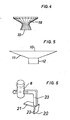
- FIG. 4 shows a further possible embodiment of the mounting roller 10, which is distinguished by a concave design and a profile 19 on the lateral surface.
- FIG. 5 shows an assembly roller 10 in which the first section 11 is conical and the second section 12 is cylindrical. It is important that the outer surfaces of the sections 11 and 12 again include an angle between 80 and 120 0th
- a mounting bracket 20, shown in perspective in FIG. 6, can be used as further mounting means, which has two legs 21, 22, which in turn enclose an angle between 80 and 120 °, preferably between 95 to 100 °.
- the legs 21, 22 can be provided with a friction-reducing covering, e.g. be made of PTFE.
- the mounting bracket 20 is attached to an angle bracket 23 with which it can be used in the device according to FIGS. 1 to 3 instead of the roller 10.
- Fig. 7 shows a particularly simple assembly device, which consists of the above-described mounting bracket and a mounting rod 24 which is rotatable about a guide rod 25.
- the guide rod 25 is arranged in the axis of the rim 13, a first peripheral section of the upper tire bead is again inserted into the interior of the rim 13 and fixed there.
- the mounting bracket 20 After the mounting bracket 20 has been positioned in the area of this section, it is guided along the circumference of the tire once using the rod 24.
- the second tire bead is assembled accordingly. It is advisable to fasten the rim 13 to the base 14 with the tire 14, e.g. with the help of a locking cone.
- the mounting rollers 10 described above can also be attached to the mounting rod 24.
Landscapes
- Engineering & Computer Science (AREA)
- Mechanical Engineering (AREA)
- Tires In General (AREA)
- Diaphragms For Electromechanical Transducers (AREA)
- Vehicle Body Suspensions (AREA)
Priority Applications (1)
| Application Number | Priority Date | Filing Date | Title |
|---|---|---|---|
| AT86101182T ATE42242T1 (de) | 1985-02-13 | 1986-01-30 | Verfahren und vorrichtung zur montage von fahrzeugluftreifen. |
Applications Claiming Priority (2)
| Application Number | Priority Date | Filing Date | Title |
|---|---|---|---|
| DE3504903 | 1985-02-13 | ||
| DE19853504903 DE3504903A1 (de) | 1985-02-13 | 1985-02-13 | Verfahren und vorrichtung zur montage von fahrzeugluftreifen |
Publications (3)
| Publication Number | Publication Date |
|---|---|
| EP0191367A2 true EP0191367A2 (fr) | 1986-08-20 |
| EP0191367A3 EP0191367A3 (en) | 1986-12-03 |
| EP0191367B1 EP0191367B1 (fr) | 1989-04-19 |
Family
ID=6262411
Family Applications (1)
| Application Number | Title | Priority Date | Filing Date |
|---|---|---|---|
| EP86101182A Expired EP0191367B1 (fr) | 1985-02-13 | 1986-01-30 | Méthode et dispositif pour le montage d'un pneumatique de roues de véhicule automobile |
Country Status (8)
| Country | Link |
|---|---|
| US (1) | US4702295A (fr) |
| EP (1) | EP0191367B1 (fr) |
| JP (1) | JPS61184104A (fr) |
| AT (1) | ATE42242T1 (fr) |
| CA (1) | CA1253784A (fr) |
| DE (2) | DE3504903A1 (fr) |
| ES (1) | ES296843Y (fr) |
| GR (1) | GR860411B (fr) |
Cited By (3)
| Publication number | Priority date | Publication date | Assignee | Title |
|---|---|---|---|---|
| EP0307650A1 (fr) * | 1987-08-20 | 1989-03-22 | WEILNHAMMER Maschinenbau GmbH | Appareil de montage pour pneumatiques |
| FR2635052A1 (fr) * | 1988-08-08 | 1990-02-09 | Vauthier Philippe | Dispositif d'aide au montage d'un bandage de pneumatique sur la jante d'une roue |
| EP0214323B1 (fr) * | 1985-09-04 | 1991-06-05 | Schenck Auto-Service-Geräte GmbH | Méthode pour monter ou démonter le bandage d'une roue de véhicule et dispositif pour sa mise en oeuvre |
Families Citing this family (8)
| Publication number | Priority date | Publication date | Assignee | Title |
|---|---|---|---|---|
| DE3733779A1 (de) * | 1987-10-06 | 1989-04-20 | Weilnhammer Maschb Gmbh | Montagevorrichtung fuer mindestens einen reifen |
| EP0338642A3 (fr) * | 1988-04-20 | 1990-05-30 | du Quesne, Francis | Appareil pour monter les pneus des roues de véhicules automobiles |
| US4969499A (en) * | 1989-08-30 | 1990-11-13 | Hennessey Industries, Inc. | Tire mounting apparatus |
| US6557610B2 (en) * | 1999-12-23 | 2003-05-06 | Fori Automation, Inc. | Tire bead seating station |
| FR2819218A1 (fr) * | 2001-01-11 | 2002-07-12 | Michelin Soc Tech | Procede de montage d'un pneumatique sur une jante, dispositif et outil pour la mise en oeuvre d'une etape de ce procede |
| JP5149189B2 (ja) * | 2005-10-06 | 2013-02-20 | アンドロイド インダストリーズ エルエルシー | タイヤ/ホイールビード混入物除去装置 |
| US7640963B2 (en) * | 2006-10-06 | 2010-01-05 | Android Industries Llc | Tire/wheel bead entrapment remover |
| US8191600B2 (en) * | 2008-12-31 | 2012-06-05 | Android Industries Llc | System and method for mounting a tire and a wheel |
Family Cites Families (7)
| Publication number | Priority date | Publication date | Assignee | Title |
|---|---|---|---|---|
| BE656570A (fr) * | 1964-12-03 | 1965-04-01 | ||
| US3826299A (en) * | 1972-09-08 | 1974-07-30 | D Curchod | Tyre changers |
| DE2648897C2 (de) * | 1976-10-28 | 1982-10-07 | Wilhelm 6349 Herbornseelbach Schäfer | Maschine zum Montieren und Demontieren von Fahrzeugreifen |
| DE3000428C2 (de) * | 1980-01-08 | 1988-04-14 | Continental Gummi-Werke Ag, 3000 Hannover | Fahrzeugrad |
| DE3233441A1 (de) * | 1982-09-09 | 1984-03-15 | Continental Gummi-Werke Ag, 3000 Hannover | Verfahren zur montage eines reifens |
| DE3334203A1 (de) * | 1983-09-22 | 1985-04-18 | Continental Gummi-Werke Ag, 3000 Hannover | Montagevorrichtung fuer fahrzeugluftreifen |
| DE3401476A1 (de) * | 1984-01-18 | 1985-07-25 | Gebr. Hofmann Gmbh & Co Kg Maschinenfabrik, 6100 Darmstadt | Montagevorrichtung fuer reifen |
-
1985
- 1985-02-13 DE DE19853504903 patent/DE3504903A1/de not_active Withdrawn
-
1986
- 1986-01-30 AT AT86101182T patent/ATE42242T1/de not_active IP Right Cessation
- 1986-01-30 EP EP86101182A patent/EP0191367B1/fr not_active Expired
- 1986-01-30 DE DE8686101182T patent/DE3662854D1/de not_active Expired
- 1986-02-06 CA CA000501213A patent/CA1253784A/fr not_active Expired
- 1986-02-11 ES ES1986296843U patent/ES296843Y/es not_active Expired
- 1986-02-12 GR GR860411A patent/GR860411B/el unknown
- 1986-02-12 JP JP61027013A patent/JPS61184104A/ja active Pending
- 1986-02-13 US US06/829,392 patent/US4702295A/en not_active Expired - Fee Related
Cited By (3)
| Publication number | Priority date | Publication date | Assignee | Title |
|---|---|---|---|---|
| EP0214323B1 (fr) * | 1985-09-04 | 1991-06-05 | Schenck Auto-Service-Geräte GmbH | Méthode pour monter ou démonter le bandage d'une roue de véhicule et dispositif pour sa mise en oeuvre |
| EP0307650A1 (fr) * | 1987-08-20 | 1989-03-22 | WEILNHAMMER Maschinenbau GmbH | Appareil de montage pour pneumatiques |
| FR2635052A1 (fr) * | 1988-08-08 | 1990-02-09 | Vauthier Philippe | Dispositif d'aide au montage d'un bandage de pneumatique sur la jante d'une roue |
Also Published As
| Publication number | Publication date |
|---|---|
| ES296843U (es) | 1988-01-16 |
| US4702295A (en) | 1987-10-27 |
| DE3504903A1 (de) | 1986-08-14 |
| EP0191367B1 (fr) | 1989-04-19 |
| JPS61184104A (ja) | 1986-08-16 |
| DE3662854D1 (en) | 1989-05-24 |
| ATE42242T1 (de) | 1989-05-15 |
| CA1253784A (fr) | 1989-05-09 |
| GR860411B (en) | 1986-06-03 |
| ES296843Y (es) | 1988-09-16 |
| EP0191367A3 (en) | 1986-12-03 |
Similar Documents
| Publication | Publication Date | Title |
|---|---|---|
| DE602005005103T2 (de) | Automatische Radmontier- und Demontiervorrichtung | |
| DE69815497T2 (de) | Reifendemontiervorrichtung und Zubehör | |
| EP0141164B1 (fr) | Dispositif de montage de pneumatiques pour véhicules automobiles | |
| DE19704163A1 (de) | Achsmeßhalter zur Befestigung eines Meßkopfes an einer Felge eines Fahrzeugrades | |
| EP0154715B1 (fr) | Dispositif de montage pour pneumatiques | |
| EP0191367B1 (fr) | Méthode et dispositif pour le montage d'un pneumatique de roues de véhicule automobile | |
| DE2213779C3 (de) | Vorrichtung für die Demontage und Montage von Reifen auf Felgen | |
| EP1630010B1 (fr) | Dispositif et procédé pour le montage d'un pneumatique | |
| DE60002779T2 (de) | Reifendemontiervorrichtung für "system pax"- Reifen oder ähnlichem | |
| EP0792761B1 (fr) | Dispositif d'amélioration du comportement des pneumatiques automobiles par un meilleur positionnement des talons des pneus sur la jante | |
| DE69300839T2 (de) | Apparat zum Montieren von Speichen eines Speichenrades zwischen die Nabe und Felge. | |
| DE10149086C1 (de) | Verfahren zum Herstellen eines Notlauf-Stützkörpers für Notlauf-Fahrzeugräder | |
| DE1605696C3 (de) | Vorrichtung zur Montage eines Fahrzeugreifens auf eine Felge | |
| EP0170124A2 (fr) | Méthode et dispositif pour le démontage d'un pneumatique | |
| DE10222164C1 (de) | Vorrichtung zum Montieren eines Luftreifens auf eine Felge eines Kraftfahrzeugrades | |
| DE2330528A1 (de) | Vorrichtung zum reifenwechsel an fahrzeugraedern | |
| DE4006037A1 (de) | Verfahren und vorrichtung zum montieren eines kraftfahrzeugreifens auf eine radfelge | |
| DE3331596C2 (de) | Verfahren zum Aufbringen eines Überzugs auf eine zylindrische Platte und Vorrichtung zur Durchführung des Verfahrens | |
| DE3438615A1 (de) | Montagevorrichtung fuer fahrzeugluftreifen | |
| EP0307650A1 (fr) | Appareil de montage pour pneumatiques | |
| DE3344737C2 (fr) | ||
| DE3733779C2 (fr) | ||
| DE7525170U (de) | Hilfswerkzeug für die Montage von Kraftfahrzeugreifen | |
| DE3520801A1 (de) | Verfahren und vorrichtung zur demontage von fahrzeugluftreifen | |
| DE2621236C3 (de) | Montage- und Demontagevorrichtung für Reifen |
Legal Events
| Date | Code | Title | Description |
|---|---|---|---|
| PUAI | Public reference made under article 153(3) epc to a published international application that has entered the european phase |
Free format text: ORIGINAL CODE: 0009012 |
|
| AK | Designated contracting states |
Kind code of ref document: A2 Designated state(s): AT BE CH DE FR GB IT LI LU NL SE |
|
| PUAL | Search report despatched |
Free format text: ORIGINAL CODE: 0009013 |
|
| AK | Designated contracting states |
Kind code of ref document: A3 Designated state(s): AT BE CH DE FR GB IT LI LU NL SE |
|
| 17P | Request for examination filed |
Effective date: 19861213 |
|
| 17Q | First examination report despatched |
Effective date: 19880219 |
|
| RAP1 | Party data changed (applicant data changed or rights of an application transferred) |
Owner name: CONTINENTAL AKTIENGESELLSCHAFT |
|
| GRAA | (expected) grant |
Free format text: ORIGINAL CODE: 0009210 |
|
| AK | Designated contracting states |
Kind code of ref document: B1 Designated state(s): AT BE CH DE FR GB IT LI LU NL SE |
|
| REF | Corresponds to: |
Ref document number: 42242 Country of ref document: AT Date of ref document: 19890515 Kind code of ref document: T |
|
| REF | Corresponds to: |
Ref document number: 3662854 Country of ref document: DE Date of ref document: 19890524 |
|
| ITF | It: translation for a ep patent filed | ||
| ET | Fr: translation filed | ||
| GBT | Gb: translation of ep patent filed (gb section 77(6)(a)/1977) | ||
| PGFP | Annual fee paid to national office [announced via postgrant information from national office to epo] |
Ref country code: LU Payment date: 19891229 Year of fee payment: 5 |
|
| PG25 | Lapsed in a contracting state [announced via postgrant information from national office to epo] |
Ref country code: LU Free format text: LAPSE BECAUSE OF NON-PAYMENT OF DUE FEES Effective date: 19900131 |
|
| PGFP | Annual fee paid to national office [announced via postgrant information from national office to epo] |
Ref country code: NL Payment date: 19900131 Year of fee payment: 5 |
|
| PLBE | No opposition filed within time limit |
Free format text: ORIGINAL CODE: 0009261 |
|
| STAA | Information on the status of an ep patent application or granted ep patent |
Free format text: STATUS: NO OPPOSITION FILED WITHIN TIME LIMIT |
|
| 26N | No opposition filed | ||
| ITTA | It: last paid annual fee | ||
| PG25 | Lapsed in a contracting state [announced via postgrant information from national office to epo] |
Ref country code: NL Effective date: 19910801 |
|
| NLV4 | Nl: lapsed or anulled due to non-payment of the annual fee | ||
| PGFP | Annual fee paid to national office [announced via postgrant information from national office to epo] |
Ref country code: CH Payment date: 19920115 Year of fee payment: 7 |
|
| PGFP | Annual fee paid to national office [announced via postgrant information from national office to epo] |
Ref country code: SE Payment date: 19920121 Year of fee payment: 7 |
|
| PGFP | Annual fee paid to national office [announced via postgrant information from national office to epo] |
Ref country code: BE Payment date: 19920127 Year of fee payment: 7 |
|
| PGFP | Annual fee paid to national office [announced via postgrant information from national office to epo] |
Ref country code: AT Payment date: 19920130 Year of fee payment: 7 |
|
| PGFP | Annual fee paid to national office [announced via postgrant information from national office to epo] |
Ref country code: DE Payment date: 19920317 Year of fee payment: 7 |
|
| PGFP | Annual fee paid to national office [announced via postgrant information from national office to epo] |
Ref country code: GB Payment date: 19921209 Year of fee payment: 8 |
|
| PGFP | Annual fee paid to national office [announced via postgrant information from national office to epo] |
Ref country code: FR Payment date: 19930127 Year of fee payment: 8 |
|
| PG25 | Lapsed in a contracting state [announced via postgrant information from national office to epo] |
Ref country code: AT Effective date: 19930130 |
|
| PG25 | Lapsed in a contracting state [announced via postgrant information from national office to epo] |
Ref country code: SE Effective date: 19930131 Ref country code: LI Effective date: 19930131 Ref country code: CH Effective date: 19930131 Ref country code: BE Effective date: 19930131 |
|
| BERE | Be: lapsed |
Owner name: CONTINENTAL A.G. Effective date: 19930131 |
|
| REG | Reference to a national code |
Ref country code: CH Ref legal event code: PL |
|
| PG25 | Lapsed in a contracting state [announced via postgrant information from national office to epo] |
Ref country code: DE Effective date: 19931001 |
|
| PG25 | Lapsed in a contracting state [announced via postgrant information from national office to epo] |
Ref country code: GB Effective date: 19940130 |
|
| GBPC | Gb: european patent ceased through non-payment of renewal fee |
Effective date: 19940130 |
|
| PG25 | Lapsed in a contracting state [announced via postgrant information from national office to epo] |
Ref country code: FR Effective date: 19940930 |
|
| REG | Reference to a national code |
Ref country code: FR Ref legal event code: ST |
|
| EUG | Se: european patent has lapsed |
Ref document number: 86101182.3 Effective date: 19930810 |
|
| PG25 | Lapsed in a contracting state [announced via postgrant information from national office to epo] |
Ref country code: IT Free format text: LAPSE BECAUSE OF NON-PAYMENT OF DUE FEES Effective date: 20050130 |