EP0191482A2 - Gleichstromwandler - Google Patents
Gleichstromwandler Download PDFInfo
- Publication number
- EP0191482A2 EP0191482A2 EP86101793A EP86101793A EP0191482A2 EP 0191482 A2 EP0191482 A2 EP 0191482A2 EP 86101793 A EP86101793 A EP 86101793A EP 86101793 A EP86101793 A EP 86101793A EP 0191482 A2 EP0191482 A2 EP 0191482A2
- Authority
- EP
- European Patent Office
- Prior art keywords
- winding
- voltage
- converter
- reset
- saturable reactor
- Prior art date
- Legal status (The legal status is an assumption and is not a legal conclusion. Google has not performed a legal analysis and makes no representation as to the accuracy of the status listed.)
- Granted
Links
Images


Classifications
-
- G—PHYSICS
- G05—CONTROLLING; REGULATING
- G05F—SYSTEMS FOR REGULATING ELECTRIC OR MAGNETIC VARIABLES
- G05F1/00—Automatic systems in which deviations of an electric quantity from one or more predetermined values are detected at the output of the system and fed back to a device within the system to restore the detected quantity to its predetermined value or values, i.e. retroactive systems
- G05F1/10—Regulating voltage or current
- G05F1/12—Regulating voltage or current wherein the variable actually regulated by the final control device is AC
- G05F1/32—Regulating voltage or current wherein the variable actually regulated by the final control device is AC using magnetic devices having a controllable degree of saturation as final control devices
- G05F1/34—Regulating voltage or current wherein the variable actually regulated by the final control device is AC using magnetic devices having a controllable degree of saturation as final control devices combined with discharge tubes or semiconductor devices
- G05F1/38—Regulating voltage or current wherein the variable actually regulated by the final control device is AC using magnetic devices having a controllable degree of saturation as final control devices combined with discharge tubes or semiconductor devices semiconductor devices only
-
- H—ELECTRICITY
- H02—GENERATION; CONVERSION OR DISTRIBUTION OF ELECTRIC POWER
- H02M—APPARATUS FOR CONVERSION BETWEEN AC AND AC, BETWEEN AC AND DC, OR BETWEEN DC AND DC, AND FOR USE WITH MAINS OR SIMILAR POWER SUPPLY SYSTEMS; CONVERSION OF DC OR AC INPUT POWER INTO SURGE OUTPUT POWER; CONTROL OR REGULATION THEREOF
- H02M3/00—Conversion of DC power input into DC power output
- H02M3/22—Conversion of DC power input into DC power output with intermediate conversion into AC
- H02M3/24—Conversion of DC power input into DC power output with intermediate conversion into AC by static converters
- H02M3/28—Conversion of DC power input into DC power output with intermediate conversion into AC by static converters using discharge tubes with control electrode or semiconductor devices with control electrode to produce the intermediate AC
- H02M3/325—Conversion of DC power input into DC power output with intermediate conversion into AC by static converters using discharge tubes with control electrode or semiconductor devices with control electrode to produce the intermediate AC using devices of a triode or a transistor type requiring continuous application of a control signal
- H02M3/335—Conversion of DC power input into DC power output with intermediate conversion into AC by static converters using discharge tubes with control electrode or semiconductor devices with control electrode to produce the intermediate AC using devices of a triode or a transistor type requiring continuous application of a control signal using semiconductor devices only
- H02M3/33538—Conversion of DC power input into DC power output with intermediate conversion into AC by static converters using discharge tubes with control electrode or semiconductor devices with control electrode to produce the intermediate AC using devices of a triode or a transistor type requiring continuous application of a control signal using semiconductor devices only of the forward type
Definitions
- the present invention relates to a DC-DC converter and more particularly, to a DC-DC converter controlled by a magnetic amplifier consisting essencially of a saturable reactor.
- a magnetic amplifier-controlled, stabilized power supply comprising a saturable reactor has already been known. Since this type of power supply converts DC input voltage to stabilized DC output voltage, it is called a DC-DC converter.
- This type of power supply converts DC input voltage to stabilized DC output voltage, it is called a DC-DC converter.
- This switching regulator (DC-DC converter) comprises a DC power supply 1 for supplying DC voltage to be stabilized, a transformer 2 having a primary winding 21 connected to the DC power supply 1 and a secondary winding 22, a transistor 3 whose collector is connected to the primary winding 21 and whose emitter is to the DC power supply 1.
- a self-oscillating circuit 4 in parallel with the DC power supply is connected to the base of the transistor 3 to turn on the transistor 3 on a periodical basis.
- a saturable reactor 5 Connected to the secondary winding 22 is a saturable reactor 5 to which an anode of a rectifying diode 6 is in turn connected.
- a cathode of the diode 6 is then connected to a choke coil 8 which leads to one output terminal 12.
- Another rectifying diode 7 is connected between the other end of the secondary winding 22 and the choke coil 8.
- a capacitor 9 is provided between output terminals 12, 13.
- the capacitor 9 and the choke coil 8 form a smoothing circuit, namely, an L-C filter.
- Terminals 12 and 13 are a positive output terminal and a negative output terminal, respectively.
- the other end of the secondary winding 22 of the transformer 2 is connected to the negative output terminal 13.
- An emitter of a transistor 10 for controlling the resetting of the saturable reactor 5 is connected to the positive output terminal 12, and a collector thereof is connected to a point between the saturable reactor 5 and the anode of the diode 6.
- a base of the transistor 10 is connected to a reset control circuit 11.
- the reset control circuit 11 receives output voltage which is compared with referance voltage to produce an error signal.
- the error signal is applied to the base of the transistor 10 to turn on and off the transistor 10 so that proper reset current ir is supplied to the saturable reactor 5 for purpose of controlling the output voltage Vo.
- the output voltage Vo is used as a power source for reset current ir.
- this switching regulator has a problem that the saturable reactor 5 undergoes extraordinary temperature rise during the operation.
- the cause of such extraordinary temperature rise is that resonance current is generated during the turn-off period of the transistor 3 by junction capacitance of the switching transistor 3, capacitance in a snubber circuit connected in parallel to the transistor 3 for absorbing surge voltage which appears at the time of turning off the transistor 3, and inductance of the primary winding 21 of the transformer 2, and that it is applied to the saturable reactor 5 through magnetic coupling of the primary and secondary windings 21 and 22.
- Fig. 4 is an equivalent circuit to Fig. 3.
- the transformer 2 is expressed by an exciting inductance Lex and two leakage inductances Ln 1 and Ln 2 , and that a capacitor 50 is inserted in parallel with the switching transistor 3.
- the capacitor 50 represents part of a snubber circuit.
- discharge current id which may be called “resonance current” flows from the capacitor 50, inducing voltage V L in the exciting inductance Lex.
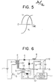
- the relation between the discharge current id and the induced voltage V L is schematically shown in Fig. 5.
- the discharge current id begins flowing when the transformer 2 has been reset, namely when the transformer's core has returned to an original state in which it has a residual magnetic flux density Br.
- the discharge current id is decreasing, the induced voltage V L is positive and increasing.
- This voltage V L is applied to the saturable reactor 5.
- a positive part of the voltage V L is shown by a hatched portion in Fig. 2. Since this resonance current causes the magnetization of the saturable reactor 5, it contributes to the temperature rise of the saturable reactor 5.
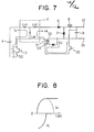
- a magnetic control-type switching regulator equipped with a saturable reactor 5 having first and second windings, which is shown in Fig. 6.
- An essential feature of this switching regulator is that a saturable reactor 5 has two windings; a first winding 52 connected to an end of a secondary winding 22 which is negative while a switching transistor 3 is in a turn-on state, and a second winding 53 connected between a transistor 10 connected to a positive side of a capacitor 9 and a diode 15 which is in turn connected to a negative output terminal 13.
- 51 denotes a magnetic core of the saturable reactor.
- reset current ir flows along the broken line shown in Fig. 6, without passing through the secondary winding 22 of the transformer 2.
- Fig. 7 shows an equivalent circuit to Fig. 6. It is to be noted that since the first and second windings 52 and 53 of the saturable reactor 5 are magnetically coupled with each other, the reset current ir flowing through the second winding 53 induces current iM in the first winding 52. Since these two windings 52 and 53 have the same polarity, namely their positive polarity ends are on the same side, the current iM flows through Lex in the same direction as the discharge current id. Therefore, while the discharge current id is decreasing, the current iM substantially offsets the decrease in the discharge curret id, leading to minimal voltage V L .
- the transformer 2 would generate substantially no voltage despite the discharge current. This is schematically shown in Fig. 8. Because of this feature, the saturable reactor 5 is free from extraordinary heating.
- the switching regulator of Fig. 6 still has a problem, which is detrimental to switching regulators as means for supplying stabilized DC voltage.
- the problem is that it generates noises which are not always sufficiently low.
- regulations such as those of U.S. Federal Communication Committee (FCC) and Verband Deutscher Elektrotechniker (VDE) are becoming stricter on switching regulation's noises, reducing a noise level as low as possible is extremely desired.
- An object of the present invention is, therefore, to provide a DC-DC converter for providing DC output voltage stabilized by magnetic control using a saturable reactor, which suffers only from a greatly'reduced level of noises.
- the inventors have found, through extensive research, that noises can be greatly reduced by connecting a saturable reactor having two windings to an end of a secondary winding of a transformer which is positive while a switching transistor for a primary winding of the transformer is in a turn-on state.
- the present invention is based on this finding.
- the DC-DC converter comprises a transformer comprising a primary winding and at least one secondary winding; means for supplying DC voltage to the primary winding; at least one switching element connected in series between the DC voltage supplying means and the primary winding; rectifying means; at least one saturable reactor comprising a first winding and a second winding, the first winding being connected between one end of the secondary winding which is positive while the switching element is in a turn-on state and the rectifying means; and reset control circuit means connected to the second winding of the saturable reactor for supplying reset current thereto in response to output voltage of the rectifying means.
- the first and second windings have such polarities that the reset current can reset the saturable reactor.
- Fig. 9 shows a DC-DC converter according to one embodiment of the present invention.
- the DC-DC converter has a DC power supply 101 and a transformer 102 which has a primary winding 121 and a secondary winding 122.
- the DC power supply 101 is connected to the primary winding 121.
- a switching transistor 103 is interposed between the DC power supply 101 and the primary winding 121 in such a manner that its collector is connected to the primary winding 121 and its emitter is to the DC power supply.
- the base of the transistor 103 is connected to an oscillator 104.
- a saturable reactor 105 Connected to the secondary winding 122 is a saturable reactor 105 having a magnetic core 151, a first winding 152 and a second winding 153.
- the first winding 152 which may be called “gate winding”
- the second winding 153 which may be called “control winding”
- the other end of the secondary winding 122 which is negative while the switching transistor 103 is in a turn-on state.
- the other end of the first winding 152 is connected to an anode of a diode 106, and a cathod of the diode 106 is in turn connected to a choke coil 108.
- a diode 107 is interposed between a point 109 between the diode 106 and the choke coil 108 and a line 110 connecting the secondary winding 122 and one output terminal 113.
- the other output terminal 112 is connected to the choke coil 108.
- a capacitor 114 Connected between the output terminals 112 and 113 is a capacitor 114 which forms, together with the choke coil 108, an L-C filter for smoothing output voltage.
- a reset control circuit,115 is connected to the second winding 153 via a diode 116.
- the diode 116 is directed so as to cause reset current ir to flow along the broken line as shown in Fig. 9.
- a load 117 may be connected between the output terminals 112 and 113.
- the reset current does not have enough voltage.
- This problem can be easily solved by choosing an appropriate turn ratio of the two windings 152, 153 of the saturable reactor 105. That is, voltage applied to the saturable reactor 105 by the controlling winding 153 is Vo x n M1 /n M2 , wherein Vo is output voltage, and n M1 and nM 2 are the numbers of turns of the first and second windings 152, 153, respectively.
- Vo output voltage
- n M1 and nM 2 are the numbers of turns of the first and second windings 152, 153, respectively.
- the reset current ir can be taken from any other source, and that if such source has high voltage enough to completely reset the saturable reactor 105, the first and second windings 152, 153 may have an equal number of turns.
- the DC-DC converter according to the present invention is very advantageous in that it suffers only from a greatly reduced level of noise generation.
- a low level of noises is highly desired.
- noises which may be generated by DC-DC converters or switching regulators, a low-frequency radiation noise, a high-frequency radiation noise and a noise expressed by "noise terminal voltage" are important.
- the low-frequency radiation noises affect radio sets, etc.
- the high-frequency radiation noises affect computers, TV sets, etc.
- the noise terminal voltage is a measure of how large noises are returned from the switching regulator to an input line through input terminals. Noises returned to an input line may go into another equipment through other outlets, causing operational errors in another equipment.
- Fig. 11 shows another embodiment of the present invention directed to a multiple-output DC-DC converter.
- this DC-DC converter contains a first circuit for providing a first output V 01 and a second circuit for providing a second output V 02 , and that the second circuit is essentially the same as that of Fig. 9.
- a reset control circuit 215 contains resistors 271, 273, 274, 275, 277 and 278, a transistor 272 and a shunt regulator 276 which is composed of a variable Zener diode, cathod-anode voltage of which is variable depending on a reference voltage level. Voltage devided by the resistors 277 and 278 is applied to a reference terminal of the shunt regulator 276.
- Reference terminal voltage varies depending on the output voltage V 02' leading to the variation of the cathod-anode voltage, which in turn changes bias voltage applied to a base of the transistor 272.
- the reset current ir can be controlled to stabilize the output voltage.
- output voltage V 01 is sent to a control circuit 260 which controls a switching transistor 204 connected to a primary winding 221 of a transformer 202.
- Fig. 12 shows a still other embodiment of the present invention in which a DC-DC converter contains a pair of switching transistors and a pair of saturable reactors.
- This half bridge-type DC-DC converter has a DC power supply 301 whose voltage is equally devided by capacitors 330 and 331.
- a pair of switching transistors 303a, 303b each connected to oscillators 304a, 304b are connected in series between positive and negative ends of a DC power source 301.
- a primary winding 321 of a transformer 302 is connected between a point between the two switching transistors and a point between the two capacitors 330, 331.
- a secondary winding has a center tap which is connected to a negative output terminal 313.
- An upper half of the secondary winding 332a is connected at its positive end to a first winding 352a of a first saturable reactor 305a.
- a lower half of the secondary winding 332b is also connected at its positive end to a first winding 352b of a second saturable reactor 305b.
- the first windings 352a, 352b are connected to a choke coil 308 via diodes 306a, 306b, respectively.
- a capacitor 314 is connected between positive and negative output terminals 312, 313.
- Second windings 353a, 353b and a diode 316 are connected in series to a reset control circuit 315 which provides reset current ir in response to output voltage V 0 .
- the oscillators 304a, 304b supply current for turning on the transistors 303a, 303b alternatingly with some intervals.
- voltage flows through a primary winding 321 with its positive polarity on the dotted side, inducing in a secondary winding 322 voltage whose positive polarity is on the dotted side.
- the induced current flows through the saturable reactor 305a, the diode 306a and the choke coil 308.
- voltage v 0 appears at the capacitor 314 with its positive polarity on the side of the positive output terminal 312.
- Second windings 353a, 353b are connected in series in such a manner that the second winding 353a and the first winding 352a have the same polarity, while the second winding 353b and the first winding 352b have a different polarity.
- the two saturable reactors 305a, 305b work in the same manner.
- the first and second windings 352a-353a, 352b-353b are magnetically coupled so that unnecessary voltage due to the resonance current is not substantially applied to it.
- a time chart of voltages V 2 , V SR and V 2 ' is shown in Fig. 13.
- Fig. 14 shows a still further embodiment of the present invention which is a push-pull DC-DC converter.
- a circuit on the secondary winding side is completely the same as that of Fig. 12.
- a primary winding has a positive end connected to a collector of a switching transistor 303a and a negative end connected to a collector of a switching transistor 303b. Both emitters of the transistors 303a, 303b are connected to each other, and a DC power source 301 is connected between a center tap of the primary winding and a point between the transistors 303a, 303b.
- This push-pull DC-DC converter works essentially in the same manner without causing any extraordinary temperature rise of the saturable reactors.
- Fig. 15 shows a still further embodiment of the present invention which is a full-bridge DC-DC converter. Again, a portion of the circuit on the side of a secondary winding is completely the same as that of Fig. 12. Therefore, reference numerals are omitted.
- transistors 403a, 404b are turned on by an oscillator 405
- transistors 404a, 403b are turned on by an oscillator 406
- current flows back and forth through the primary winding 421, enabling this full-bridge DC-DC converter to work in the same manner as the half-bridge DC-DC converter.
- Fig. 16 shows a sill further embodiment of the present invention which is a multiple-output DC-DC converter.
- Two output circuits are the same as that of Fig. 12, except that an upper part of the output circuit does not contain saturable reactors. Thus, no reference numerals are assigned thereto.
- Output voltage V Ol of the upper part of the circuit is sent to a control circuit 560 which controls the widths of pulses supplied to bases of switching transistors 503a, 503b, so that stable output may be provided.
- the extraordinary temperature rise of two saturable reactors can be avoided as in Fig. 12.
- Fig. 17 shows a specific circuit of the reset control circuit 115 suitable for the present invention. Terminals 1, 2 and 3 are connected to the positive terminal 112, a terminal 4 is to the diode 116, and a terminal 5 is to the negative terminal 113.
- V cc of a linear amplifier 31 is connected to a terminal 2 and -V cc is connected to a terminal 3.
- a terminal 1 is connected to an inverting input of the linear amplifier 31 through a resistor 32.
- One end of a resistor 33 is connected to V cc and the other end thereof is connected to a non-inverting input of the linear amplifier 31 through a resistor 34.
- a resistor 35, a capacitor 39 and a cathode of a Zener diode 43 are connected to the resistors 33 and 34.
- the other ends of the resistor 35 and capacitor 39 and an anode of the Zener diode 43 are connected to -V .
- a resistor 36 is connected between the inverting input of the linear amplifier 31 and an output thereof.
- the output of the linear amplifier is further connected to a base of a transistor 42 through a resistor 37.
- An emitter of the transistor 42 is connected to a terminal 3 and a collector thereof is connected to a base of a transistor 41 through a resistor 38.
- a collector of the transistor 41 is connected to the terminal 0 and an emitter thereof is connected to a terminal 4 through a diode 40.
- a reference voltage which is generated by a reference voltage generator constituted by the resistors 33 and 35, capacitor 39 and Zener diode 43 is compared with a detection signal v indicative of the output voltage V 0 , so that output determined by their difference is generated from the linear amplifier 31.
- the transistors 41 and 42 control the current flowing from the terminal 3 to the terminal 4 on the basis of the output of the linear amplifier 31.
- the terminals 2 and 3 are connected to a power source necessary for operating the reset control circuit 115.
- the reset current i flowing through the second winding 153 of the saturable reactor 16 is controlled in accordance with the difference between the reference voltage and the detection voltage v s , thereby regulating the output voltage V 0 .
- the reset current i r flows along the path indicated by the broken line in Fig. 9.
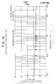
- Figs. 18-20 clearly show that the DC-DC converter of the present invention is much superior to the prior art DC-DC converter of Fig. 6 in respect of low noise generation. Since the DC-DC converter of the present invention does not substantially suffer from the racheting of a transformer and extraordinary temperature rise of a saturable reactor, it is highly suitable for any applications requiring stable DC voltage.
Landscapes
- Engineering & Computer Science (AREA)
- Power Engineering (AREA)
- Physics & Mathematics (AREA)
- Electromagnetism (AREA)
- General Physics & Mathematics (AREA)
- Radar, Positioning & Navigation (AREA)
- Automation & Control Theory (AREA)
- Dc-Dc Converters (AREA)
Applications Claiming Priority (4)
| Application Number | Priority Date | Filing Date | Title |
|---|---|---|---|
| JP2489885 | 1985-02-12 | ||
| JP24898/85 | 1985-02-12 | ||
| JP13520385 | 1985-06-20 | ||
| JP135203/85 | 1985-06-20 |
Publications (3)
| Publication Number | Publication Date |
|---|---|
| EP0191482A2 true EP0191482A2 (de) | 1986-08-20 |
| EP0191482A3 EP0191482A3 (en) | 1987-10-21 |
| EP0191482B1 EP0191482B1 (de) | 1990-07-25 |
Family
ID=26362477
Family Applications (1)
| Application Number | Title | Priority Date | Filing Date |
|---|---|---|---|
| EP86101793A Expired EP0191482B1 (de) | 1985-02-12 | 1986-02-12 | Gleichstromwandler |
Country Status (3)
| Country | Link |
|---|---|
| US (1) | US4811187A (de) |
| EP (1) | EP0191482B1 (de) |
| DE (1) | DE3672847D1 (de) |
Cited By (6)
| Publication number | Priority date | Publication date | Assignee | Title |
|---|---|---|---|---|
| EP0183504A3 (en) * | 1984-11-26 | 1987-11-04 | Tektronix, Inc. | A regulated high voltage supply |
| EP0366314A1 (de) * | 1988-10-24 | 1990-05-02 | AT&T Corp. | Steuergerät mit einem einzigen magnetischen Verstärker zum Regulieren von zwei Spannungsausgängen eines Umformers |
| DE4112676A1 (de) * | 1990-06-06 | 1991-12-19 | Asea Brown Boveri | Ac/dc konverter |
| EP0465903A1 (de) * | 1990-07-13 | 1992-01-15 | André Bonnet | Magnetisches Steuerverfahren von Energieübertragung in einem statischen Konverter |
| FR2829314A1 (fr) * | 2001-09-04 | 2003-03-07 | Renault | Dispositif de commande d'un actuateur piezo-electrique et son procede de mise en oeuvre |
| CN104052256A (zh) * | 2013-03-12 | 2014-09-17 | 浙江海洋学院 | 单极性开关电源续流降噪及其参数计算方法 |
Families Citing this family (61)
| Publication number | Priority date | Publication date | Assignee | Title |
|---|---|---|---|---|
| US4916590A (en) * | 1989-07-06 | 1990-04-10 | Spectra-Physics | Series resonant magnetic amplifier power supply |
| US5256889A (en) * | 1989-09-20 | 1993-10-26 | Hitachi, Ltd. | Semiconductor rectifying diode with PN geometry |
| US4967335A (en) * | 1989-09-21 | 1990-10-30 | Zenith Electronics Corp. | Saturable transformer regulator for flyback power supply |
| US5231563A (en) * | 1990-09-07 | 1993-07-27 | Itt Corporation | Square wave converter having an improved zero voltage switching operation |
| US5126931A (en) * | 1990-09-07 | 1992-06-30 | Itt Corporation | Fixed frequency single ended forward converter switching at zero voltage |
| US5132889A (en) * | 1991-05-15 | 1992-07-21 | Ibm Corporation | Resonant-transition DC-to-DC converter |
| US5157592A (en) * | 1991-10-15 | 1992-10-20 | International Business Machines Corporation | DC-DC converter with adaptive zero-voltage switching |
| JPH05336752A (ja) * | 1992-05-27 | 1993-12-17 | Hitachi Ltd | スイッチングレギュレータ |
| JP2803943B2 (ja) * | 1992-10-21 | 1998-09-24 | アルプス電気株式会社 | 非接触電力供給装置 |
| JPH06351239A (ja) * | 1993-06-01 | 1994-12-22 | Masashi Mukogawa | 電圧変換装置 |
| JP2758552B2 (ja) * | 1993-08-27 | 1998-05-28 | 浜松ホトニクス株式会社 | プッシュプル共振型スイッチング電源回路 |
| US5418703A (en) * | 1993-08-31 | 1995-05-23 | International Business Machines Corp. | DC-DC converter with reset control for enhanced zero-volt switching |
| US5539630A (en) * | 1993-11-15 | 1996-07-23 | California Institute Of Technology | Soft-switching converter DC-to-DC isolated with voltage bidirectional switches on the secondary side of an isolation transformer |
| US5612862A (en) * | 1994-05-06 | 1997-03-18 | Alcatel Network Systems, Inc. | Method and circuitry for controlling current reset characteristics of a magnetic amplifier control circuit |
| US5521808A (en) * | 1994-05-06 | 1996-05-28 | Alcatel Network Systems, Inc. | Method and circuitry for controlling start-up characteristics of a magnetic amplifier control circuit |
| US5731966A (en) * | 1996-06-17 | 1998-03-24 | Lucent Technologies Inc. | Snubber circuit for rectifying diodes and method of operation thereof |
| US5930123A (en) * | 1996-08-14 | 1999-07-27 | Reltec Corporation | Reset circuit for current transformer having a short reset interval |
| JPH1141927A (ja) * | 1997-07-16 | 1999-02-12 | Fujitsu Ltd | Dc/dcコンバータ |
| US5956238A (en) * | 1998-06-24 | 1999-09-21 | Celestica North America Inc. | Blocking time maintenance circuit for ZVS converters |
| US6014326A (en) * | 1998-10-27 | 2000-01-11 | Hewlett-Packard Company | Half-bridge balancing circuit |
| US6147476A (en) * | 1999-02-23 | 2000-11-14 | Deltron, Inc. | Two quadrant magamp regulator control circuit with fast dynamic response and full holdoff capability |
| US6191960B1 (en) * | 2000-05-09 | 2001-02-20 | Lucent Technologies Inc. | Active clamp for isolated power converter and method of operating thereof |
| WO2002039567A2 (en) * | 2000-11-08 | 2002-05-16 | Munetix, Inc. | Magnetic amplifier ac/dc converter with primary side regulation |
| US6490184B2 (en) * | 2001-03-16 | 2002-12-03 | Delta Electronics, Inc. | Auxiliary output voltage control implemented with a bi-directionally magnetizing magnetic amplifier |
| US6385058B1 (en) * | 2001-05-17 | 2002-05-07 | Northrop Grumman | Active bleed voltage balancing circuit |
| US6501666B1 (en) * | 2001-08-15 | 2002-12-31 | System General Corp. | Method and apparatus for magnetic amplifier to reduce minimum load requirement |
| US6785151B2 (en) * | 2002-03-16 | 2004-08-31 | Condor D.C. Power Supplies, Inc. | Quasi-synchronous, magnetic amplifier regulated dc-dc converter |
| JP4671020B2 (ja) * | 2005-01-28 | 2011-04-13 | サンケン電気株式会社 | 多出力共振型dc−dcコンバータ |
| JP2008048513A (ja) * | 2006-08-11 | 2008-02-28 | Toshiba Corp | 半導体電力変換制御装置 |
| US8000118B1 (en) | 2010-03-15 | 2011-08-16 | Varentec Llc | Method and system for delivering a controlled voltage |
| JP2018025190A (ja) * | 2016-08-09 | 2018-02-15 | サンケン電気株式会社 | 点火装置 |
| US10809134B2 (en) | 2017-05-24 | 2020-10-20 | Cisco Technology, Inc. | Thermal modeling for cables transmitting data and power |
| US11054457B2 (en) | 2017-05-24 | 2021-07-06 | Cisco Technology, Inc. | Safety monitoring for cables transmitting data and power |
| US10541758B2 (en) | 2017-09-18 | 2020-01-21 | Cisco Technology, Inc. | Power delivery through an optical system |
| US11431420B2 (en) | 2017-09-18 | 2022-08-30 | Cisco Technology, Inc. | Power delivery through an optical system |
| US11093012B2 (en) | 2018-03-02 | 2021-08-17 | Cisco Technology, Inc. | Combined power, data, and cooling delivery in a communications network |
| US10281513B1 (en) | 2018-03-09 | 2019-05-07 | Cisco Technology, Inc. | Verification of cable application and reduced load cable removal in power over communications systems |
| US10732688B2 (en) | 2018-03-09 | 2020-08-04 | Cisco Technology, Inc. | Delivery of AC power with higher power PoE (power over ethernet) systems |
| US10631443B2 (en) | 2018-03-12 | 2020-04-21 | Cisco Technology, Inc. | Splitting of combined delivery power, data, and cooling in a communications network |
| US10672537B2 (en) | 2018-03-30 | 2020-06-02 | Cisco Technology, Inc. | Interface module for combined delivery power, data, and cooling at a network device |
| US10958471B2 (en) | 2018-04-05 | 2021-03-23 | Cisco Technology, Inc. | Method and apparatus for detecting wire fault and electrical imbalance for power over communications cabling |
| US10735105B2 (en) | 2018-05-04 | 2020-08-04 | Cisco Technology, Inc. | High power and data delivery in a communications network with safety and fault protection |
| US11038307B2 (en) | 2018-05-25 | 2021-06-15 | Cisco Technology, Inc. | Cable power rating identification for power distribution over communications cabling |
| US10763749B2 (en) | 2018-11-14 | 2020-09-01 | Cisco Technology, Inc | Multi-resonant converter power supply |
| US10790997B2 (en) | 2019-01-23 | 2020-09-29 | Cisco Technology, Inc. | Transmission of pulse power and data in a communications network |
| US11061456B2 (en) | 2019-01-23 | 2021-07-13 | Cisco Technology, Inc. | Transmission of pulse power and data over a wire pair |
| US10680836B1 (en) | 2019-02-25 | 2020-06-09 | Cisco Technology, Inc. | Virtualized chassis with power-over-Ethernet for networking applications |
| US11456883B2 (en) | 2019-03-13 | 2022-09-27 | Cisco Technology, Inc. | Multiple phase pulse power in a network communications system |
| US10849250B2 (en) | 2019-03-14 | 2020-11-24 | Cisco Technology, Inc. | Integration of power, data, cooling, and management in a network communications system |
| CN109980943A (zh) * | 2019-04-08 | 2019-07-05 | 北京承力电源有限公司 | 一种基于磁放大器的电压叠加的双路稳压开关电源 |
| US11063630B2 (en) | 2019-11-01 | 2021-07-13 | Cisco Technology, Inc. | Initialization and synchronization for pulse power in a network system |
| US12126399B2 (en) | 2019-11-01 | 2024-10-22 | Cisco Technology, Inc. | Fault managed power with dynamic and adaptive fault sensor |
| US11252811B2 (en) | 2020-01-15 | 2022-02-15 | Cisco Technology, Inc. | Power distribution from point-of-load with cooling |
| US11088547B1 (en) | 2020-01-17 | 2021-08-10 | Cisco Technology, Inc. | Method and system for integration and control of power for consumer power circuits |
| US11853138B2 (en) | 2020-01-17 | 2023-12-26 | Cisco Technology, Inc. | Modular power controller |
| US11552572B2 (en) * | 2020-02-13 | 2023-01-10 | Hamilton Sundstrand Corporation | Critical load management in secondary winding in auxiliary power supply |
| US11438183B2 (en) | 2020-02-25 | 2022-09-06 | Cisco Technology, Inc. | Power adapter for power supply unit |
| US11637497B2 (en) | 2020-02-28 | 2023-04-25 | Cisco Technology, Inc. | Multi-phase pulse power short reach distribution |
| US11307368B2 (en) | 2020-04-07 | 2022-04-19 | Cisco Technology, Inc. | Integration of power and optics through cold plates for delivery to electronic and photonic integrated circuits |
| US11320610B2 (en) | 2020-04-07 | 2022-05-03 | Cisco Technology, Inc. | Integration of power and optics through cold plate for delivery to electronic and photonic integrated circuits |
| US12443251B2 (en) | 2023-07-27 | 2025-10-14 | Cisco Technology, Inc. | Fault managed power in a power distribution unit |
Family Cites Families (12)
| Publication number | Priority date | Publication date | Assignee | Title |
|---|---|---|---|---|
| US3217239A (en) * | 1961-12-29 | 1965-11-09 | Bell Telephone Labor Inc | Voltage control apparatus |
| US3348130A (en) * | 1964-07-27 | 1967-10-17 | Honeywell Inc | Control apparatus |
| JPS5323024A (en) * | 1976-08-17 | 1978-03-03 | Tdk Corp | Independent in vertor |
| GB1604116A (en) * | 1978-05-19 | 1981-12-02 | Gould Advance Ltd | Regulated power supply apparatus |
| NL7811969A (nl) * | 1978-12-08 | 1980-06-10 | Philips Nv | Schakelende voeding met meerdere uitgangen. |
| US4356438A (en) * | 1980-08-29 | 1982-10-26 | Aisin Seiki Company Limited | Motor speed control system |
| US4451876A (en) * | 1981-06-19 | 1984-05-29 | Hitachi Metals, Ltd. | Switching regulator |
| US4419723A (en) * | 1981-10-29 | 1983-12-06 | Bell Telephone Laboratories, Incorporated | Regulation of multiple-output DC-DC converters |
| JPS58112110A (ja) * | 1981-12-25 | 1983-07-04 | Fanuc Ltd | 安定化電源装置 |
| DE3209975A1 (de) * | 1982-03-18 | 1983-09-29 | Nixdorf Computer Ag, 4790 Paderborn | Schaltungsanordnung zur steuerung der hoehe einer abzugebenden pulsierenden spannung, insbesondere in einem gleichspannungswandler |
| EP0123098A3 (de) * | 1983-03-28 | 1986-01-29 | Intronics, Inc. | Schaltnetzteilregelung |
| EP0150797B1 (de) * | 1984-01-23 | 1988-09-07 | Hitachi, Ltd. | Schaltnetzteil mit magnetisch geregeltem Ausgang |
-
1986
- 1986-02-12 EP EP86101793A patent/EP0191482B1/de not_active Expired
- 1986-02-12 DE DE8686101793T patent/DE3672847D1/de not_active Expired - Lifetime
-
1987
- 1987-10-20 US US07/111,098 patent/US4811187A/en not_active Expired - Lifetime
Cited By (8)
| Publication number | Priority date | Publication date | Assignee | Title |
|---|---|---|---|---|
| EP0183504A3 (en) * | 1984-11-26 | 1987-11-04 | Tektronix, Inc. | A regulated high voltage supply |
| EP0366314A1 (de) * | 1988-10-24 | 1990-05-02 | AT&T Corp. | Steuergerät mit einem einzigen magnetischen Verstärker zum Regulieren von zwei Spannungsausgängen eines Umformers |
| DE4112676A1 (de) * | 1990-06-06 | 1991-12-19 | Asea Brown Boveri | Ac/dc konverter |
| EP0465903A1 (de) * | 1990-07-13 | 1992-01-15 | André Bonnet | Magnetisches Steuerverfahren von Energieübertragung in einem statischen Konverter |
| US5184289A (en) * | 1990-07-13 | 1993-02-02 | Andre Bonnet | Magnetic control process for transfering energy in a static converter |
| FR2829314A1 (fr) * | 2001-09-04 | 2003-03-07 | Renault | Dispositif de commande d'un actuateur piezo-electrique et son procede de mise en oeuvre |
| CN104052256A (zh) * | 2013-03-12 | 2014-09-17 | 浙江海洋学院 | 单极性开关电源续流降噪及其参数计算方法 |
| CN104052256B (zh) * | 2013-03-12 | 2017-04-12 | 浙江海洋学院 | 单极性开关电源续流降噪及其参数计算方法 |
Also Published As
| Publication number | Publication date |
|---|---|
| EP0191482A3 (en) | 1987-10-21 |
| US4811187A (en) | 1989-03-07 |
| EP0191482B1 (de) | 1990-07-25 |
| DE3672847D1 (de) | 1990-08-30 |
Similar Documents
| Publication | Publication Date | Title |
|---|---|---|
| EP0191482A2 (de) | Gleichstromwandler | |
| US5157592A (en) | DC-DC converter with adaptive zero-voltage switching | |
| US6807069B2 (en) | Direct current converter with integrated transformer windings and output voltage filtering coils on the same magnetic core | |
| US6349046B2 (en) | Switching power supply circuit | |
| EP0175811B1 (de) | Vollast-Leerlauf-Regelung für einen spannungsgespeisten Resonanzwechselrichter | |
| GB2048528A (en) | Voltage regulators | |
| US6747883B2 (en) | Switching power supply circuit | |
| US5640310A (en) | Current resonance type switching power source | |
| EP0058400B1 (de) | Schaltkreis mit hoher Schaltfrequenz | |
| US6577510B1 (en) | Switching power supply | |
| US6301129B1 (en) | Switching power supply circuit | |
| JPH084384B2 (ja) | 共振調整器型電源 | |
| US4510564A (en) | Synchronously detected DC/DC converter for regulated power supply | |
| EP0128223B1 (de) | Stabilisierungsschaltung für hochspannung | |
| EP0083216A2 (de) | Apparat zum Stabilisieren einer Energieversorgung | |
| US6101103A (en) | Self-oscillation type switching power supply | |
| KR100303637B1 (ko) | 플라이백변성기 | |
| JPH0250710B2 (de) | ||
| JP2604302Y2 (ja) | 共振形dc−dcコンバータ | |
| JPS63228967A (ja) | 共振型スイツチング電源 | |
| JPS61277372A (ja) | 電源装置 | |
| US4916590A (en) | Series resonant magnetic amplifier power supply | |
| JPH01114366A (ja) | Dc−dcコンバータ | |
| JPH0739149A (ja) | 電圧共振コンバータ用整流平滑回路 | |
| JP3498870B2 (ja) | 交流直流変換電源回路 |
Legal Events
| Date | Code | Title | Description |
|---|---|---|---|
| PUAI | Public reference made under article 153(3) epc to a published international application that has entered the european phase |
Free format text: ORIGINAL CODE: 0009012 |
|
| AK | Designated contracting states |
Kind code of ref document: A2 Designated state(s): DE FR |
|
| PUAL | Search report despatched |
Free format text: ORIGINAL CODE: 0009013 |
|
| AK | Designated contracting states |
Kind code of ref document: A3 Designated state(s): DE FR |
|
| 17P | Request for examination filed |
Effective date: 19871119 |
|
| 17Q | First examination report despatched |
Effective date: 19880210 |
|
| GRAA | (expected) grant |
Free format text: ORIGINAL CODE: 0009210 |
|
| AK | Designated contracting states |
Kind code of ref document: B1 Designated state(s): DE FR |
|
| REF | Corresponds to: |
Ref document number: 3672847 Country of ref document: DE Date of ref document: 19900830 |
|
| ET | Fr: translation filed | ||
| PLBE | No opposition filed within time limit |
Free format text: ORIGINAL CODE: 0009261 |
|
| STAA | Information on the status of an ep patent application or granted ep patent |
Free format text: STATUS: NO OPPOSITION FILED WITHIN TIME LIMIT |
|
| 26N | No opposition filed | ||
| PGFP | Annual fee paid to national office [announced via postgrant information from national office to epo] |
Ref country code: FR Payment date: 20020212 Year of fee payment: 17 |
|
| PGFP | Annual fee paid to national office [announced via postgrant information from national office to epo] |
Ref country code: DE Payment date: 20020227 Year of fee payment: 17 |
|
| PG25 | Lapsed in a contracting state [announced via postgrant information from national office to epo] |
Ref country code: DE Free format text: LAPSE BECAUSE OF NON-PAYMENT OF DUE FEES Effective date: 20030902 |
|
| PG25 | Lapsed in a contracting state [announced via postgrant information from national office to epo] |
Ref country code: FR Free format text: LAPSE BECAUSE OF NON-PAYMENT OF DUE FEES Effective date: 20031031 |
|
| REG | Reference to a national code |
Ref country code: FR Ref legal event code: ST |