EP0191754A2 - Arme à canon, notamment du type mortier - Google Patents
Arme à canon, notamment du type mortier Download PDFInfo
- Publication number
- EP0191754A2 EP0191754A2 EP86890026A EP86890026A EP0191754A2 EP 0191754 A2 EP0191754 A2 EP 0191754A2 EP 86890026 A EP86890026 A EP 86890026A EP 86890026 A EP86890026 A EP 86890026A EP 0191754 A2 EP0191754 A2 EP 0191754A2
- Authority
- EP
- European Patent Office
- Prior art keywords
- extension
- manipulation
- ignition
- essentially
- housing
- Prior art date
- Legal status (The legal status is an assumption and is not a legal conclusion. Google has not performed a legal analysis and makes no representation as to the accuracy of the status listed.)
- Withdrawn
Links
- 239000004570 mortar (masonry) Substances 0.000 title 1
- 238000010304 firing Methods 0.000 claims description 44
- 238000013459 approach Methods 0.000 claims description 7
- 229910052751 metal Inorganic materials 0.000 claims description 5
- 239000002184 metal Substances 0.000 claims description 5
- 229910000831 Steel Inorganic materials 0.000 claims description 4
- 229910052782 aluminium Inorganic materials 0.000 claims description 4
- XAGFODPZIPBFFR-UHFFFAOYSA-N aluminium Chemical compound [Al] XAGFODPZIPBFFR-UHFFFAOYSA-N 0.000 claims description 4
- 238000009527 percussion Methods 0.000 claims description 4
- 239000010959 steel Substances 0.000 claims description 4
- 239000000463 material Substances 0.000 claims description 2
- 210000002414 leg Anatomy 0.000 claims 2
- 210000003127 knee Anatomy 0.000 claims 1
- 238000010276 construction Methods 0.000 description 10
- 230000008901 benefit Effects 0.000 description 6
- 230000001133 acceleration Effects 0.000 description 3
- 238000011109 contamination Methods 0.000 description 3
- 230000002349 favourable effect Effects 0.000 description 3
- 230000007246 mechanism Effects 0.000 description 3
- 239000002689 soil Substances 0.000 description 3
- 230000001960 triggered effect Effects 0.000 description 3
- 230000008859 change Effects 0.000 description 2
- 230000015572 biosynthetic process Effects 0.000 description 1
- 238000012937 correction Methods 0.000 description 1
- 230000006735 deficit Effects 0.000 description 1
- 230000000994 depressogenic effect Effects 0.000 description 1
- 238000013461 design Methods 0.000 description 1
- 230000000694 effects Effects 0.000 description 1
- 239000004744 fabric Substances 0.000 description 1
- 238000009434 installation Methods 0.000 description 1
- 230000001788 irregular Effects 0.000 description 1
- 230000007257 malfunction Effects 0.000 description 1
- 238000000034 method Methods 0.000 description 1
- 230000008520 organization Effects 0.000 description 1
- 230000008569 process Effects 0.000 description 1
- 239000011435 rock Substances 0.000 description 1
- 239000000725 suspension Substances 0.000 description 1
- 238000012549 training Methods 0.000 description 1
- 230000007704 transition Effects 0.000 description 1
- 238000013519 translation Methods 0.000 description 1
Images



Classifications
-
- F—MECHANICAL ENGINEERING; LIGHTING; HEATING; WEAPONS; BLASTING
- F41—WEAPONS
- F41A—FUNCTIONAL FEATURES OR DETAILS COMMON TO BOTH SMALLARMS AND ORDNANCE, e.g. CANNONS; MOUNTINGS FOR SMALLARMS OR ORDNANCE
- F41A19/00—Firing or trigger mechanisms; Cocking mechanisms
- F41A19/06—Mechanical firing mechanisms, e.g. counterrecoil firing, recoil actuated firing mechanisms
- F41A19/07—Mechanical firing mechanisms, e.g. counterrecoil firing, recoil actuated firing mechanisms press-button actuated, e.g. with thumb rest
-
- F—MECHANICAL ENGINEERING; LIGHTING; HEATING; WEAPONS; BLASTING
- F41—WEAPONS
- F41A—FUNCTIONAL FEATURES OR DETAILS COMMON TO BOTH SMALLARMS AND ORDNANCE, e.g. CANNONS; MOUNTINGS FOR SMALLARMS OR ORDNANCE
- F41A19/00—Firing or trigger mechanisms; Cocking mechanisms
- F41A19/06—Mechanical firing mechanisms, e.g. counterrecoil firing, recoil actuated firing mechanisms
- F41A19/42—Mechanical firing mechanisms, e.g. counterrecoil firing, recoil actuated firing mechanisms having at least one hammer
- F41A19/52—Cocking or firing mechanisms for other types of guns, e.g. fixed breech-block types, revolvers
-
- F—MECHANICAL ENGINEERING; LIGHTING; HEATING; WEAPONS; BLASTING
- F41—WEAPONS
- F41F—APPARATUS FOR LAUNCHING PROJECTILES OR MISSILES FROM BARRELS, e.g. CANNONS; LAUNCHERS FOR ROCKETS OR TORPEDOES; HARPOON GUNS
- F41F1/00—Launching apparatus for projecting projectiles or missiles from barrels, e.g. cannons; Harpoon guns
- F41F1/06—Mortars
Definitions
- the invention relates to a projectile weapon, in particular a grenade launcher, with a weapon barrel, preferably with a base piece with, preferably arbitrarily actuable, ignition device, in particular with a hammer and firing pin, and optionally a base support member, preferably effective in the tube axis direction, and optionally a transport element such as for example carrying strap or the like.
- tilting of the barrel can easily be avoided, since preferably the two legs can be swiveled independently of one another into different angles with respect to the weapon barrel, so that even on such a side slope with high stability of the triangular surface support provided, a tilt-free vertical leveling plane can be set .
- the cantilever elements can only extend to one side from their articulation, but can also extend on both sides of the joint, e.g. have a rear extension extension.
- Such training can e.g. for barrel weapons for recoil-free firing where there is no ground support, e.g. done by a base plate, be cheap.
- Another advantage of the new weapon with the cantilever elements is that between the individual shots the weapon can remain set up and not, as has been the case up to now, must be put on the ground, which in any case entails the risk of contamination, especially in loose or swampy soils, snow conditions u. Like., increased. It is also advantageous that the weapons can be stacked adjacent to one another with the booms pivoted open, and thus require less storage space and provide better organization.
- the manipulation element for firing can be arranged in an elevated position on the new manipulation extension. If, during firing, as preferred by the shooter, the manipulation element can be moved, for example in the direction of the barrel extension, lateral tearing of the weapon barrel, which reduces the accuracy of the aim, can also be avoided.
- a particular advantage of the lifting of the position of the ignition actuating device according to the invention is that even in soft or swampy terrain, deep soils, snow and the like. The sinking in of the overlying end of the tube or of its bottom piece and bottom plate, for example during firing, does not result in the ignition device e.g. sinks into the muddy ground and becomes inaccessible and can be so heavily soiled that there is a substantial impairment of combat strength.
- the articulations, preferably joints, of the cantilever elements are designed to be pivotable in a friction-locking or latching manner by applying force with a spring, preferably a plate spring, so that the weapon barrel and its base piece with the base plate are attached Firing a shot against the direction of the projectile, but essentially being pressed into the ground while maintaining the pipe elevation position, but thereby overcoming the frictional engagement of the articulations of the cantilever elements, these essentially not sinking in at their distal ends.
- the absolute angle of elevation of the weapon barrel relative to the horizontal remains essentially the same despite the change in the pivoting angle of the extension elements relative to the barrel, an effect which cannot be achieved with conventional multi-legged legs which support near the muzzle.
- the cantilever elements can be pivoted about an angle ⁇ of greater than 180 °, preferably up to approximately 300 °, including axes, approximately in the direction of the weapon barrel muzzle, and in the swung-out state are designed to diverge towards their distal ends, one after the other Side of the raised mouth of the tube widening, substantially approximately triangular support surface ensured to a high degree, even with a relatively strong lateral inclination, for example on a slope, the weapon can be tipped out practically.
- the requirement for the lowest possible weapon weight, which is always given, in particular for individual shooters, can be met in a particularly favorable manner by designing the cantilever elements, preferably made of steel, aluminum and / or plastic, with at least one cavity, preferably tubular.
- the cantilever elements have a curvature essentially in the direction of their pivotability, that is to say - e.g. in the swung-open state - to the support surface, i.e. to the floor essentially concavely curved, curved or the like, there is practically three-point mounting on the two distal ends of the boom and on the base plate or earth spike or the like, which is particularly the case in irregular, stony, rocky or similar rough terrain is an advantage.
- the manipulation extension has a projection that essentially surrounds the actuating device for the ignition device, towards the base piece or its housing, with its interior with the interior of the base piece or its housing in essentially at least dust-tight connection has elongated, preferably approximately tubular, body
- the, preferably tubular, manipulation extension preferably has a manipulation element in the region of its distal end, for example spring-loaded, force-actuated, essentially in the extension of the extension along it, preferably reciprocatingly within it at a distance from its inner wall, slidable, elongated, preferably having a cavity, having ignition actuator at least for triggering a ignition device, are the above-mentioned highly effective protection against pollution, especially in difficult terrain and deeper soils, and against malfunctions, e.g. by falling rocks or the like, as well as the actuation of the ignition device directed towards the support point of the weapon barrel, which practically precludes lateral tearing when firing.
- a manipulation element in the region of its distal end, for example spring-loaded, force-actuated, essentially in the extension of the extension along it, preferably reciprocatingly within it at a distance from its inner wall, slidable, elongated, preferably having a cavity, having ignition actuator at least for triggering a ignition device
- the, preferably stop-limited movable, ignition actuator for both clamping, e.g. a hammer, as well as to release it when the ignition device is triggered particularly simple operation and high fire frequency are made possible.
- the ignition device has a percussion hammer which is pivotally mounted on, preferably in, the manipulation extension, in particular on, preferably within the extension thereof.
- Safety and firing with a high hit rate can be achieved in a construction of the ignition actuation mechanism in which it is advantageously provided that a, preferably tubular, ignition actuation element is articulated on the side facing away from its manipulation element with one of the legs of a toggle lever, or there is articulated, wherein when the ignition actuator is actuated with a pawl body pivotally mounted on the toggle lever on or in the extension or in its attachment, preferably with a spring, a force hammer that can be loaded in the manipulation extension or its attachment in the direction away from the firing pin cocking and when firing towards it - can be released.
- a force-actuated, preferably spring-like, preferably tubular, ignition-actuating element with a guide element on its side in the direction of the distal end of the manipulation extension Manipulation element on the side facing away from the distal end with a preferably straight, in particular slot guide, of the shorter arm arranged on the side facing away from the firing pin of a pivotally mounted arm in the manipulation extension or its attachment, which can be pivoted or actuated in the direction of the firing pin when the ignition actuating member is actuated.
- accelerable hammer preferably in permanent engagement, slidably cooperates.
- a security against e.g. Early ignition-increasing construction can be achieved in a favorable manner by separating the pretensioning and actuation of the ignition device when firing. Accordingly, it can also be advantageous if a, preferably tubular, ignition actuating element with a guide element arranged on its side facing away from the manipulation element in a preferably straight, in particular slot guide of a pawl body pivotably mounted in the manipulation extension or its attachment, preferably in permanent engagement, Slidably cooperates with which pawl body a pivotally mounted in the manipulation extension or its approach, previously with a separate clamping element, preferably against, preferably by means of spring, force application, tensionable hammer when firing - can be released.
- the percussion hammer which is pivotably mounted in the manipulation extension or in its extension, can be fixed in the locking position with a securing element, preferably also arranged on or in the extension or its extension.
- the housing of the base piece on the side facing away from the ignition bolt has a detachably connected, e.g. Has lid-like wall element with which, in turn, a simultaneous attachment of the base plate to the base piece or its housing brings about the attachment dome, preferably with hardened or hard metal or. - Fabric lace is detachably connected.
- Securing the weapon against unintentional firing can be significantly increased by, in a particularly advantageous manner, the base piece or its housing, at least one firing pin position which can be actuated by the firing pin and which penetrates the wall and is essentially acted upon by force, for example a spring, essentially towards the firing pin - has display element
- the novel manipulation extension with the manipulation element which can be moved essentially in the direction of the support point of the weapon barrel and essentially approximately parallel to the barrel axis has the great advantage in particular in combination with the new support of the raised barrel by means of the extension elements that a change in the leveling angle as a result of imprecise actuation, such as e.g. Lateral or longitudinal tearing or the like, can not take place, since the new boom construction does not provide a pipe support that engages near the mouth, but one that is essentially concentrated at the pipe end facing away from the mouth Bottom piece, e.g. after firing several times, be immersed in the ground, yet the easy manipulation of the weapon remains fully intact.
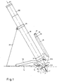
- FIG. 1 shows a projectile weapon according to the invention, in the present case a light grenade launcher in a so-called command version, in a side view
- FIG. 2 shows a plan view of the floor support element with the bottom piece of a grenade launcher designed according to the invention with the boom elements articulated to it
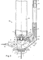
- FIGS. 3-5 each Sectional views of preferred embodiments of the projectile weapon according to the invention, here also grenade launcher with manipulation extension
- Fig. 6 is a sectional view of a grenade launcher according to the invention with ignition position indicator.
- a manipulation extension 25 which is arranged here essentially parallel to the axis A1 of the barrel 28, is connected to the latter via a transition attachment 250 in FIG by means of a manipulation element 27, which is in the form of a push button, an ignition actuation element 26 assigned to the ignition actuation device 10 1 can be moved back and forth for an arbitrary ignition device 102 (not shown here).
- the ignition actuator 26 When the ignition actuator 26 is depressed, the ignition device can be pretensioned in preparation for the fire and can be triggered for firing.
- a securing member 17 enables the weapon to be secured.
- a base plate 1 which can be detachably connected to the housing 8 of the base piece 3 here, which can be made of steel, aluminum or light metal, for example, or formed with plastic, and support plates 1 'arranged perpendicular to it.
- a mounting dome 2 for example made of hard metal, has, in the view shown, in front of and behind the weapon barrel 28 at approximately opposite locations in each case in a linkage 112 with joint 522 essentially from a position with extension to the right and left and along the weapon barrel 28 can be pivoted into a position essentially transversely to the same - pivotable cantilever elements 52 can be fixed in a frictionally locking manner - pivotable angle position.
- the broken line b denotes the floor level and shows how the visible front cantilevered cantilever element 52 is shown - this is the same for the not shown the case - lies essentially in a point shape, w uring the third edition through the base plate 1 or the mandrel 2
- the manipulation extension 25 is designed in the manner of a handle and extends so far that the horizontal position of the tube 28 can be reached by the shooter during transport and, furthermore, a carrying strap 33 which can be hooked into a eyelet 82 of the housing 8 and is connected to the other end by a clamp 29 of the weapon barrel and which optionally has a division for approximate adjustment of the leveling angle, is provided.
- Fig. 2 shows how the bottom plate 3 connected to the housing 8 bottom plate 1 has articulation bearing 112, in which to each other in the direction of the vertical direction of the weapon barrel 28 an angle ⁇ of about 300 ° including axes A2, A3, the bottom piece 3 each diametrically opposite, hollow cantilever elements 52 with joints 522 are pivotable.
- the spring 522 is pressed against the bearing 112 by means of tension bolts 50 which are variable in tension, while maintaining a frictional engagement, whereby the pivoting-up angular position of each of the boom elements 52 in relation to the weapon barrel 28 can be determined.
- tension bolts 50 which are variable in tension, while maintaining a frictional engagement, whereby the pivoting-up angular position of each of the boom elements 52 in relation to the weapon barrel 28 can be determined.
- an approximately toothing can also be provided or the like.
- Provided locking closure may be provided.
- a plastic cap 51 protects the joint 522 from dirt.
- the advantage of a frictional engagement of the joint is that when high acceleration forces, e.g. when firing, the frictional engagement is overcome, and sinking of the pipe end facing away from the muzzle with base plate 1 practically while maintaining the absolute position of the pipe axis A1, i.e. the pipe increase, so that a message after firing a shot or a shot is hardly necessary, the Support by the cantilever elements 52 remains fully intact
- the grenade launcher 100 shown here in combination with the extension elements 52, has a manipulation extension 25 connected to the housing 8 of the base piece 3 at the rear via an extension 250, a tubular actuating member 26, e.g. made of steel, aluminum or plastic, the ignition actuation mechanism, which is not visible here, can be moved and the arbitrary ignition device located in the base piece 3 or its housing 8 can be actuated.
- the housing 8 also has the suspension eyelet 82 for a carrying strap.
- FIG. 3 shows how the weapon barrel 28 of a grenade launcher 100 is screw-connected to the base piece 3 and how a housing 8 is detachably connected to the base piece by means of screw bolts 83 with head 18 via the cover 9 with the base plate 1 with cross plates 1 ', 1 is connected.
- the ignition pin 4 which is acted upon by spring 6, is arranged in an ignition pin insert 5.
- the housing 8 of the base piece 3 is via a projection 250 with a manipulation extension 25 connected, the interiors preferably merge into one another wall-tight.
- extension 25 force is applied with tension spring 23 and equipped with a manipulation button 27 at its distal end, forming an ignition actuating device 101 overall, a tubular ignition actuating member 26 which can be moved back and forth in a longitudinally slidable manner and which has a guide element 260 at its lower end, which has a - slot-like guide 130 of the relatively short rear lever arm 1 32 of a hammer 13 of the ignition device 102, which is pivotably mounted in the projection 250, slidably cooperates in constant engagement.
- a crank 19 a safety element 17 can be actuated, by means of which a movement of the hammer 13 is inhibited.
- the shooter For firing, the shooter hits the pushbutton 27 of the ignition actuating member 26 with high force, which, due to the short lever arm 132, results in a high translation to the hammer head 131, which accelerates to the muzzle-facing side of the firing pin 4 of the ignition bolt 4, as shown in broken lines Ignition device 102 strikes, whereby the force of its rear spring 6 is overcome and ignition of a projectile located in tube 28 is effected.
- the detachable buckle 34 of a carrying strap 33 can be suspended in an eyelet 82 of the housing 8.
- the cantilever elements which are preferably articulated to the base plate 1 are not shown here. Reference symbols not explained here have the same meaning as in FIGS. 1 and 2.
- FIG. 4 shows, on the basis of a section, a further embodiment of the invention, in which the hammer 13 of the ignition device 102 is tensioned and actuated separately when triggered to ignite a projectile.
- Gun barrel 28, base piece 3, its housing 8 and extension 250 are also visible here.
- a tubular manipulation member 26 with push button 27 can be moved up and down, which likewise has a guide element 260 at its lower end, which in turn has a Slot guide 460 of a pawl body 46 articulated in the extension 25, in constant engagement, smooth-cooperates.
- a striking hammer 13 can be tensioned against the force of a spring 43 supported on the cover 9 of the housing 8, as a result of which the pawl body 46 moves into a backward inclined position and its projection 461 only has a projection 133 at the edge the rear of the hammer 13 holds If the manipulation member 26 now moves towards the latch body 46, the same is pulled out of the just existing engagement with the hammer 13 and the spring-loaded hammer 13 is released, which moves with high acceleration to the firing pin 4 in Insert 5 moves so that its tip is pressed into the primer of a projectile while overcoming the force of its return spring 6.
- the safety device 17 can also be actuated here with a crank 1 9.
- a horizontal base plate 1 with vertical plate extensions 1 ′, 1 ′′ is connected to the lower cover 9 of the housing 8.
- the housing 8 also has an eyelet 82 for hanging a carrying belt.
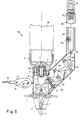
- Fig. 5 shows in section a particularly preferred embodiment of the projectile according to the invention, also a grenade launcher 100, it being noted that reference numerals not explained for this figure have the same meaning as in the previous figures.
- the projectile weapon 100 is equipped in the same way with tube 28, base piece 3, with this connected base piece - housing 8, to which in turn a base plate 1 with cross plates 1 ', 1 ", here with an interchangeable attachment dome 2, for example with hard metal or.
- the housing 8 is laterally connected via attachment 250 to the manipulation extension 25, which here also extends essentially parallel to the tube 28, in which an elongated, tubular manipulation element 26 also slides back and forth by means of manipulation button 27 against the force of a spring 23
- manipulation extension 25 is movable by means of screws 26 1 spacing from the wall of the extension 25.
- the actuating member 26 is articulated to the leg 60 of a toggle lever 65, the other leg 61 of which in turn is in the manipulation extension 25 or its Approach 250 is mounted, and articulated to itself a lever type loaded with spring 21 igen latch body 4 6, which cooperates with its distal extension 461 with a recess 133 of an approximately L-shaped, also in the approach 250 mounted and with spring 43 hammer hammer 13 can be applied.
- a locking pin 17 can be used to secure the hammer 13 against movement, for example in the position shown here.
- the actuating member 26 For triggering an ignition, the actuating member 26 is moved in the direction of the base plate 1, with the toggle lever leg 61 moving, the ratchet lever 4 6 tensioning the hammer 13 against the force of the spring 43, and then, and this is particularly advantageous in this construction only after overcoming A noticeable force threshold for the shooter releasing the hammer 13 by disengaging the ratchet lever 4 6 from the recess 133 of the hammer 1 3, after which this strikes the firing pin 4 with great acceleration on the firing pin 4 in the direction of the pipe mouth, and the primer of a projectile is fired.
- a special feature of the construction shown here is, in addition to the high level of safety which is ensured by overcoming the described force threshold between tensioning and triggering of the ignition device 1 02, the formation of the base piece housing 8 connected to the base plate 1 by means of the base plate 1 and the base part 3 by means of tie rod-like elements whose lower cover 9 is in turn an easily replaceable attachment mandrel 2, for example with a hard material tip, screw-fastened.
- This construction enables easy replacement of the attachment dome 2 and easy access to the ignition actuating device 101 and the ignition device 102 itself.
- the eyelet 82 for hanging a snap buckle 3 4 of a carrying belt 33 is also visible.
- FIG. 6 with a view of a grenade launcher 100 with arms 52 folded toward the tube 28 shows a preferred detail of the ignition device 1 02, two indicator pins 41 being arranged on both sides of the ignition pin 4 in the housing 8 of the base piece 3, which are in the front ignition position of the pin 4 as a result of this widened part 42 in its side facing away from the mouth against the force of springs 4 4 are pushed radially out through the wall of the housing 8 and thereby indicate to the shooter that the ignition pin 4 is in the ignition position.
Landscapes
- Engineering & Computer Science (AREA)
- General Engineering & Computer Science (AREA)
- Toys (AREA)
Applications Claiming Priority (2)
| Application Number | Priority Date | Filing Date | Title |
|---|---|---|---|
| AT38685A AT396991B (de) | 1985-02-11 | 1985-02-11 | Geschosswaffe, insbesondere granatwerfer |
| AT386/85 | 1985-02-11 |
Related Child Applications (2)
| Application Number | Title | Priority Date | Filing Date |
|---|---|---|---|
| EP88119451 Division | 1986-02-10 | ||
| EP88119451.8 Division-Into | 1986-02-10 |
Publications (2)
| Publication Number | Publication Date |
|---|---|
| EP0191754A2 true EP0191754A2 (fr) | 1986-08-20 |
| EP0191754A3 EP0191754A3 (fr) | 1987-07-01 |
Family
ID=3489215
Family Applications (1)
| Application Number | Title | Priority Date | Filing Date |
|---|---|---|---|
| EP86890026A Withdrawn EP0191754A3 (fr) | 1985-02-11 | 1986-02-10 | Arme à canon, notamment du type mortier |
Country Status (2)
| Country | Link |
|---|---|
| EP (1) | EP0191754A3 (fr) |
| AT (1) | AT396991B (fr) |
Cited By (3)
| Publication number | Priority date | Publication date | Assignee | Title |
|---|---|---|---|---|
| EP0219603A1 (fr) * | 1985-09-19 | 1987-04-29 | Rheinmetall GmbH | Dispositif de lancement pour munitions éclairantes |
| FR2704636A1 (fr) * | 1993-04-29 | 1994-11-04 | Sambardier Noel | Système de percussion à came. |
| CN111998725A (zh) * | 2020-10-21 | 2020-11-27 | 天津爱思达新材料科技有限公司 | 便携式巡飞弹发射筒可折叠支架结构 |
Family Cites Families (7)
| Publication number | Priority date | Publication date | Assignee | Title |
|---|---|---|---|---|
| NL6322C (fr) * | 1917-03-09 | |||
| CH184652A (de) * | 1935-08-27 | 1936-06-15 | Sykora Otakar | Granatenwerfer. |
| BE434883A (fr) * | 1938-06-15 | |||
| US2489283A (en) * | 1947-09-19 | 1949-11-29 | Us Sec War | Bipod |
| FR985171A (fr) * | 1948-06-12 | 1951-07-16 | Hausse pour bouches à feu courtes montées | |
| US3960052A (en) * | 1972-11-17 | 1976-06-01 | Smith Matthew S | Weapon arrangement |
| DE2635677A1 (de) * | 1976-08-07 | 1978-02-09 | Dynamit Nobel Ag | Abschusseinrichtung, insbesondere fuer raketen |
-
1985
- 1985-02-11 AT AT38685A patent/AT396991B/de not_active IP Right Cessation
-
1986
- 1986-02-10 EP EP86890026A patent/EP0191754A3/fr not_active Withdrawn
Cited By (3)
| Publication number | Priority date | Publication date | Assignee | Title |
|---|---|---|---|---|
| EP0219603A1 (fr) * | 1985-09-19 | 1987-04-29 | Rheinmetall GmbH | Dispositif de lancement pour munitions éclairantes |
| FR2704636A1 (fr) * | 1993-04-29 | 1994-11-04 | Sambardier Noel | Système de percussion à came. |
| CN111998725A (zh) * | 2020-10-21 | 2020-11-27 | 天津爱思达新材料科技有限公司 | 便携式巡飞弹发射筒可折叠支架结构 |
Also Published As
| Publication number | Publication date |
|---|---|
| AT396991B (de) | 1994-01-25 |
| EP0191754A3 (fr) | 1987-07-01 |
| ATA38685A (de) | 1993-05-15 |
Similar Documents
| Publication | Publication Date | Title |
|---|---|---|
| DE19925864C1 (de) | Anbau-Granatwerfer | |
| DE2442107C2 (de) | Halbautomatische Feuerwaffe | |
| EP0416642A2 (fr) | Arme à feu | |
| EP0460362A2 (fr) | Système de conversion du canon pour arme à faible recul, en particulier pour pistolets et pistolets mitrailleurs | |
| DE1095217B (de) | Bolzenschiessgeraet | |
| EP4028710A1 (fr) | Arme à feu | |
| DE1728249A1 (de) | Selbstladepistole mit Spannabzug | |
| DE1911374B2 (de) | Ausloesemechanismus fuer einen bolzenschussapparat | |
| EP0191754A2 (fr) | Arme à canon, notamment du type mortier | |
| DE2432972A1 (de) | Selbstladepistole mit dauerfeuerschaltung | |
| EP4028708B1 (fr) | Système de verrouillage | |
| DE1221112B (de) | Geraet zum Transportieren und Abschiessen von Raketen | |
| EP1241429B1 (fr) | Lanceur-grenades automatique | |
| DE2437933C3 (de) | Abzugseinrichtung an einem Brennkraftbolzensetzer | |
| DE2726991C2 (de) | Patronenhülse zum Setzen einer Bodenplatte für einen Minenwerfer | |
| DE1944625A1 (de) | An einer Handfeuerwaffe befestigbarer Granatwerfer | |
| AT505964B1 (de) | Granatwerfer | |
| DE1166052B (de) | Einsatzgeraet mit Einstecklauf zum Verschiessen von Kleinkaliber-Munition durch automatische Handfeuerwaffen, insbesondere Sturmgewehre mit Hammerzuendung | |
| DE2744403A1 (de) | Zwei- oder mehrlaeufiges gewehr | |
| DE209022C (fr) | ||
| DE10034114C1 (de) | Spielzeugschießwaffe | |
| DE294954C (fr) | ||
| EP0134775B1 (fr) | Mortier | |
| DE300077C (fr) | ||
| CH653125A5 (de) | Feuerwaffe, insbesondere handfeuerwaffe. |
Legal Events
| Date | Code | Title | Description |
|---|---|---|---|
| PUAI | Public reference made under article 153(3) epc to a published international application that has entered the european phase |
Free format text: ORIGINAL CODE: 0009012 |
|
| AK | Designated contracting states |
Kind code of ref document: A2 Designated state(s): BE CH DE FR GB IT LI LU NL SE |
|
| PUAL | Search report despatched |
Free format text: ORIGINAL CODE: 0009013 |
|
| AK | Designated contracting states |
Kind code of ref document: A3 Designated state(s): BE CH DE FR GB IT LI LU NL SE |
|
| 17P | Request for examination filed |
Effective date: 19871123 |
|
| 17Q | First examination report despatched |
Effective date: 19880725 |
|
| RAP1 | Party data changed (applicant data changed or rights of an application transferred) |
Owner name: VOEST-ALPINE STAHL AKTIENGESELLSCHAFT |
|
| RAP1 | Party data changed (applicant data changed or rights of an application transferred) |
Owner name: BOEHLER PNEUMATIK INTERNATIONAL GESELLSCHAFT M.B.H |
|
| STAA | Information on the status of an ep patent application or granted ep patent |
Free format text: STATUS: THE APPLICATION IS DEEMED TO BE WITHDRAWN |
|
| 18D | Application deemed to be withdrawn |
Effective date: 19891031 |
|
| RIN1 | Information on inventor provided before grant (corrected) |
Inventor name: MELCHER, GUENTHER |