EP0191971B1 - Roboterarm - Google Patents
Roboterarm Download PDFInfo
- Publication number
- EP0191971B1 EP0191971B1 EP85305587A EP85305587A EP0191971B1 EP 0191971 B1 EP0191971 B1 EP 0191971B1 EP 85305587 A EP85305587 A EP 85305587A EP 85305587 A EP85305587 A EP 85305587A EP 0191971 B1 EP0191971 B1 EP 0191971B1
- Authority
- EP
- European Patent Office
- Prior art keywords
- arm
- ball
- robot arm
- socket
- drive
- Prior art date
- Legal status (The legal status is an assumption and is not a legal conclusion. Google has not performed a legal analysis and makes no representation as to the accuracy of the status listed.)
- Expired
Links
Images


Classifications
-
- B—PERFORMING OPERATIONS; TRANSPORTING
- B25—HAND TOOLS; PORTABLE POWER-DRIVEN TOOLS; MANIPULATORS
- B25J—MANIPULATORS; CHAMBERS PROVIDED WITH MANIPULATION DEVICES
- B25J9/00—Program-controlled manipulators
- B25J9/02—Program-controlled manipulators characterised by movement of the arms, e.g. cartesian coordinate type
- B25J9/04—Program-controlled manipulators characterised by movement of the arms, e.g. cartesian coordinate type by rotating at least one arm, excluding the head movement itself, e.g. cylindrical coordinate type or polar coordinate type
- B25J9/048—Pendulum type
-
- B—PERFORMING OPERATIONS; TRANSPORTING
- B23—MACHINE TOOLS; METAL-WORKING NOT OTHERWISE PROVIDED FOR
- B23K—SOLDERING OR UNSOLDERING; WELDING; CLADDING OR PLATING BY SOLDERING OR WELDING; CUTTING BY APPLYING HEAT LOCALLY, e.g. FLAME CUTTING; WORKING BY LASER BEAM
- B23K11/00—Resistance welding; Severing by resistance heating
- B23K11/30—Features relating to electrodes
- B23K11/31—Electrode holders and actuating devices therefor
- B23K11/318—Supporting devices for electrode holders
-
- B—PERFORMING OPERATIONS; TRANSPORTING
- B23—MACHINE TOOLS; METAL-WORKING NOT OTHERWISE PROVIDED FOR
- B23Q—DETAILS, COMPONENTS, OR ACCESSORIES FOR MACHINE TOOLS, e.g. ARRANGEMENTS FOR COPYING OR CONTROLLING; MACHINE TOOLS IN GENERAL CHARACTERISED BY THE CONSTRUCTION OF PARTICULAR DETAILS OR COMPONENTS; COMBINATIONS OR ASSOCIATIONS OF METAL-WORKING MACHINES, NOT DIRECTED TO A PARTICULAR RESULT
- B23Q1/00—Members which are comprised in the general build-up of a form of machine, particularly relatively large fixed members
- B23Q1/01—Frames, beds, pillars or like members; Arrangement of ways
- B23Q1/017—Arrangements of ways
-
- B—PERFORMING OPERATIONS; TRANSPORTING
- B23—MACHINE TOOLS; METAL-WORKING NOT OTHERWISE PROVIDED FOR
- B23Q—DETAILS, COMPONENTS, OR ACCESSORIES FOR MACHINE TOOLS, e.g. ARRANGEMENTS FOR COPYING OR CONTROLLING; MACHINE TOOLS IN GENERAL CHARACTERISED BY THE CONSTRUCTION OF PARTICULAR DETAILS OR COMPONENTS; COMBINATIONS OR ASSOCIATIONS OF METAL-WORKING MACHINES, NOT DIRECTED TO A PARTICULAR RESULT
- B23Q1/00—Members which are comprised in the general build-up of a form of machine, particularly relatively large fixed members
- B23Q1/25—Movable or adjustable work or tool supports
- B23Q1/44—Movable or adjustable work or tool supports using particular mechanisms
- B23Q1/50—Movable or adjustable work or tool supports using particular mechanisms with rotating pairs only, the rotating pairs being the first two elements of the mechanism
- B23Q1/54—Movable or adjustable work or tool supports using particular mechanisms with rotating pairs only, the rotating pairs being the first two elements of the mechanism two rotating pairs only
- B23Q1/545—Movable or adjustable work or tool supports using particular mechanisms with rotating pairs only, the rotating pairs being the first two elements of the mechanism two rotating pairs only comprising spherical surfaces
-
- B—PERFORMING OPERATIONS; TRANSPORTING
- B25—HAND TOOLS; PORTABLE POWER-DRIVEN TOOLS; MANIPULATORS
- B25J—MANIPULATORS; CHAMBERS PROVIDED WITH MANIPULATION DEVICES
- B25J17/00—Joints
- B25J17/02—Wrist joints
- B25J17/0258—Two-dimensional joints
- B25J17/0266—Two-dimensional joints comprising more than two actuating or connecting rods
-
- B—PERFORMING OPERATIONS; TRANSPORTING
- B25—HAND TOOLS; PORTABLE POWER-DRIVEN TOOLS; MANIPULATORS
- B25J—MANIPULATORS; CHAMBERS PROVIDED WITH MANIPULATION DEVICES
- B25J9/00—Program-controlled manipulators
- B25J9/003—Program-controlled manipulators having parallel kinematics
- B25J9/0072—Program-controlled manipulators having parallel kinematics of the hybrid type, i.e. having different kinematics chains
Definitions
- This invention relates generally to robot arms and in particular to a robot arm for carrying a tool the use of which causes large mechanical forces to be transmitted back through the arm to its support.
- Typical welding impact thrust forces are in the range of 500 to 2000 lbs (227 to 907 kg) at the point of impact and it is this large force which has to be transmitted back to the base support, via the robot arm itself and the bearing at which this arm is mounted for movement.
- DE-A-3210466 there is disclosed an automated minipulator or robot arm having a ball and socket joint about which the arm is movable.
- the disclosure proposes a plurality of such ball and socket jointed arms connected serially one to another.
- such arms are moved by pairs of extensible linkages or actuators which are connected across at an angle from a point on the arm spaced from the ball joint of the arm and a fixed point adjacent the mating socket.
- robot arm apparatus includes a robot arm arrangement including a robot arm adapted to carry a tool, a ball and socket joint by means of which the arm is movably mounted and in which the ball is in direct contact with the interior surface of the socket over a spherically curved surface area which remains substantially constant irrespective of angular movement of the arm, and a drive coupling connected to the arm for effecting angular movement of the latter, characterised in that the drive coupling comprises two drive linkages one for effecting angular movement of the robot arm in one plane and the other for effecting angular movement of said arm in a plane normal to said one plane, in that each linkage includes a link which at one end is pivotally connected to the robot arm substantially along an axis normal to the direction in which in use a thrust load derived from the tool is transmitted along the arm, and in that the other end of each link is connected to an eccentric device drivable in a circular path centred at a spacing from the centre of the ball and socket joint by the length of the link.
- the path of load transmission is separated from the drive path. This enables the drive coupling to be of small dimensions as compared to the size which would be needed if the load thrust was to be transmitted therethrough. More generally, therefore, the invention avoids the requirement to use increasingly large and expensive drive transmissions according to the thrust load to which the robot arm is to be subjected.
- a preferred arrangement employs a ball formed at the end of the robot arm, seated in a socket carried by a suitable support, which could be the moving end of a primary robot arm but more typically will be a carriage mounted for linear movement.
- the link pivot point on the robot arm is spaced from the ball and socket joint, but preferably by a distance which is only a small fraction of the length of the arm to the tool.
- the length of the path of angular movement of the tool is thus considerably greater than that of the driven eccentric.
- An important feature of the invention concerns the use of a socket (at the ball and socket joint) which is formed in parts which can be relatively adjusted to enable the ball either to rotate freely therein or to be clamped in a chosen position of angular adjustment.
- the socket clamp In operation, typically in the welding of a vehicle body, for example, the socket clamp will be released, the robot arm swung to the next welding point, and the socket clamp restored prior to the welding operation.
- either a shaped anvil or an opposed tool preferably carried by a similar robot, will provide a back up for the applied thrust.
- the socket support will, in application to the welding of vehicle bodies, preferably be carried by a rectilinear carriage system which enables linear adjustment of the robot arm in three dimensions. Such a carriage system is readily designed in turn to absorb the applied thrust derived from the ball and socket joint.
- the robot arm may alternatively be carried by a primary robot arm, in turn designed to transmit the derived thrust, for example by means of a ball and socket joint in accordance with the invention.
- a spot welding apparatus incorporates a robot arm 10 for a welding tool, which as indicated and as is conventional, comprises a gun cylinder 12 and piston/ tool head 14 carrying the tool 16.
- Reference 18 denotes a power supply feeder.
- the arm 10 is formed, at the end remote from the tool head, with a ball 20 held within a socket 22 to form a ball and socket joint.
- the ball 20 is in direct contact with the interior of the spherical socket, and has a constant area of engagement therewith independently of angular movement of said robot arm 10.
- Angular movement of the robot arm is produced by drive couplings 24, 26 by which the arm can be swung in either of two mutually perpendicular planes.
- Each drive coupling 24 or 26 comprises a simple pivotal link 28 driven by an eccentric 30 to which the link is pivoted via a rose joint 32.
- the eccentric 30 is drivable along a circular arc to effect a corresponding rotational movement of the robot arm via the link.
- the drive for the eccentric 30 is produced by a d.c servo 34 associated with resolver 36, with transmission via harmonic gear box 38 ( Figure 1).
- the transmission also includes brake 40. It will be seen from Figure 3 that the link 28 is pivotal to the arm 10 at an intermediate position in the length of said arm, of the order of 1/5 to 1/4 of the length of the arm from the ball and socket joint.
- the part forming the socket of the ball and socket joint is formed in two relatively adjustable parts 42, 44.
- the ball 20, and thus the robot arm 10 can be clamped tight in the socket and freed sufficiently for angular rotation by either one of the drive couplings.
- the robot arm 10 is first unclamped, swung to a fresh operational position, and reclamped before the welding tool 16 is operated.
- the spot welding tool 16 acts on the part 46 to be welded against back-up tooling 48, which in some circumstances may alternatively consist of an opposed welding tool.
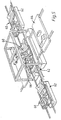
- FIG. 5 shows the layout of a welding station on an automatic guided vehicle production line.
- Reference 60 denotes the vehicle chassis, to which is being welded, for example, the transmission tunnel housing.
- the chassis units are conveyed longitudinally through the station, whereat they are temporarily unloaded from their conveying carriages 62 to enable positioning of back-up tooling on a tray 64 beneath the chassis, prior to a spot welding operation by welding apparatus 66 which is arranged in the manner previously described with reference to Figures 1 to 3, including a robot arm carried on a ball and socket joint itself carried by a linear carriageway system.
- the apparatus of the invention is especially useful also, for example, for welding inside a closed vehicle chassis (ie chassis plus roof body). Due to its compact size enabled by the ball and socket joint, it can be mounted on the end of a column mounted arm projecting into the closed chassis through a window opening.
- the invention can also be employed in fields other than welding of vehicle bodies, and even fields outside welding, in particular where a robot arm is required to carry a tool the use of which causes generation of high thrust loads which have to be transmitted through the robot arm to its support.
Landscapes
- Engineering & Computer Science (AREA)
- Mechanical Engineering (AREA)
- Robotics (AREA)
- Manipulator (AREA)
- Resistance Welding (AREA)
Claims (7)
Priority Applications (1)
| Application Number | Priority Date | Filing Date | Title |
|---|---|---|---|
| AT85305587T ATE38345T1 (de) | 1985-02-19 | 1985-08-06 | Roboterarm. |
Applications Claiming Priority (2)
| Application Number | Priority Date | Filing Date | Title |
|---|---|---|---|
| GB08504218A GB2171074B (en) | 1985-02-19 | 1985-02-19 | Improvements in robot arms |
| GB8504218 | 1985-02-19 |
Publications (2)
| Publication Number | Publication Date |
|---|---|
| EP0191971A1 EP0191971A1 (de) | 1986-08-27 |
| EP0191971B1 true EP0191971B1 (de) | 1988-11-02 |
Family
ID=10574705
Family Applications (1)
| Application Number | Title | Priority Date | Filing Date |
|---|---|---|---|
| EP85305587A Expired EP0191971B1 (de) | 1985-02-19 | 1985-08-06 | Roboterarm |
Country Status (6)
| Country | Link |
|---|---|
| EP (1) | EP0191971B1 (de) |
| JP (1) | JPS61189880A (de) |
| AT (1) | ATE38345T1 (de) |
| CA (1) | CA1258083A (de) |
| DE (1) | DE3565954D1 (de) |
| GB (1) | GB2171074B (de) |
Families Citing this family (1)
| Publication number | Priority date | Publication date | Assignee | Title |
|---|---|---|---|---|
| US4762016A (en) * | 1987-03-27 | 1988-08-09 | The Regents Of The University Of California | Robotic manipulator having three degrees of freedom |
Family Cites Families (5)
| Publication number | Priority date | Publication date | Assignee | Title |
|---|---|---|---|---|
| FR1496094A (fr) * | 1966-04-18 | 1967-09-29 | Nantaise De Fonderies Reunies | Articulation et verrouillage d'une transmission sur télé-manipulateur |
| US4636138A (en) * | 1982-02-05 | 1987-01-13 | American Robot Corporation | Industrial robot |
| DE3210466A1 (de) * | 1982-03-22 | 1983-09-29 | Peter Dipl.-Kfm. Dr. 6230 Frankfurt Gschaider | Verfahren und vorrichtung zur durchfuehrung von handhabungsprozessen |
| NO151574C (no) * | 1982-09-28 | 1986-12-30 | Ole Molaug | Boeyelig robotarm. |
| JPS59107897A (ja) * | 1982-11-10 | 1984-06-22 | リットン・ユー・ケイ・リミテッド | ブレ−キ装置 |
-
1985
- 1985-02-19 GB GB08504218A patent/GB2171074B/en not_active Expired
- 1985-08-06 EP EP85305587A patent/EP0191971B1/de not_active Expired
- 1985-08-06 DE DE8585305587T patent/DE3565954D1/de not_active Expired
- 1985-08-06 AT AT85305587T patent/ATE38345T1/de not_active IP Right Cessation
- 1985-08-23 CA CA000489279A patent/CA1258083A/en not_active Expired
-
1986
- 1986-01-23 JP JP61013628A patent/JPS61189880A/ja active Pending
Also Published As
| Publication number | Publication date |
|---|---|
| CA1258083A (en) | 1989-08-01 |
| EP0191971A1 (de) | 1986-08-27 |
| GB2171074A (en) | 1986-08-20 |
| JPS61189880A (ja) | 1986-08-23 |
| GB8504218D0 (en) | 1985-03-20 |
| ATE38345T1 (de) | 1988-11-15 |
| GB2171074B (en) | 1988-04-20 |
| DE3565954D1 (en) | 1988-12-08 |
Similar Documents
| Publication | Publication Date | Title |
|---|---|---|
| US5314293A (en) | Direct drive robotic system | |
| EP0080325B1 (de) | Kugelhandgelenk für Handhabungsroboter | |
| EP0418388B1 (de) | Waagerechter gegliederter roboter | |
| US6098260A (en) | Rivet fastening system for radial fuselage joints | |
| EP0208495A1 (de) | Mehrteiliges Gelenk für Industrieroboter | |
| US4267424A (en) | Spot welding machine for heavy-duty operations on surface contoured workpieces | |
| US4273504A (en) | Industrial robot system capable of pressure applied machining operations | |
| CN104718053B (zh) | 用于在冲压生产线中搬运工件的系统 | |
| US5611130A (en) | Multi-position rotary head apparatus | |
| US20110120245A1 (en) | Robot arm assembly | |
| CN108247255B (zh) | 用于车身输送台车的切换系统 | |
| US4618309A (en) | Mechanical handling mechanism, in particular for the loading and unloading of machine tools | |
| CN112476402A (zh) | 一种工业机器人的移动机构 | |
| US4125029A (en) | Wheeled vehicle moving apparatus | |
| SU722754A1 (ru) | Копирующий манипул тор | |
| CN115256344A (zh) | 舱内大纵深条件下大重量设备全向运载调姿平台 | |
| EP0191971B1 (de) | Roboterarm | |
| WO2024251112A1 (zh) | 一种悬臂轴组件及搬运供料车 | |
| EP0487896A1 (de) | Mehrachsige Werkzeugpositioniereinrichtung | |
| CN114430724A (zh) | 接地式载具 | |
| JP2022082090A (ja) | 作業装置 | |
| CN118929160A (zh) | 一种汽车生产线切换系统 | |
| CN115133463B (zh) | 一种汽车线束快速布线机构 | |
| US4628778A (en) | Industrial robot | |
| JPS643611B2 (de) |
Legal Events
| Date | Code | Title | Description |
|---|---|---|---|
| PUAI | Public reference made under article 153(3) epc to a published international application that has entered the european phase |
Free format text: ORIGINAL CODE: 0009012 |
|
| 17P | Request for examination filed |
Effective date: 19860520 |
|
| AK | Designated contracting states |
Kind code of ref document: A1 Designated state(s): AT BE CH DE FR GB IT LI LU NL SE |
|
| 17Q | First examination report despatched |
Effective date: 19871012 |
|
| RAP1 | Party data changed (applicant data changed or rights of an application transferred) |
Owner name: LITTON U.K. LIMITED |
|
| ITF | It: translation for a ep patent filed | ||
| GRAA | (expected) grant |
Free format text: ORIGINAL CODE: 0009210 |
|
| AK | Designated contracting states |
Kind code of ref document: B1 Designated state(s): AT BE CH DE FR IT LI LU NL SE |
|
| PG25 | Lapsed in a contracting state [announced via postgrant information from national office to epo] |
Ref country code: LI Effective date: 19881102 Ref country code: CH Effective date: 19881102 Ref country code: AT Effective date: 19881102 |
|
| REF | Corresponds to: |
Ref document number: 38345 Country of ref document: AT Date of ref document: 19881115 Kind code of ref document: T |
|
| REF | Corresponds to: |
Ref document number: 3565954 Country of ref document: DE Date of ref document: 19881208 |
|
| ET | Fr: translation filed | ||
| REG | Reference to a national code |
Ref country code: CH Ref legal event code: PL |
|
| PG25 | Lapsed in a contracting state [announced via postgrant information from national office to epo] |
Ref country code: LU Free format text: LAPSE BECAUSE OF NON-PAYMENT OF DUE FEES Effective date: 19890831 |
|
| PLBE | No opposition filed within time limit |
Free format text: ORIGINAL CODE: 0009261 |
|
| STAA | Information on the status of an ep patent application or granted ep patent |
Free format text: STATUS: NO OPPOSITION FILED WITHIN TIME LIMIT |
|
| 26N | No opposition filed | ||
| PG25 | Lapsed in a contracting state [announced via postgrant information from national office to epo] |
Ref country code: NL Effective date: 19900301 |
|
| NLV4 | Nl: lapsed or anulled due to non-payment of the annual fee | ||
| PGFP | Annual fee paid to national office [announced via postgrant information from national office to epo] |
Ref country code: DE Payment date: 19900627 Year of fee payment: 6 |
|
| PGFP | Annual fee paid to national office [announced via postgrant information from national office to epo] |
Ref country code: BE Payment date: 19900719 Year of fee payment: 6 |
|
| PGFP | Annual fee paid to national office [announced via postgrant information from national office to epo] |
Ref country code: FR Payment date: 19900727 Year of fee payment: 6 |
|
| PGFP | Annual fee paid to national office [announced via postgrant information from national office to epo] |
Ref country code: SE Payment date: 19900820 Year of fee payment: 6 |
|
| REG | Reference to a national code |
Ref country code: FR Ref legal event code: EM |
|
| PG25 | Lapsed in a contracting state [announced via postgrant information from national office to epo] |
Ref country code: SE Effective date: 19910807 |
|
| PG25 | Lapsed in a contracting state [announced via postgrant information from national office to epo] |
Ref country code: BE Effective date: 19910831 |
|
| BERE | Be: lapsed |
Owner name: LITTON U.K. LTD Effective date: 19910831 |
|
| PG25 | Lapsed in a contracting state [announced via postgrant information from national office to epo] |
Ref country code: FR Effective date: 19920430 |
|
| PG25 | Lapsed in a contracting state [announced via postgrant information from national office to epo] |
Ref country code: DE Effective date: 19920501 |
|
| REG | Reference to a national code |
Ref country code: FR Ref legal event code: ST |
|
| EUG | Se: european patent has lapsed |
Ref document number: 85305587.9 Effective date: 19920306 |