EP0192010A1 - Einrichtung und Verfahren zur Kraftstoffeinspritzung in eine Brennkraftmaschine mit Hilfe von Druckluft oder -gas - Google Patents
Einrichtung und Verfahren zur Kraftstoffeinspritzung in eine Brennkraftmaschine mit Hilfe von Druckluft oder -gas Download PDFInfo
- Publication number
- EP0192010A1 EP0192010A1 EP85402643A EP85402643A EP0192010A1 EP 0192010 A1 EP0192010 A1 EP 0192010A1 EP 85402643 A EP85402643 A EP 85402643A EP 85402643 A EP85402643 A EP 85402643A EP 0192010 A1 EP0192010 A1 EP 0192010A1
- Authority
- EP
- European Patent Office
- Prior art keywords
- pipe
- injection
- cylinder
- exhaust
- cylinders
- Prior art date
- Legal status (The legal status is an assumption and is not a legal conclusion. Google has not performed a legal analysis and makes no representation as to the accuracy of the status listed.)
- Ceased
Links
- 238000002347 injection Methods 0.000 title claims abstract description 79
- 239000007924 injection Substances 0.000 title claims abstract description 79
- 239000000446 fuel Substances 0.000 title claims abstract description 24
- 238000000034 method Methods 0.000 title claims abstract description 13
- 238000002485 combustion reaction Methods 0.000 title claims description 7
- 238000004891 communication Methods 0.000 claims description 19
- 230000007423 decrease Effects 0.000 claims description 4
- 210000000056 organ Anatomy 0.000 claims description 2
- 239000007789 gas Substances 0.000 description 20
- 239000000203 mixture Substances 0.000 description 9
- 230000000694 effects Effects 0.000 description 7
- MWUXSHHQAYIFBG-UHFFFAOYSA-N Nitric oxide Chemical compound O=[N] MWUXSHHQAYIFBG-UHFFFAOYSA-N 0.000 description 3
- 230000009467 reduction Effects 0.000 description 3
- 238000005507 spraying Methods 0.000 description 3
- 235000014676 Phragmites communis Nutrition 0.000 description 1
- 230000009471 action Effects 0.000 description 1
- 230000006835 compression Effects 0.000 description 1
- 238000007906 compression Methods 0.000 description 1
- 239000003344 environmental pollutant Substances 0.000 description 1
- 230000007246 mechanism Effects 0.000 description 1
- 231100000719 pollutant Toxicity 0.000 description 1
- 230000008569 process Effects 0.000 description 1
- 238000011084 recovery Methods 0.000 description 1
- 238000010408 sweeping Methods 0.000 description 1
- 230000001960 triggered effect Effects 0.000 description 1
Images


Classifications
-
- F—MECHANICAL ENGINEERING; LIGHTING; HEATING; WEAPONS; BLASTING
- F02—COMBUSTION ENGINES; HOT-GAS OR COMBUSTION-PRODUCT ENGINE PLANTS
- F02M—SUPPLYING COMBUSTION ENGINES IN GENERAL WITH COMBUSTIBLE MIXTURES OR CONSTITUENTS THEREOF
- F02M69/00—Low-pressure fuel-injection apparatus ; Apparatus with both continuous and intermittent injection; Apparatus injecting different types of fuel
- F02M69/10—Low-pressure fuel-injection apparatus ; Apparatus with both continuous and intermittent injection; Apparatus injecting different types of fuel peculiar to scavenged two-stroke engines, e.g. injecting into crankcase-pump chamber
-
- F—MECHANICAL ENGINEERING; LIGHTING; HEATING; WEAPONS; BLASTING
- F02—COMBUSTION ENGINES; HOT-GAS OR COMBUSTION-PRODUCT ENGINE PLANTS
- F02B—INTERNAL-COMBUSTION PISTON ENGINES; COMBUSTION ENGINES IN GENERAL
- F02B13/00—Engines characterised by the introduction of liquid fuel into cylinders by use of auxiliary fluid
- F02B13/10—Use of specific auxiliary fluids, e.g. steam, combustion gas
-
- F—MECHANICAL ENGINEERING; LIGHTING; HEATING; WEAPONS; BLASTING
- F02—COMBUSTION ENGINES; HOT-GAS OR COMBUSTION-PRODUCT ENGINE PLANTS
- F02M—SUPPLYING COMBUSTION ENGINES IN GENERAL WITH COMBUSTIBLE MIXTURES OR CONSTITUENTS THEREOF
- F02M67/00—Apparatus in which fuel-injection is effected by means of high-pressure gas, the gas carrying the fuel into working cylinders of the engine, e.g. air-injection type
- F02M67/02—Apparatus in which fuel-injection is effected by means of high-pressure gas, the gas carrying the fuel into working cylinders of the engine, e.g. air-injection type the gas being compressed air, e.g. compressed in pumps
-
- F—MECHANICAL ENGINEERING; LIGHTING; HEATING; WEAPONS; BLASTING
- F02—COMBUSTION ENGINES; HOT-GAS OR COMBUSTION-PRODUCT ENGINE PLANTS
- F02M—SUPPLYING COMBUSTION ENGINES IN GENERAL WITH COMBUSTIBLE MIXTURES OR CONSTITUENTS THEREOF
- F02M67/00—Apparatus in which fuel-injection is effected by means of high-pressure gas, the gas carrying the fuel into working cylinders of the engine, e.g. air-injection type
- F02M67/06—Apparatus in which fuel-injection is effected by means of high-pressure gas, the gas carrying the fuel into working cylinders of the engine, e.g. air-injection type the gas being other than air, e.g. steam, combustion gas
-
- F—MECHANICAL ENGINEERING; LIGHTING; HEATING; WEAPONS; BLASTING
- F02—COMBUSTION ENGINES; HOT-GAS OR COMBUSTION-PRODUCT ENGINE PLANTS
- F02M—SUPPLYING COMBUSTION ENGINES IN GENERAL WITH COMBUSTIBLE MIXTURES OR CONSTITUENTS THEREOF
- F02M69/00—Low-pressure fuel-injection apparatus ; Apparatus with both continuous and intermittent injection; Apparatus injecting different types of fuel
- F02M69/08—Low-pressure fuel-injection apparatus ; Apparatus with both continuous and intermittent injection; Apparatus injecting different types of fuel characterised by the fuel being carried by compressed air into main stream of combustion-air
-
- F—MECHANICAL ENGINEERING; LIGHTING; HEATING; WEAPONS; BLASTING
- F02—COMBUSTION ENGINES; HOT-GAS OR COMBUSTION-PRODUCT ENGINE PLANTS
- F02B—INTERNAL-COMBUSTION PISTON ENGINES; COMBUSTION ENGINES IN GENERAL
- F02B75/00—Other engines
- F02B75/02—Engines characterised by their cycles, e.g. six-stroke
- F02B2075/022—Engines characterised by their cycles, e.g. six-stroke having less than six strokes per cycle
- F02B2075/025—Engines characterised by their cycles, e.g. six-stroke having less than six strokes per cycle two
Definitions
- the present invention relates to a device and a method allowing and / or improving the injection of fuel assisted by air or compressed gases, or pneumatic injection on an internal combustion engine.
- the present invention can be applied to four-stroke engines and two-stroke engines, in particular those with air sweeping.
- the device according to the invention uses the pressure wave effects prevailing in the exhaust pipes to assist in pneumatic injection. This results in a better quality of the pneumatic injection, an increase in the air filling of the engine, an increase in the quantity of residual gases burned, hence a reduction in nitrogen oxide emissions, a partial recovery of the short fuel. -exhaust circuitry and possible reduction of noise due to the effects of exhaust pressure waves.
- the present invention relates to an internal combustion engine comprising a pneumatic fuel injection member, an exhaust manifold. It is characterized in that the engine comprises a pipe which will be called auxiliary having two ends or openings, one being connected to said exhaust pipe and the other to said injection member.
- the engine may include a pump casing and a chamber connecting the pump casing to the injection member, this chamber constituting an injection chamber, an auxiliary pipe connecting the exhaust pipe to said injection chamber, and this chamber injection may include an obstruction member, such as a non-return valve or valve, this member being located before the connection of the auxiliary pipe to the injection chamber.
- an obstruction member such as a non-return valve or valve
- the auxiliary pipe may include an obstruction member such as a non-return valve or valve, this member opening intermittently due to a mechanical control such as a cam, pneumatic, electropneumatic, etc.
- an obstruction member such as a non-return valve or valve, this member opening intermittently due to a mechanical control such as a cam, pneumatic, electropneumatic, etc.
- the auxiliary pipe has a third opening leading to a gas source and an obstruction member placed on said opening such as a non-return valve or valve.
- the end of the auxiliary pipe connected to the exhaust pipe may preferably be positioned on this pipe at a place where the pressure wave is maximum.
- the end of the auxiliary pipe connected to the exhaust pipe may have the shape of a convergent whose section decreases going from the exhaust manifold to the auxiliary pipe.
- the present invention can be applied to an engine comprising at least two cylinders, each of which comprises a pipe and an injection member.
- the engine may also include at least one cross auxiliary pipe, connecting the exhaust pipe of one of the cylinders to the injection member of the other cylinder.
- the present invention can be applied to an engine comprising at least two cylinders, each of which comprises an exhaust pipe, an injection member and an injection chamber connected to the injection member of one of the cylinders, or cylinder considered.
- the engine may also include at least one cross auxiliary pipe, connecting said injection chamber to the exhaust pipe of the other cylinder.
- the engine may comprise at least one injection chamber connecting said pump casing to the injection member of the cylinder in question and the crossed auxiliary pipe may connect the exhaust manifold from the other cylinder to the injection chamber of the cylinder in question.
- the present invention can be applied to an engine comprising at least two cylinders, each of these cylinders having an exhaust manifold and an injection member.
- the engine may also comprise at least two crossed auxiliary pipes, each of them connecting the exhaust pipe of one of the cylinders to the injection member of the other cylinder.
- the present invention can be applied to an engine comprising several cylinders, at least one of which comprises an exhaust pipe and the other a pneumatic member.
- an auxiliary pipe can connect the exhaust pipe to the pneumatic injection member.
- this engine is an engine whose cylinders include a pump casing, it may also include at least two injection chambers, each of which connects the pump casing of one of the cylinders, or cylinder in question, to the member d injection of the same cylinder and each of the auxiliary pipes can connect the exhaust pipe of the other cylinder to the injection chamber connected to the injection member of the cylinder in question.
- the present invention can be applied to an engine comprising at least two cylinders, at least one of which comprises a pump housing.
- the engine may include at least one so-called crossed injection chamber connecting said pump casing to the injection member of the other cylinder.
- this other cylinder has an exhaust pipe and an auxiliary pipe connects the exhaust pipe of this other cylinder to the cross-injection chamber connected to the injection of this same cylinder.
- the present invention can be applied to an engine having at least two cylinders each equipped with a pump housing.
- the engine may comprise at least two crossed injection chambers, each of them connecting the pump housing of one of the cylinders to the injection member of the other cylinder.
- the engine comprises at least two auxiliary pipes, each of them connecting the exhaust pipe of one of the cylinders, or cylinder considered, to the injection chamber connected to the injection member of the same cylinder.
- the present invention allows numerous combinations of communications between the exhaust pipes of the different cylinders and the injection members, as well as between the pump casings and the injection members. .
- the engine comprises an exhaust manifold or if it comprises a common injection chamber communicating with several pump casings and at least one injection member.
- the engine comprises an exhaust manifold or if it comprises a common injection chamber communicating with several pump casings and at least one injection member.
- an auxiliary pipe is connected to an injection member via, or not, the common injection chamber.
- the injection chamber may consist of a pipe, this is also a preferred embodiment.
- the present invention also relates to a method for performing the injection of fuel into an internal combustion engine equipped with a pneumatic injection member and an exhaust pipe. This method is characterized in that communication is established between the exhaust pipe and the injection member.
- This process can be applied to an engine comprising a pump casing.
- part of the compressed gases coming from the pump casing is directed towards the injection member and combines with the gases coming from the communication between the exhaust and the injection member.
- the communication is brought into contact with a gas source via an obstruction member such as a non-return valve.
- an obstruction member such as a non-return valve.
- each of said cylinders comprises a pump casing and a transfer duct
- a portion of the compressed gases coming from the pump casing of said cylinder considered may be directed to the injection member of this same cylinder and combine with the gases coming from the communication between the exhaust pipe of the other cylinder to the injection member of the cylinder in question.
- a portion of the compressed gases originating from the pump casings may be directed to the injection member from another cylinder.
- the communication can connect the exhaust manifold of this other cylinder to the injection member of this same cylinder and at least part of the compressed gases coming from said pump casing can be directed towards the injection member and combines with the gases coming from the communication.
- Figure 1 is a schematic representation of a cylinder of a two-stroke engine with fuel injection assisted by compressed air and equipped with a device according to the invention.
- the reference 1 designates the cylinder closed at its upper part by the cylinder head 2 and which communicates at its lower part with a sealed casing 3.
- Lights 9 made in the wall of the cylinder 1 allow the introduction of air into the cylinder. These lights 9 communicate with the sealed casing 3 through the transfer channel 10.
- Lights 7 and 9 have the arrangement and dimensions known in the art to ensure efficient filling of the cylinder and as complete evacuation of the burnt gases.
- the casing 3 is provided with an air intake orifice 11 equipped with a valve shown diagrammatically in 11 a and which is, for example, a blade valve.
- the orifice 11 is connected to an air filter, not shown.
- the valve 11a is open and allows air to enter the casing 3 when the pressure in the casing is less than the pressure of the supply air.
- the valve 11 a closes as soon as the pressure in the casing 3 is greater than the pressure of the supply air.
- the casing 3 communicates with a sealed chamber 17 of volume V through an orifice 18 equipped with a valve 19 such as a blade valve.
- the valve 19 opens to put the chamber 17 in communication with the rest of the casing when the pressure in the chamber 17 is lower than the pressure prevailing in the rest of the casing.
- the valve closes, isolating the chamber 17 from the rest of the housing, when the pressure in the chamber 17 is greater than the pressure prevailing in the rest of the housing.
- a pneumatic fuel injection member - shown diagrammatically at 12 makes it possible to introduce into the cylinder 1 a mixture of carburetted air under pressure.
- the member 12 is connected to a fuel supply pipe 13 and to a compressed air and / or compressed gas supply pipe 14 which communicates with the chamber 17. This member and its control means will be described in detail below.
- the cylinder head 2 also carries a spark plug 15 whose electrical supply circuit has not been shown.
- the device according to the invention comprises an auxiliary tube or pipe 20 connecting the exhaust pipe 16 with the sealed chamber 17, the communication between the tube 20 and the sealed chamber 17 being made through an orifice 21 fitted with a valve 22 such than a reed valve.
- the valve 22 opens to put the tube 20 in communication with the sealed chamber 17 when the pressure in the tube is greater than the pressure prevailing in the sealed chamber.
- the valve 22 closes, isolating the chamber 1 7 from the tube 20, when the pressure in the chamber is greater than that prevailing in the tube 20.
- the piston 4 has reached the upper dead bridge by moving towards the cylinder head 2.
- the intake 9 and exhaust 7 ports are closed by the piston 4, the valve 11 a is open letting the air in the casing through the orifice 11.
- the valve 19 is closed.
- the valve 22 is closed.
- the length of tube 20 can be calculated in such a way that the positive exhaust pressure wave arrives at the orifice 21 to fill the chamber 17 after the opening of the transfer lights 9, that is to say when the casing 3 has finished supplying the chamber 17 so as not to disturb or reduce this supply, this is particularly true when there is a delay between the opening of the transfer light relative to the opening of the exhaust lights.
- the shape of the tube 20 is studied to promote the wave effect. This can be a tube whose curvature is regular and may also include sudden or gradual changes in section, for example in the form of diverging or converging cones.
- the member 12 when the member 12 is actuated, it is supplied with air and exhaust gas through the pipe 1 4 at a maximum pressure.
- the instant of introduction of the fuel mixture under pressure is determined by the adjustment of the control means of the member 12 so that there is practically no loss of fuel mixture by the exhaust ports, the pressure of supply to the injector at this time being greater than that prevailing in the cylinder.
- the exact location of the member 12 on the cylinder head 2 or the transfer channel 10, or the cylinder will be determined by the technician so that the quantity of fuel mixture escaping through the ports 7 before you burn it is zero or as low as possible.
- the same device can also operate and give sufficient pressure for injection by eliminating the communication 18, the chamber 17 and the valves 1 9 (Fig. 1A).
- a variant of the device consists in adding to the complete engine previously described on the tube 20 a short tube 23 opening into the open air or into an air filter through the orifice 24 or into a gas source such as, for example, a source fuel mixture.
- the orifice is equipped with a valve 25 which can for example be a blade valve (FIG. 8).
- the same device can also operate by eliminating the sealed chamber 17 and the opening 18 (FIG. 8A).
- the location 26 (whether in the case of FIG. 1 as well as in that of FIGS. 8 and 8A) of the connection of the tube 20 on the exhaust manifold 16 is judiciously chosen to obtain a sufficient wave effect.
- An example of such a device can be a butterfly 27 placed just after connection 26 in the pipe 16 6 (Fig. 9) whose opening angle can be corrected according to the operating characteristics of the engine.
- FIG. 9 Another example concerning the configuration of the pipe would be to give a form of convergent 26a (FIG. 9) to the pipe 20 at the connection 26 to the exhaust manifold, this convergent having a section which decreases going from the manifold d exhaust 16 to line 20.
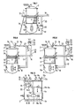
- a sealed chamber per cylinder this is the case in FIGS. 10, 11 and 12, or on the contrary common to different cylinders.
- the sealed chambers 17, 17a, 17b Evou 1 7c may be supplied by the casing 3, 3a, 3b and / or 3c of the cylinder in which they inject air case of Figures 12 and optionally one or contrary by the casing of one of the other cylinders, in the case of FIGS. 10 and 11.
- each tube 20 according to the invention corresponding to the injection into a cylinder could in fact be connected - (communication 26) to the tubing exhaust 16 of the same cylinder, case of FIGS. 10, 11 and possibly 1, as well as that of a different cylinder, case of FIG. 12.
- An example of a particular application could be, in the case of a multi-cylinder, to have the sealed chamber inflated by the casing of another cylinder and the exhaust communicating with the sealed chamber used for injection into its own cylinder.
- a very short tube 20 may be sufficient since it is no longer essential for the positive wave to arrive after the opening of the transfer lights.
- Figures 10 and 11 therefore show such applications to 2 and 3 cylinder engines.
- the principle can be generalized to engines with a higher number of cylinders.
- each cylinder has its individual sealed chamber supplied by its own casing and by a tube 20 coming from the exhaust of one of the other cylinders.
- FIG. 12A represents a more general case than that of FIG. 12.
- the communications 18a and 19a with the pump casing as well as the lower part of the sealed chamber 17 have been eliminated, only one remains.
- This communication pipe which corresponds to what has been previously designated by auxiliary pipe, may or may not include a non-return valve 22.
- Figure 13 shows the case of a chamber 1 7 'connected to two different pump casings 3 and 3a.
- This chamber is extended by a pipe 17a 'up to a spraying member 12. Furthermore, this pipe is connected to an exhaust pipe 17a' by an auxiliary pipe 20.
- the chamber 17 ′ can be connected to one or more spraying members.
Landscapes
- Engineering & Computer Science (AREA)
- Chemical & Material Sciences (AREA)
- Combustion & Propulsion (AREA)
- Mechanical Engineering (AREA)
- General Engineering & Computer Science (AREA)
- Fuel-Injection Apparatus (AREA)
- Exhaust Gas After Treatment (AREA)
- Exhaust Silencers (AREA)
Applications Claiming Priority (2)
| Application Number | Priority Date | Filing Date | Title |
|---|---|---|---|
| FR8420059 | 1984-12-28 | ||
| FR8420059A FR2575523B1 (fr) | 1984-12-28 | 1984-12-28 | Dispositif et procede d'injection de carburant assiste par air ou gaz comprime dans un moteur |
Publications (1)
| Publication Number | Publication Date |
|---|---|
| EP0192010A1 true EP0192010A1 (de) | 1986-08-27 |
Family
ID=9311121
Family Applications (2)
| Application Number | Title | Priority Date | Filing Date |
|---|---|---|---|
| EP85402629A Expired - Lifetime EP0189716B1 (de) | 1984-12-28 | 1985-12-24 | Einrichtung zur Kraftstoffeinspritzung in eine Brennkraftmaschine mit Hilfe von Druckluft oder -gas |
| EP85402643A Ceased EP0192010A1 (de) | 1984-12-28 | 1985-12-27 | Einrichtung und Verfahren zur Kraftstoffeinspritzung in eine Brennkraftmaschine mit Hilfe von Druckluft oder -gas |
Family Applications Before (1)
| Application Number | Title | Priority Date | Filing Date |
|---|---|---|---|
| EP85402629A Expired - Lifetime EP0189716B1 (de) | 1984-12-28 | 1985-12-24 | Einrichtung zur Kraftstoffeinspritzung in eine Brennkraftmaschine mit Hilfe von Druckluft oder -gas |
Country Status (5)
| Country | Link |
|---|---|
| US (3) | US4628888A (de) |
| EP (2) | EP0189716B1 (de) |
| JP (2) | JPH0816472B2 (de) |
| DE (1) | DE3585522D1 (de) |
| FR (1) | FR2575523B1 (de) |
Cited By (8)
| Publication number | Priority date | Publication date | Assignee | Title |
|---|---|---|---|---|
| EP0235481A1 (de) * | 1985-12-30 | 1987-09-09 | Institut Français du Pétrole | Vorrichtung zum Einlass von Druckgasen in den Brennraum einer Brennkraftmaschine |
| EP0296969A1 (de) * | 1987-06-26 | 1988-12-28 | Institut Français du Pétrole | Vorrichtung zum Zuführen unter Druck von einem Gemisch in den Zylinder eines Motors |
| EP0311499A1 (de) * | 1987-10-07 | 1989-04-12 | Institut Français du Pétrole | Zweitaktbrennkraftmaschine mit pneumatischer Einspritzung und Auspuffströmungsdrosselung |
| EP0266610A3 (en) * | 1986-11-07 | 1989-07-26 | Walbro Corporation (Corporation Of Delaware) | Combustion enhancer for internal combustion engines |
| EP0346188A1 (de) * | 1988-06-08 | 1989-12-13 | Institut Français du Pétrole | Vorrichtung und Verfahren für die Zufuhr von Druckluft Kraftstoff-Gemisch in den Zylinder einer Brennkraftmaschine |
| FR2662213A1 (fr) * | 1990-05-21 | 1991-11-22 | Inst Francais Du Petrole | Procede d'injection pneumatique de carburant dans un moteur a deux temps et moteur a deux temps correspondant. |
| EP0458670A1 (de) * | 1990-05-21 | 1991-11-27 | Institut Français du Pétrole | Verfahren zur pneumatischen Kraftstoffeinpritzung in einen Zweitaktmotor und ein solcher Zweitaktmotor |
| EP0189716B1 (de) * | 1984-12-28 | 1992-03-04 | Institut Français du Pétrole | Einrichtung zur Kraftstoffeinspritzung in eine Brennkraftmaschine mit Hilfe von Druckluft oder -gas |
Families Citing this family (36)
| Publication number | Priority date | Publication date | Assignee | Title |
|---|---|---|---|---|
| JPS58160520A (ja) * | 1981-12-31 | 1983-09-24 | オ−ビタル・エンジン・カンパニイ・プロプライエタリ・リミテツド | 内燃機関用燃料噴射装置 |
| ES8707782A1 (es) * | 1985-05-24 | 1987-08-16 | Orbital Eng Pty | Un metodo y un aparato para entregar combustible liquido a un motor de combustion interna. |
| ES2002842A6 (es) * | 1985-10-14 | 1988-10-01 | Orbital Eng Pty | Un metodo y un aparato para suministrar combustible a un motor de combustion interna |
| JPS6388268A (ja) * | 1986-09-23 | 1988-04-19 | オービタル、エンジン、カンパニー、プロプライエタリ、リミテッド | 内燃機関に燃料を噴射する方法及びその方法を実施する装置 |
| US4781164A (en) * | 1986-09-23 | 1988-11-01 | Orbital Engine Company Proprietary Limited | Fuel injection systems for internal combustion engines |
| US4771754A (en) * | 1987-05-04 | 1988-09-20 | General Motors Corporation | Pneumatic direct cylinder fuel injection system |
| US4794901A (en) * | 1987-06-16 | 1989-01-03 | Industrial Technology Research Institute | Low pressure air assisted fuel injection apparatus for engine |
| US4765304A (en) * | 1987-10-26 | 1988-08-23 | Outboard Marine Corporation | Internal combustion engine with compressed air collection system |
| FR2622250B1 (fr) * | 1987-10-26 | 1994-04-15 | Outboard Marine Corp | Moteur a combustion interne a reseau collecteur d'air comprime |
| FR2623854B1 (fr) * | 1987-11-27 | 1992-11-27 | Inst Francais Du Petrole | Dispositif d'injection pneumatique de carburant dans un cylindre d'un moteur a combustion interne |
| FR2625532B1 (fr) * | 1987-12-30 | 1993-04-23 | Inst Francais Du Petrole | Procede d'injection pneumatique de carburant dans un cylindre d'un moteur alternatif a combustion interne et dispositif d'injection correspondant |
| US4862857A (en) * | 1988-02-12 | 1989-09-05 | Outboard Marine Corporation | Fuel injection system for multi cylinder two-stroke engine |
| JPH02294518A (ja) * | 1989-05-02 | 1990-12-05 | Nissan Motor Co Ltd | 2ストロークエンジン |
| FR2649157A1 (fr) * | 1989-06-28 | 1991-01-04 | Inst Francais Du Petrole | Moteurs a deux temps a injection pneumatique et a restriction de debit dans au moins un conduit de transfert |
| FR2649158A1 (fr) * | 1989-06-30 | 1991-01-04 | Inst Francais Du Petrole | Dispositif de controle de debut d'introduction sous pression du melange carbure dans un moteur a combustion interne et son application au moteur 2 temps |
| JP2761412B2 (ja) * | 1989-10-17 | 1998-06-04 | 三信工業株式会社 | 筒内噴射式内燃機関 |
| GB2287507A (en) * | 1994-03-09 | 1995-09-20 | Ford Motor Co | I.c.engine compressed gas supply |
| FR2722245B1 (fr) | 1994-07-08 | 1996-08-23 | Inst Francais Du Petrole | Moteur a combustion interne ayant un reservoir de stockage de pression d'utilisation specifique |
| GB2304811A (en) * | 1995-08-26 | 1997-03-26 | Ford Motor Co | Engine intake fuel atomisation |
| JPH0996256A (ja) * | 1995-10-03 | 1997-04-08 | Nippon Soken Inc | Egrガスアシスト噴射システム |
| DE19716406A1 (de) * | 1996-04-19 | 1997-10-30 | Futaba Denshi Kogyo Kk | Kraftstoffeinspritzvorrichtung für Modellmotoren |
| US5662083A (en) * | 1996-10-09 | 1997-09-02 | Chrysler Corporation | Metering device for air assisted fuel injection |
| JP3852142B2 (ja) * | 1996-10-24 | 2006-11-29 | いすゞ自動車株式会社 | 排気還流装置 |
| US6079379A (en) * | 1998-04-23 | 2000-06-27 | Design & Manufacturing Solutions, Inc. | Pneumatically controlled compressed air assisted fuel injection system |
| DE69914483T2 (de) | 1998-06-30 | 2004-11-25 | Siemens Vdo Automotive Inc., Chatham | Abgasrückführungsventil und abgasrückführungsverfahren |
| US6273037B1 (en) | 1998-08-21 | 2001-08-14 | Design & Manufacturing Solutions, Inc. | Compressed air assisted fuel injection system |
| US6293235B1 (en) | 1998-08-21 | 2001-09-25 | Design & Manufacturing Solutions, Inc. | Compressed air assisted fuel injection system with variable effective reflection length |
| DE19838843A1 (de) * | 1998-08-27 | 2000-02-03 | Daimler Chrysler Ag | Brennstoffzuführsystem für eine fremdgezündete Brennkraftmaschine und Verfahren zum Betrieb des Brennstoffzuführsystems |
| US6367461B1 (en) * | 2000-07-07 | 2002-04-09 | Yuan-Tang Wu | Exhaust recirculating device, for a motor engine |
| KR20020081526A (ko) * | 2001-04-18 | 2002-10-28 | 한국기계연구원 | 내연기관의 배기가스 보조 연료분사 장치 |
| US20070026763A1 (en) * | 2002-01-14 | 2007-02-01 | Panec Don J | Actuatable toys containing deformable bladders |
| WO2005099364A2 (en) | 2004-04-07 | 2005-10-27 | Mack Trucks, Inc. | Emission control for an internal combustion engine |
| CA2625734C (en) * | 2005-10-14 | 2013-02-19 | Applied Medical Resources Corporation | Method of making a hand access laparoscopic device |
| US7487758B1 (en) | 2006-09-12 | 2009-02-10 | Dedenbear Products, Inc. | Control apparatus for a throttle stop of an internal combustion engine |
| DE102010008063A1 (de) * | 2010-02-16 | 2011-08-18 | WABCO GmbH, 30453 | Druckluftkompressor und Verfahren zum Betrieb eines Druckluftkompressors |
| KR101251528B1 (ko) * | 2011-09-29 | 2013-04-05 | 현대자동차주식회사 | 2기통 엔진의 서지 방지 구조 |
Citations (3)
| Publication number | Priority date | Publication date | Assignee | Title |
|---|---|---|---|---|
| GB572080A (en) * | 1944-03-06 | 1945-09-21 | Rover Co Ltd | Improvements relating to fuel injection systems for internal combustion engines |
| DE833885C (de) * | 1944-02-17 | 1952-03-13 | Rover Co Ltd | Einspritzvorrichtung fuer den fluessigen Brennstoff von Brennkraftmaschinen |
| FR2292111A1 (fr) * | 1974-11-25 | 1976-06-18 | Politechnika Krakowska | Moteur a combustion interne a deux temps a plusieurs cylindres avec injection sans pompe du carburant et allumage par bougie |
Family Cites Families (18)
| Publication number | Priority date | Publication date | Assignee | Title |
|---|---|---|---|---|
| FR490166A (fr) * | 1917-11-20 | 1919-04-05 | Jean Alexandre Culmann | Moteur à explosion fonctionnant à l'essence ou au pétrole |
| US1551731A (en) * | 1923-01-29 | 1925-09-01 | James A Charter | Fuel automizer |
| US3190271A (en) * | 1964-01-27 | 1965-06-22 | Mcculloch Corp | Fuel-air injection system for internal combustion engines |
| JPS4836510A (de) * | 1971-09-13 | 1973-05-30 | ||
| JPS4882222A (de) * | 1972-02-07 | 1973-11-02 | ||
| US3894520A (en) * | 1974-03-13 | 1975-07-15 | Thermo Electron Corp | Charge forming device with fuel vaporization |
| PL97947B3 (pl) * | 1974-06-18 | 1978-03-30 | Politechnika Krakowska | Silnik spalinowy czterosuwowy wielocylindrowy z bezpompowym wtryskiem paliwa z zaplonem iskrowym |
| JPS51109316U (de) * | 1975-02-28 | 1976-09-03 | ||
| US3996906A (en) * | 1975-04-24 | 1976-12-14 | General Motors Corporation | Controlled exhaust gas fuel atomizing nozzle |
| JPS5546509A (en) * | 1978-09-28 | 1980-04-01 | Agency Of Ind Science & Technol | Method of manufacturing solar battery |
| DE2919661A1 (de) * | 1979-05-16 | 1980-11-27 | Basf Ag | Verfahren zur vernichtung von phosgen |
| DE2936426A1 (de) * | 1979-09-08 | 1981-04-02 | Robert Bosch Gmbh, 7000 Stuttgart | Kraftstoffeinspritzventil |
| JPS6027828Y2 (ja) * | 1980-01-31 | 1985-08-22 | 株式会社小松製作所 | 内燃機関 |
| US4453502A (en) * | 1980-06-27 | 1984-06-12 | Cornell Research Foundation, Inc. | Combustion control by prestratification |
| FR2496757B1 (fr) * | 1980-12-22 | 1985-07-19 | Inst Francais Du Petrole | Dispositif pour alimenter en melange carbure un moteur deux temps avec introduction d'air a travers le carter |
| JPS57168769U (de) * | 1981-04-20 | 1982-10-23 | ||
| US4516551A (en) * | 1982-12-16 | 1985-05-14 | Toyota Jidosha Kabushiki Kaisha | Control system for ignition timing and exhaust gas recirculation of combustion engine |
| FR2575523B1 (fr) * | 1984-12-28 | 1989-04-07 | Inst Francais Du Petrole | Dispositif et procede d'injection de carburant assiste par air ou gaz comprime dans un moteur |
-
1984
- 1984-12-28 FR FR8420059A patent/FR2575523B1/fr not_active Expired
-
1985
- 1985-12-24 DE DE8585402629T patent/DE3585522D1/de not_active Expired - Lifetime
- 1985-12-24 EP EP85402629A patent/EP0189716B1/de not_active Expired - Lifetime
- 1985-12-27 JP JP60299787A patent/JPH0816472B2/ja not_active Expired - Lifetime
- 1985-12-27 JP JP60299786A patent/JPH0660610B2/ja not_active Expired - Fee Related
- 1985-12-27 EP EP85402643A patent/EP0192010A1/de not_active Ceased
- 1985-12-30 US US06/814,882 patent/US4628888A/en not_active Expired - Lifetime
- 1985-12-30 US US06/814,767 patent/US4716877A/en not_active Expired - Lifetime
-
1987
- 1987-07-09 US US07/071,357 patent/US4796594A/en not_active Expired - Lifetime
Patent Citations (3)
| Publication number | Priority date | Publication date | Assignee | Title |
|---|---|---|---|---|
| DE833885C (de) * | 1944-02-17 | 1952-03-13 | Rover Co Ltd | Einspritzvorrichtung fuer den fluessigen Brennstoff von Brennkraftmaschinen |
| GB572080A (en) * | 1944-03-06 | 1945-09-21 | Rover Co Ltd | Improvements relating to fuel injection systems for internal combustion engines |
| FR2292111A1 (fr) * | 1974-11-25 | 1976-06-18 | Politechnika Krakowska | Moteur a combustion interne a deux temps a plusieurs cylindres avec injection sans pompe du carburant et allumage par bougie |
Cited By (11)
| Publication number | Priority date | Publication date | Assignee | Title |
|---|---|---|---|---|
| EP0189716B1 (de) * | 1984-12-28 | 1992-03-04 | Institut Français du Pétrole | Einrichtung zur Kraftstoffeinspritzung in eine Brennkraftmaschine mit Hilfe von Druckluft oder -gas |
| EP0235481A1 (de) * | 1985-12-30 | 1987-09-09 | Institut Français du Pétrole | Vorrichtung zum Einlass von Druckgasen in den Brennraum einer Brennkraftmaschine |
| EP0266610A3 (en) * | 1986-11-07 | 1989-07-26 | Walbro Corporation (Corporation Of Delaware) | Combustion enhancer for internal combustion engines |
| EP0296969A1 (de) * | 1987-06-26 | 1988-12-28 | Institut Français du Pétrole | Vorrichtung zum Zuführen unter Druck von einem Gemisch in den Zylinder eines Motors |
| FR2617240A1 (fr) * | 1987-06-26 | 1988-12-30 | Inst Francais Du Petrole | Dispositif et methode d'introduction sous pression de melange carbure dans le cylindre d'un moteur |
| EP0311499A1 (de) * | 1987-10-07 | 1989-04-12 | Institut Français du Pétrole | Zweitaktbrennkraftmaschine mit pneumatischer Einspritzung und Auspuffströmungsdrosselung |
| EP0346188A1 (de) * | 1988-06-08 | 1989-12-13 | Institut Français du Pétrole | Vorrichtung und Verfahren für die Zufuhr von Druckluft Kraftstoff-Gemisch in den Zylinder einer Brennkraftmaschine |
| FR2632684A1 (fr) * | 1988-06-08 | 1989-12-15 | Inst Francais Du Petrole | Dispositif et methode d'introduction sous pression de melange carbure dans le cylindre d'un moteur |
| FR2662213A1 (fr) * | 1990-05-21 | 1991-11-22 | Inst Francais Du Petrole | Procede d'injection pneumatique de carburant dans un moteur a deux temps et moteur a deux temps correspondant. |
| EP0458670A1 (de) * | 1990-05-21 | 1991-11-27 | Institut Français du Pétrole | Verfahren zur pneumatischen Kraftstoffeinpritzung in einen Zweitaktmotor und ein solcher Zweitaktmotor |
| FR2668546A2 (fr) * | 1990-05-21 | 1992-04-30 | Inst Francais Du Petrole | Moteur a deux temps pourvu d'un dispositif d'injection pneumatique de melange carbure. |
Also Published As
| Publication number | Publication date |
|---|---|
| FR2575523A1 (fr) | 1986-07-04 |
| US4628888A (en) | 1986-12-16 |
| US4716877A (en) | 1988-01-05 |
| JPH0660610B2 (ja) | 1994-08-10 |
| JPH0816472B2 (ja) | 1996-02-21 |
| EP0189716A2 (de) | 1986-08-06 |
| FR2575523B1 (fr) | 1989-04-07 |
| US4796594A (en) | 1989-01-10 |
| EP0189716A3 (en) | 1988-07-20 |
| DE3585522D1 (de) | 1992-04-09 |
| EP0189716B1 (de) | 1992-03-04 |
| JPS62182473A (ja) | 1987-08-10 |
| JPS62182474A (ja) | 1987-08-10 |
Similar Documents
| Publication | Publication Date | Title |
|---|---|---|
| EP0189716B1 (de) | Einrichtung zur Kraftstoffeinspritzung in eine Brennkraftmaschine mit Hilfe von Druckluft oder -gas | |
| EP0235481B1 (de) | Vorrichtung zum Einlass von Druckgasen in den Brennraum einer Brennkraftmaschine | |
| EP0296969B1 (de) | Vorrichtung zum Zuführen unter Druck von einem Gemisch in den Zylinder eines Motors | |
| EP0435730B1 (de) | Zweitaktmotor mit gesteuerter pneumatischer Einspritzung | |
| WO1979000757A1 (fr) | Perfectionnements a des moteurs deux temps ameliorant la combustion et permettant une reduction de la pollution | |
| EP0376836B1 (de) | Vorrichtung zum Einbringen eines Gemisches in eine Brennkammer eines Zweitaktmotors | |
| CH654067A5 (fr) | Moteur a combustion et procede pour sa mise en action. | |
| EP1090216B1 (de) | Aufgeladene zweitaktbrennkraftmaschine mit teilabgasrückführung | |
| EP1544434B1 (de) | Verfahren zur Steuerung einer abgasturbogeladenen Brennkraftmaschine | |
| EP0786045A1 (de) | Zweitaktmotor mit verbesserter einspritzanordnung und verfahren zu deren einspritzung | |
| EP0323368B1 (de) | Vorrichtung zur pneumatischen Kraftstoffeinspritzung | |
| FR2856435A1 (fr) | Moteur suralimente a combustion interne a injection indirecte a balayage de gaz brules et procede d'alimentation en air suralimente pour un tel moteur | |
| EP0346188A1 (de) | Vorrichtung und Verfahren für die Zufuhr von Druckluft Kraftstoff-Gemisch in den Zylinder einer Brennkraftmaschine | |
| EP0238584A1 (de) | Verfahren und vorrichtung zur regelung eines auspuffgaskreises für eine brennkraftmaschine. | |
| EP0458670A1 (de) | Verfahren zur pneumatischen Kraftstoffeinpritzung in einen Zweitaktmotor und ein solcher Zweitaktmotor | |
| FR2459876A1 (fr) | Systeme d'admission pour un moteur a explosion, et moteur a explosion comportant un tel systeme | |
| FR2668798A1 (fr) | Moteur deux temps. | |
| EP1870568B1 (de) | Brennkraftmaschine mit indirekter Einspritzung insbesondere aufgeladene Ottomotor mit zwei Einlasskanälen zur Realizierung einer Spülphase der Verbrennungsgase | |
| FR2649156A1 (fr) | Moteur deux temps a boisseaux tournants et utilisations d'un tel moteur | |
| FR2676503A1 (fr) | Moteur thermique. | |
| EP1489280A1 (de) | Aufgeladene Viertakt-Brennkraftmaschine und Verfahren zum Betreiben | |
| EP0015792A1 (de) | Verfahren zum Laden eines Zwei-Takt-Verbrennungsmotors und Zwei-Takt-Verbrennungsmotoren mit ausbalancierendem Kolben und mit Kraftstoff/Luftgemisch-Einspritzung | |
| FR2673680A1 (fr) | Procede et dispositif destines a ameliorer l'extraction des gaz brules dans un moteur a combustion interne a quatre temps. | |
| FR2810077A1 (fr) | Perfectionnements aux moteurs a deux temps | |
| FR2587755A1 (fr) | Procede et dispositif de controle d'un circuit de gaz d'echappement de moteur a distribution rotative |
Legal Events
| Date | Code | Title | Description |
|---|---|---|---|
| PUAI | Public reference made under article 153(3) epc to a published international application that has entered the european phase |
Free format text: ORIGINAL CODE: 0009012 |
|
| AK | Designated contracting states |
Kind code of ref document: A1 Designated state(s): BE DE FR GB IT NL SE |
|
| 17P | Request for examination filed |
Effective date: 19870225 |
|
| 17Q | First examination report despatched |
Effective date: 19870804 |
|
| STAA | Information on the status of an ep patent application or granted ep patent |
Free format text: STATUS: THE APPLICATION HAS BEEN REFUSED |
|
| 18R | Application refused |
Effective date: 19910506 |
|
| RIN1 | Information on inventor provided before grant (corrected) |
Inventor name: DURET, PIERRE |