EP0192429A2 - Support hydrostatique de bande - Google Patents
Support hydrostatique de bande Download PDFInfo
- Publication number
- EP0192429A2 EP0192429A2 EP86301018A EP86301018A EP0192429A2 EP 0192429 A2 EP0192429 A2 EP 0192429A2 EP 86301018 A EP86301018 A EP 86301018A EP 86301018 A EP86301018 A EP 86301018A EP 0192429 A2 EP0192429 A2 EP 0192429A2
- Authority
- EP
- European Patent Office
- Prior art keywords
- web
- bearing bars
- handling device
- bars
- arcuate
- Prior art date
- Legal status (The legal status is an assumption and is not a legal conclusion. Google has not performed a legal analysis and makes no representation as to the accuracy of the status listed.)
- Granted
Links
Images

Classifications
-
- B—PERFORMING OPERATIONS; TRANSPORTING
- B65—CONVEYING; PACKING; STORING; HANDLING THIN OR FILAMENTARY MATERIAL
- B65H—HANDLING THIN OR FILAMENTARY MATERIAL, e.g. SHEETS, WEBS, CABLES
- B65H23/00—Registering, tensioning, smoothing or guiding webs
- B65H23/04—Registering, tensioning, smoothing or guiding webs longitudinally
- B65H23/24—Registering, tensioning, smoothing or guiding webs longitudinally by fluid action, e.g. to retard the running web
-
- B—PERFORMING OPERATIONS; TRANSPORTING
- B29—WORKING OF PLASTICS; WORKING OF SUBSTANCES IN A PLASTIC STATE IN GENERAL
- B29C—SHAPING OR JOINING OF PLASTICS; SHAPING OF MATERIAL IN A PLASTIC STATE, NOT OTHERWISE PROVIDED FOR; AFTER-TREATMENT OF THE SHAPED PRODUCTS, e.g. REPAIRING
- B29C48/00—Extrusion moulding, i.e. expressing the moulding material through a die or nozzle which imparts the desired form; Apparatus therefor
- B29C48/25—Component parts, details or accessories; Auxiliary operations
- B29C48/355—Conveyors for extruded articles
-
- B—PERFORMING OPERATIONS; TRANSPORTING
- B65—CONVEYING; PACKING; STORING; HANDLING THIN OR FILAMENTARY MATERIAL
- B65H—HANDLING THIN OR FILAMENTARY MATERIAL, e.g. SHEETS, WEBS, CABLES
- B65H20/00—Advancing webs
- B65H20/14—Advancing webs by direct action on web of moving fluid
-
- B—PERFORMING OPERATIONS; TRANSPORTING
- B29—WORKING OF PLASTICS; WORKING OF SUBSTANCES IN A PLASTIC STATE IN GENERAL
- B29C—SHAPING OR JOINING OF PLASTICS; SHAPING OF MATERIAL IN A PLASTIC STATE, NOT OTHERWISE PROVIDED FOR; AFTER-TREATMENT OF THE SHAPED PRODUCTS, e.g. REPAIRING
- B29C48/00—Extrusion moulding, i.e. expressing the moulding material through a die or nozzle which imparts the desired form; Apparatus therefor
- B29C48/03—Extrusion moulding, i.e. expressing the moulding material through a die or nozzle which imparts the desired form; Apparatus therefor characterised by the shape of the extruded material at extrusion
- B29C48/07—Flat, e.g. panels
- B29C48/08—Flat, e.g. panels flexible, e.g. films
-
- B—PERFORMING OPERATIONS; TRANSPORTING
- B65—CONVEYING; PACKING; STORING; HANDLING THIN OR FILAMENTARY MATERIAL
- B65H—HANDLING THIN OR FILAMENTARY MATERIAL, e.g. SHEETS, WEBS, CABLES
- B65H2406/00—Means using fluid
- B65H2406/10—Means using fluid made only for exhausting gaseous medium
- B65H2406/11—Means using fluid made only for exhausting gaseous medium producing fluidised bed
- B65H2406/111—Means using fluid made only for exhausting gaseous medium producing fluidised bed for handling material along a curved path, e.g. fluidised turning bar
Definitions
- a web is moved over a single arcuate surface with holes at areas of web proximity.
- Pressure of a gas cushion between the arcuate surface and the web is known to equal the ratio of web tension to arcuate surface radius.
- the web tension can, therefore, be calculated by determination of the pressure.
- United Kingdom Patent No. 2,029,358 published March 19,1980 discloses a web transport system wherein an air cushion is generated on an arcuate surface for the purpose of providing so-called contactless support of the web.
- United States Patent No. 3,807,057 issued April 30, 1974, discloses a web supporting device with a pair of spaced tubular members, a fluid supply means outside the space between the members, and means for removing supporting fluid from between the members.
- United States Patent No. 3,678,599 issued July 25, 1972 discloses a web treating device wherein a pair of arcuate spaced-apart web support surfaces are fitted with holes at web proximate areas to withdraw web treatment gases supplied under pressure against a moving web from between the arcuate surfaces.
- a web handling device for supporting a moving web of material wherein the device has adjacent bearing bars with arcuate, smooth, surfaces which are holefree in the areas of web proximity during operation. Between the bearing bars there is a pressure chamber Which is open toward the arcuate surfaces and there is a means for fluid supply to the pressure chamber.
- the arcuate surfaces are convex in substantially the same direction and away from the pressure chamber and segments of the arcuate surfaces have radii Which are located on the same side of the supported web, in operation.
- the bearing bars can be cylindrical and the cylinders can be rotatable and parallel.
- the device of this invention is useful in handling webs of a variety of sizes and materials and for a variety of operations.
- the web handler of this invention can be used with webs of paper or textiles or of film material such as cellophane or thermoplastics or the like. There appears to be no limit to the width of web which can be used; -- the web handling device, for example, being directly substitutable for presently-used web transfer roller devices for simple transfer applications.
- the device of this invention is useful for assuring that a web of thin material, such as a thermoplastic film, is completely flat and wrinkle-free immediately prior to winding the film onto a roll or subjecting the film to a further operation or treatment.
- the device is also useful in the area of web tension adjustment and equalization. Because the web being handled is supported away from the surfaces of the device of this invention by fluid forces, a variation of tensions on the web can be absorbed by means of this device. Such variation of tensions can be caused by eccentricities in transport rolls, changes in drive roll speeds, and the like.
- Bearing bars 1 extend, in substantially parallel, spaced-apart relation, beyond the width of web 2 being moved across the bars.
- Bearing bars 1 have arcuate, smooth, surfaces 3.
- the space between bearing bars 1 serves as a pressure chamber 4 and a fluid supply 5 serves as a distributor for fluid under pressure from supply tube 6 to pressure chamber 4.
- Fig. 2 which represents a cross section of the device of Fig. 1, shows the bearing bars 1 with arcuate surfaces 3 and the relationship of those surfaces 3 with web 2.
- Arcuate surfaces 3 are convex away from pressure chamber 4 and are holefree at lines of closest web proximity during operation (a). Lines (a) along the length of bearing bars 1 actually include the area where the web and the surface would come into contact if the web were under tension but not supported.
- Fluid under pressure is provided by tube 6 to fluid supply 5 for pressure chamber 4. Fluid is required in a volume and at a force which is adequate to generate a pressure in pressure chamber 4 to support web 2 as the web is moved across bearing bars 1.
- Fluid requirements will vary, of course, with several factors such as the length of bearing bars 1, the spaces existing between the edge of web 2 and the end of bearing bars 1, the means used, if any, for sealing or blocking the ends of pressure chamber 4, the space required or desired between the web 2 and the arcuate surface 3 of bars 1, in operation, the temperature and viscosity of the fluid, the kind of fluid, and the like.
- the pressure chamber 4 can be blocked at the ends, if desired, and such blocking will reduce fluid requirements. It has been found that the web handling device will be more effective in web flattening and wrinkle removing if the ends are not blocked or not blocked completely.
- the fluid can be liquid or gas, is usually gas, and is most often air.
- the fluid can be a liquid such as water or an organic carrier or solvent for some web treatment material.
- the fluid can be used as a heat transfer medium to heat or cool the web either as a liquid or as a gas.
- the web 2 can be introduced to the film handling device or taken away from the device at any angle so long as the film contacts or is proximate to only the arcuate surfaces 3 of the bearing bars 1. Also, the angle of web introduction can be different from the angle of web take away.
- Bearing bars 1 are usually parallel with one another but need not be so. When the bars 1 are not parallel, the angles of web introduction and take away may vary along the width of the web.
- arcuate, smooth, holefree surfaces 3 are provided on each bearing bar 1, there is no need for both of a pair of bars 1 to have the same radius or even to be circular.
- the surfaces 3 must, however, be holefree in active areas to avoid fluid flow upsets caused by localized pressure variations. Holes in active areas of the arcuate surfaces 3 can cause web flutter due to high or low pressure at the hole and can cause diminished control of the web and supporting fluid movement.
- the so-called active areas of arcuate surfaces 3 are the areas which are near to a web during operation of the web handling device.
- the active areas of the arcuate surfaces 3 can be more particularly defined by simple geometric analysis.
- the active areas 3, that is, the areas which are holefree for operation of the invention herein, pan be defined as the areas extending from lines formed on each arcuate surface by tangential contact with a flat plane covering both of the arcuate surfaces in a web handling device to lines formed on each arcuate surface by tangential contact with flat planes intersecting the covering plane at right angles.
- Bearing bars 1 are adjacent and spaced apart a distance appropriate to accomplish the desired objective.
- the arcuate surfaces 3 should be spaced from about 1 to about 10 centimeters apart.
- the spacing most often used is the sum of the radii of each of the bearing bars 1.
- the spacing of the bearing bars can be increased to accomodate increased contact times which might be required.
- the fluid pressure necessary to operate the device of this invention decreases with an increase in spacing between the bearing bars.
- the fluid pressure required to support a web in this device is equal to the tension on the web divided by the radius made by the web as it is supported between lines (a): wherein P is the pressure of the fluid supporting the web; T is the tension exerted on the web; and R is the radius of the circular segment formed by the supported web.
- the arcuate surfaces should be smooth and, in any event, any roughnesses should be lower than the thickness of the boundary fluid layer to achieve scratch-free operation.
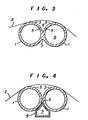
- Fig. 3 is a cross-sectional representation of a web handling device of this invention wherein bearing bars 1 are cylindrical.
- the bearing bars are joined at a weld 7 and the pressure chamber 4 is defined by the arcuate surfaces 3 of the bars from weld 7 through the shorter distance to the line of web proximity in operation.
- Fluid supply 5 is formed by holes in the wall of at least one of the bearing bars l; and fluid is delivered to fluid supply 5 by utilizing the interior of the bearing bars 1 as a plenum for the fluid.
- Fluid supply 5 can, also, be grooves or slots in the wall of at least one of the bearing bars 1 such that fluid is provided in nozzle-style as a continuum along the bar 1.
- Fig. 4 is a cross-sectional representation of a web handling device of this invention wherein bearing bars 1 are cylindrical and the surfaces are entirely holefree.
- Fluid supply 5 is by holes or a nozzle in plenum 8 shaped to fit closely to the contour of bearing bars 1 and used to direct fluid from plenum cavity 9 through fluid supply 5 into pressure chamber 4.
- Bearing bars 1 can be fixedly mounted or, because they are cylindrical and entirely holefree, can be rotatably mounted. In operation rotatably mounted bearing bars provide reduced relative motion, with moving webs; and such reduced relative motion reduces, even further, any effects of incidental contact between the web and the bearing bars 1.
Landscapes
- Engineering & Computer Science (AREA)
- Mechanical Engineering (AREA)
- Advancing Webs (AREA)
- Registering, Tensioning, Guiding Webs, And Rollers Therefor (AREA)
Applications Claiming Priority (2)
| Application Number | Priority Date | Filing Date | Title |
|---|---|---|---|
| US06/702,332 US4605146A (en) | 1985-02-15 | 1985-02-15 | Hydrostatic film support |
| US702332 | 1996-08-23 |
Publications (3)
| Publication Number | Publication Date |
|---|---|
| EP0192429A2 true EP0192429A2 (fr) | 1986-08-27 |
| EP0192429A3 EP0192429A3 (en) | 1987-10-07 |
| EP0192429B1 EP0192429B1 (fr) | 1991-05-29 |
Family
ID=24820783
Family Applications (1)
| Application Number | Title | Priority Date | Filing Date |
|---|---|---|---|
| EP86301018A Expired - Lifetime EP0192429B1 (fr) | 1985-02-15 | 1986-02-14 | Support hydrostatique de bande |
Country Status (5)
| Country | Link |
|---|---|
| US (1) | US4605146A (fr) |
| EP (1) | EP0192429B1 (fr) |
| JP (1) | JPH07121780B2 (fr) |
| CA (1) | CA1275664C (fr) |
| DE (1) | DE3679417D1 (fr) |
Cited By (2)
| Publication number | Priority date | Publication date | Assignee | Title |
|---|---|---|---|---|
| DE3626016A1 (de) * | 1986-07-31 | 1988-02-04 | Kurt Krieger | Vorrichtung zum beaufschlagen von materialbahnen mit stroemungsmedium |
| WO1988008950A1 (fr) * | 1987-05-09 | 1988-11-17 | Kurt Krieger | Dispositif pour le guidage flottant de bandes de materiau |
Families Citing this family (5)
| Publication number | Priority date | Publication date | Assignee | Title |
|---|---|---|---|---|
| DE4012176C2 (de) * | 1990-04-14 | 2000-08-17 | Pagendarm Technologie Gmbh | Vorrichtung zum Behandeln einer beschichteten Substratbahn |
| DE4334473C2 (de) * | 1993-10-11 | 1997-07-03 | Krieger Gmbh & Co Kg | Vorrichtung zum Schwebendführen einer laufenden Bahn |
| EP0705785A3 (fr) * | 1994-10-07 | 1996-11-13 | Eastman Kodak Co | Méthode et appareil pour éviter des plis dans des bandes fines |
| DE102005035750A1 (de) * | 2005-05-23 | 2006-11-30 | Windmöller & Hölscher Kg | Umlenkeinrichtung für eine Folienbahn |
| JP4901191B2 (ja) * | 2005-11-18 | 2012-03-21 | 東京応化工業株式会社 | レジスト希釈システム |
Family Cites Families (20)
| Publication number | Priority date | Publication date | Assignee | Title |
|---|---|---|---|---|
| DE975243C (de) * | 1951-04-03 | 1961-10-12 | Artos Maschb Dr Ing Meier Wind | Vorrichtung zum beruehrungsfreien Fuehren von zu trocknenden Bahnen |
| US3142870A (en) * | 1961-05-03 | 1964-08-04 | Whitin Machine Works | Selvage fiber control for combing machine |
| US3201935A (en) * | 1962-07-31 | 1965-08-24 | Monsanto Res Corp | Trialkylcyclohexane high energy fuels and propulsion process |
| US3319354A (en) * | 1964-11-13 | 1967-05-16 | Offen & Co Inc B | Air blowing nozzle |
| AT287479B (de) * | 1967-06-22 | 1971-01-25 | Jagenberg Werke Ag | Vorrichtung zum Ausgleich der Auswirkungen der Unrundheit von Wickelrollen |
| US3498515A (en) * | 1967-10-06 | 1970-03-03 | Michigan Oven Co | Fluid cushion turning rolls for supporting and guiding strip material |
| DE1951002C3 (de) * | 1969-10-09 | 1974-02-07 | Vits-Maschinenbau Gmbh, 4018 Langenfeld | Einrichtung zur berührungslosen Stabilisierung einer in ihrer Längsrichtung gespannten und bewegten Warenbahn |
| US3680223A (en) * | 1969-10-11 | 1972-08-01 | Vits Gmbh Maschbau | Apparatus for a non-contacting directional control of a web |
| US3763571A (en) * | 1970-04-27 | 1973-10-09 | Vits Maschinenbau Gmbh | Apparatus for contactless guiding of webs |
| FR2114934A5 (fr) * | 1970-12-04 | 1972-06-30 | Polytype Ag | |
| US3738018A (en) * | 1972-04-05 | 1973-06-12 | Agfa Gevaert Ag | Drying arrangement on machines for coating supporting webs, more especially with photographic emulsions |
| US3807057A (en) * | 1973-04-23 | 1974-04-30 | E Noel | Tray with disposable cup means for improved proofing and handling of doughballs for english muffins |
| US4043495A (en) * | 1975-03-03 | 1977-08-23 | Frank Sander | Air cushioned turn bar |
| JPS5425066A (en) * | 1977-07-28 | 1979-02-24 | Chugai Ro Kogyo Kaisha Ltd | Nonncontact type shape correcting and holding method of beltlike material and its device |
| US4197972A (en) * | 1978-08-28 | 1980-04-15 | W. R. Grace & Co. | Contactless turning guide having air slots longitudinally along running web edges |
| JPS55111344A (en) * | 1979-02-15 | 1980-08-27 | Akira Mitsuya | Sheet body supporting apparatus |
| JPS5628152A (en) * | 1979-08-08 | 1981-03-19 | Oji Paper Co Ltd | Air floating roll |
| GB2061230B (en) * | 1979-10-19 | 1983-03-30 | Loewy Robertson Eng Co Ltd | Web winding or unwinding apparatus with fluid supply means |
| US4472888A (en) * | 1982-06-04 | 1984-09-25 | Cary Metal Products, Inc. | Coanda effect nozzle for handling continuous webs |
| DE3225922C2 (de) * | 1982-07-10 | 1984-05-10 | M.A.N.- Roland Druckmaschinen AG, 6050 Offenbach | Luftumspülte Wendestange |
-
1985
- 1985-02-15 US US06/702,332 patent/US4605146A/en not_active Expired - Lifetime
-
1986
- 1986-02-13 JP JP61028071A patent/JPH07121780B2/ja not_active Expired - Lifetime
- 1986-02-13 CA CA000501808A patent/CA1275664C/fr not_active Expired - Lifetime
- 1986-02-14 EP EP86301018A patent/EP0192429B1/fr not_active Expired - Lifetime
- 1986-02-14 DE DE8686301018T patent/DE3679417D1/de not_active Expired - Lifetime
Cited By (4)
| Publication number | Priority date | Publication date | Assignee | Title |
|---|---|---|---|---|
| DE3626016A1 (de) * | 1986-07-31 | 1988-02-04 | Kurt Krieger | Vorrichtung zum beaufschlagen von materialbahnen mit stroemungsmedium |
| WO1988001038A1 (fr) * | 1986-07-31 | 1988-02-11 | Kurt Krieger | Dispositif d'application d'un milieu fluide sur des bandes de materiau |
| US4837947A (en) * | 1986-07-31 | 1989-06-13 | Kurt Krieger | Device for acting upon webs of material with a flowing medium |
| WO1988008950A1 (fr) * | 1987-05-09 | 1988-11-17 | Kurt Krieger | Dispositif pour le guidage flottant de bandes de materiau |
Also Published As
| Publication number | Publication date |
|---|---|
| JPS61188351A (ja) | 1986-08-22 |
| EP0192429B1 (fr) | 1991-05-29 |
| EP0192429A3 (en) | 1987-10-07 |
| JPH07121780B2 (ja) | 1995-12-25 |
| US4605146A (en) | 1986-08-12 |
| CA1275664C (fr) | 1990-10-30 |
| DE3679417D1 (de) | 1991-07-04 |
Similar Documents
| Publication | Publication Date | Title |
|---|---|---|
| US5979731A (en) | Method and apparatus for preventing creases in thin webs | |
| US5209387A (en) | Gas film conveyor for elongated strips of web material | |
| EP0784029B1 (fr) | Système de manipulation d'objets flexibles | |
| JP2001106402A (ja) | ウェブ搬送方法及び装置 | |
| JPH05124759A (ja) | ウエブ材料を案内し、偏向し、及び/又はそらすための差向け装置 | |
| US4434128A (en) | Method and apparatus for stretching thermoplastic polymer films | |
| US4605146A (en) | Hydrostatic film support | |
| EP0690017B1 (fr) | Appareil à faible inertie pour accumuler et appliquer une tension à des bandes | |
| US4790468A (en) | Floating type web guiding device | |
| DE1957485B2 (de) | Verfahren zur messung der bahnspannung | |
| US6152345A (en) | Method for controlling width-wise expansion of a conveyed web | |
| US5152080A (en) | Steerable air bar/edge dam apparatus | |
| US7081224B2 (en) | Polymer film producing method | |
| US3806018A (en) | Roll systems for webs of material | |
| EP0366481B1 (fr) | Appareil de revêtement de tissu | |
| JPH04213542A (ja) | ウエブの走行制御装置 | |
| US7159334B2 (en) | Web coating machine | |
| US4000803A (en) | Vacuum-buffered bidirectional paper drive system | |
| JP3012359B2 (ja) | ウエブを乾燥させる装置及びウエブ乾燥機 | |
| GB1584770A (en) | Guide device for flexible webs | |
| US4800656A (en) | Device and process for drying solvent-containing plastic sheets or films | |
| JP2735934B2 (ja) | 帯状材の進行方向変更装置 | |
| JP2597129B2 (ja) | ウエブ振動吸収装置 | |
| JP2599248Y2 (ja) | 帯状材の進行方向変更装置 | |
| JPH06144663A (ja) | 無接触搬送装置 |
Legal Events
| Date | Code | Title | Description |
|---|---|---|---|
| PUAI | Public reference made under article 153(3) epc to a published international application that has entered the european phase |
Free format text: ORIGINAL CODE: 0009012 |
|
| AK | Designated contracting states |
Kind code of ref document: A2 Designated state(s): BE DE FR GB IT LU NL |
|
| PUAL | Search report despatched |
Free format text: ORIGINAL CODE: 0009013 |
|
| AK | Designated contracting states |
Kind code of ref document: A3 Designated state(s): BE DE FR GB IT LU NL |
|
| 17P | Request for examination filed |
Effective date: 19880311 |
|
| 17Q | First examination report despatched |
Effective date: 19881219 |
|
| GRAA | (expected) grant |
Free format text: ORIGINAL CODE: 0009210 |
|
| AK | Designated contracting states |
Kind code of ref document: B1 Designated state(s): BE DE FR GB IT LU NL |
|
| ITF | It: translation for a ep patent filed | ||
| ET | Fr: translation filed | ||
| REF | Corresponds to: |
Ref document number: 3679417 Country of ref document: DE Date of ref document: 19910704 |
|
| PGFP | Annual fee paid to national office [announced via postgrant information from national office to epo] |
Ref country code: BE Payment date: 19920312 Year of fee payment: 7 |
|
| PLBE | No opposition filed within time limit |
Free format text: ORIGINAL CODE: 0009261 |
|
| STAA | Information on the status of an ep patent application or granted ep patent |
Free format text: STATUS: NO OPPOSITION FILED WITHIN TIME LIMIT |
|
| 26N | No opposition filed | ||
| PG25 | Lapsed in a contracting state [announced via postgrant information from national office to epo] |
Ref country code: BE Effective date: 19930228 |
|
| BERE | Be: lapsed |
Owner name: E.I. DU PONT DE NEMOURS AND CY Effective date: 19930228 |
|
| EPTA | Lu: last paid annual fee | ||
| NLS | Nl: assignments of ep-patents |
Owner name: DUPONT TEIJIN FILMS U.S. LIMITED PARTNERSHIP |
|
| REG | Reference to a national code |
Ref country code: FR Ref legal event code: TP |
|
| REG | Reference to a national code |
Ref country code: GB Ref legal event code: IF02 |
|
| REG | Reference to a national code |
Ref country code: GB Ref legal event code: 732E |
|
| PGFP | Annual fee paid to national office [announced via postgrant information from national office to epo] |
Ref country code: NL Payment date: 20050203 Year of fee payment: 20 |
|
| PGFP | Annual fee paid to national office [announced via postgrant information from national office to epo] |
Ref country code: FR Payment date: 20050208 Year of fee payment: 20 |
|
| PGFP | Annual fee paid to national office [announced via postgrant information from national office to epo] |
Ref country code: GB Payment date: 20050209 Year of fee payment: 20 |
|
| PGFP | Annual fee paid to national office [announced via postgrant information from national office to epo] |
Ref country code: DE Payment date: 20050210 Year of fee payment: 20 |
|
| PGFP | Annual fee paid to national office [announced via postgrant information from national office to epo] |
Ref country code: LU Payment date: 20050216 Year of fee payment: 20 |
|
| PGFP | Annual fee paid to national office [announced via postgrant information from national office to epo] |
Ref country code: IT Payment date: 20050225 Year of fee payment: 20 |
|
| PG25 | Lapsed in a contracting state [announced via postgrant information from national office to epo] |
Ref country code: GB Free format text: LAPSE BECAUSE OF EXPIRATION OF PROTECTION Effective date: 20060213 |
|
| PG25 | Lapsed in a contracting state [announced via postgrant information from national office to epo] |
Ref country code: NL Free format text: LAPSE BECAUSE OF EXPIRATION OF PROTECTION Effective date: 20060214 |
|
| REG | Reference to a national code |
Ref country code: GB Ref legal event code: PE20 |
|
| NLV7 | Nl: ceased due to reaching the maximum lifetime of a patent |
Effective date: 20060214 |