EP0193151A2 - Verfahren zur Bildanzeige - Google Patents
Verfahren zur Bildanzeige Download PDFInfo
- Publication number
- EP0193151A2 EP0193151A2 EP86102358A EP86102358A EP0193151A2 EP 0193151 A2 EP0193151 A2 EP 0193151A2 EP 86102358 A EP86102358 A EP 86102358A EP 86102358 A EP86102358 A EP 86102358A EP 0193151 A2 EP0193151 A2 EP 0193151A2
- Authority
- EP
- European Patent Office
- Prior art keywords
- data
- triangular
- apexes
- visible
- point
- Prior art date
- Legal status (The legal status is an assumption and is not a legal conclusion. Google has not performed a legal analysis and makes no representation as to the accuracy of the status listed.)
- Granted
Links
Images


Classifications
-
- G—PHYSICS
- G06—COMPUTING OR CALCULATING; COUNTING
- G06T—IMAGE DATA PROCESSING OR GENERATION, IN GENERAL
- G06T15/00—Three-dimensional [3D] image rendering
- G06T15/50—Lighting effects
-
- G—PHYSICS
- G06—COMPUTING OR CALCULATING; COUNTING
- G06T—IMAGE DATA PROCESSING OR GENERATION, IN GENERAL
- G06T15/00—Three-dimensional [3D] image rendering
- G06T15/005—General purpose rendering architectures
Definitions
- the present invention relates generally to a method of displaying an image and more specifically to a computerized method of displaying on a two-dimensional, raster scan display screen an image lying within a three-dimensional space.
- the feeling of distance can be displayed by changing the size of an object in proportion to the distance to an observing point on the basis of the fact that the near is perceived as large and the far is perceived as small whenever an object is seen through human eyes.
- the ups-and-downs of surfaces of an object are displayed by changing the apparent brightness of the illumination on each surface of a graphic image represented on a display screen on the basis of the fact that the inclinations of the outer surfaces of an object are different from each other relative to a light source positioned at a point within a three-dimensional space so that the human eye sees the object as if the brightness on each surface of an object changes.
- the feeling of distance can be represented by not displaying the graphic image of nonvisible portions. This derives from the fact that when objects are seen from an observing point within a three-dimensional space, one cannot see the rear surfaces of an object or the surfaces of backward positioned objects upon which frontward positioned objects are superposed.
- the spatial positional relationship between a light source and an object is set so as to be initialized; the perspective transformation processing, the shadow processing and the hidden surface processing are executed by subroutine.
- the above three processings for solid representation can be executed in sequence, respectively.
- the method according to the present invention comprises the following computational steps of: (a) dividing a surface of the object into a plurality of triangular unit areas to obtain first sets of plural data representative of object surface image information at the three apexes of each triangular unit area; (b) perspectively transforming only the positional data representative of the positions of the three apexes of each triangul-ar unit area, which data is included in the first plural data, onto a two-dimensional plane corresponding to the display screen, in relation to the predetermined observing point to obtain second positional data representative of the positions of second sets of three apexes, corresponding to the three apexes of each triangular unit area as transformed onto the two-dimensional plane; (c) vertically setting other object surface image information data included in the first data separately at the second three apexes of each triangular unit area on the two-dimensional plane to separately form plural triangular image data planes at three tops of the vertically set object surface image information data
- the method according to the present invention comprises the steps of determining a display area on the display screen within which an object image is to be displayed on the two-dimensional plane by selecting the maximum and minimum values of the second positional data representative of positions of the second three apexes on the two-dimensional plane, calculating a center of the displayed object image, and executing the display processing of the object surface information data only for points representing pixels which are included within the determined display area.
- this method of excluding calculations for pixels outside of the display area comprises the following steps of: (a) calculating each center of gravity of each triangular unit area on the two-dimensional plane and (b) determining a triangular unit area within which the current processed point representing a display pixel lies on the basis of each calculated center of gravity and the three sides of the triangular unit area before computationally, vertically setting the object surface image information data, included in the first data, at the second three apexes of the triangular unit area on the two-dimensional plane.
- the object surface image information are luminance data, visible-nonvisible data, and distance data at the three apexes of each triangular unit area for providing shadow surfaces and hidden surfaces on the displayed object image.
- a surface of an object corresponding to one patch is separated into plural triangular unit areas; (2) image information data (luminance, visible-nonvisible, and distance data) are formed at each apex; (3) only the three apex positional data are perspectively transformed to the two-dimensional plane; (4) a display area is previously determined; (5) a triangular unit area including pixels to be processed is determined; and (6) image information data are calculated only at each pixel included within the display area in accordance with interpolation, whereby it is possible to markedly reduce the processing time required by the data processing computer.
- the shadow processing and the hidden surface processing necessary for displaying a solid graphic image on a two-dimensional raster screen are executed in accordance with the method as described below.
- the shadow processing is to allow the depiction of shadows on the surfaces of a graphic image displayed on a display screen.
- the luminance i.e., brightness
- the shadow processing is expressed by where I is the luminance at the position P1 by which a shadow produced by the light source 2 on the surface of the object 1 can be represented; D is a constant; and A is a variable expressed as
- variable A can be expressed by a formula such that the inner product of light source vector K * and normal unit vector N * at position P1 is divided by the product of the absolute values of the light source vector K * and the normal unit vector N * .
- This formula indicates the cosine of an angle 6 subtended by the light source vector K * and the normal unit vector N * .
- the position of the light source 2 is expressed by a position vector SS * on absolute coordinates x, y, z, and the position P 1 of the curved surface 1A is expressed by a curved surface position vector S*.
- the gradient of the curved surface 1A at this position P1 is expressed by the normal unit vector N * on the curved surface 1A.
- the direction of light incident from the light source 2 upon the position P1 is expressed by a vector K * drawn from the position P1 to the light source 2.
- the incident angle of the light is expressed by an angle ⁇ subtended by the normal unit vector N * and the light source vector K * .
- the luminance I at the position P1 on the curved surface 1A is determined by the variable A. Therefore, if the incident angle ⁇ of the light allowed to be incident from the light source 2 upon the position P1- varies, the variable A varies within the range between -1 and +1 according to the change in the angle e. If the incident angle ⁇ is 0° (i.e. the light source is in the direction of the normal unit vector N * at the position P1 on the curved surface 1A) the luminance at the position P1 is the brightest. If the incident angle 9 changes between +90°, the luminance at the position P1 decreases (i.e. the luminance I goes down to zero).
- each portion on the curved surface 4A is visible or not is made on the basis of the following two conditions:
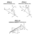
- the first condition as depicted in Fig. 2, when the curved surface 4A of object 4 is seen from the observing point 3 along the line of sight EL1, there are points of intersections P11, P12 and P13 of the sight line EL1 and the curved surface 4A. It is to be understood that these points are only representative of all points on the surface.
- the surface portion between the positions P12 and P13 is hidden because there exists a surface which intersects the sight line EL1 at the position P11 on the side of the observing point 3.
- the surface portion between positions P12 and P13 is determined to be non-visible, and graphic image data transformation processing is executed in such a way that the visible surface portion at the position P11 is seen on a phantom screen 5 d.isposed between the object 4 and the observing point 3.
- This "phantom screen” is a computational artifice representing the position of the two-dimensional display screen relative to the three-dimensional object.
- the second condition is that the surface portions to be displayed are not hidden by other objects, i.e., surfaces other than surface 4A.
- the sight line EL2 intersects the curved surface 6A of the object 6 before intersecting the curved surface 4A.of the object 4. That is, the surface portion at the position P14 on the object curved surface 4A is hidden by the surface portion at the position P15 on the object curved surface 6A. Therefore, graphic image data transformation processing is executed in such a way that the non-visible surface portion at the position P14 is not displayed but the visible surface portion at the position P 15 is displayed on a phantom screen 5.
- the first condition (i.e., visible or non-visible) can be determined in accordance with the method shown in Fig. 3.
- a sight line unit vector E * pointing to the observing point 3 is drawn at a point P21 on an object 7 (i.e., a sphere) having an enclosed curved surface 7A in order to obtain an inner product of this sight line unit vector E * and the normal unit vector N * , the necessary and sufficient condition that the surface portion at point P21 is visible can be expressed as
- the above determination is to judge whether the gradient of the surface portion at each point lying on the curved surface 7A faces to the observing point 3 or not. Such points are referred to as visible candidate points.
- the visible candidate points are finally determined to be visible points only when the above second condition is satisfied. That is, as explained with reference to Fig. 2, a visible candidate point P11 or P15 having the nearest distance to the observing point 3 is selected from a plurality of visible candidate points (P11, P12, Pt3).or (P14, P15) lying on the line of sight EL1 or EL2, and the selected point is determined to be a final visible point, respectively.
- An image display system which adopts a computer graphic method executes the graphic image transformation processing of the present invention by means of a central processing unit (CPU) (not shown) and in accordance with the processing procedure shown in Fig. 4.
- CPU central processing unit
- step SP1' the transformation processing control program starts.
- step SP2 the data describing the positions of observing point 3 (Fig. 4) and light source (Fig. 1) and the number of patches necessary for transformation processing a graphic image are inputted by an operator to the CPU.
- the CPU forms a perspective transformation matrix used for transforming points on curved surfaces of a three-dimensional graphic image onto the corresponding points on a view plane 5 in step SP3. That is, the above matrix is necessary when a three-dimensional graphic image represented by the graphic image data is perspectively displayed on the view plane 5 (Fig. 2) determined on the basis of the observing point 3 preset at step SP2.
- the CPU reads data DATA for one patch of graphic image data to be transformed and displayed in step SP4, and divides the DATA, as if the patch were cut into triangular shapes, in step SP5.
- the dividing of the data into triangles is as follows: the data DATA for one patch are read by the CPU from its memory in sequence, and the intersections of two groups of computed cutting lines L1 and L2 are calculated in sequence on the basis of predetermined parameters.
- the two groups of the cutting lines are arranged at regular intervals, although not necessarily spaced at regular intervals on the curved surface.
- the number of lines of the cutting line group L1 and L2 is selected as five in the horizontal and vertical directions in such a way that the two cutting line groups L1 and L2 intersect each other in a net-like arrangement.
- a curved surface composed of one-patch data DATA is divided into small areas UA surrounded by two pairs of.adjacent lines of the cutting line groups L1 and L2 and each small area UA is cut off for processing so as to be surrounded by four intersection points PX.
- the size of this small area UA is determined in association with the number of patches inputted at step SP2.
- the small area UA is transformed on a display raster screen, the number of pixels included within the transformed small area can be automatically determined.
- the small areas UA are each further divided into two triangular unit areas UA1 and UA2 respectively by diagonal lines L3 connecting two points of intersection PX diagonally opposite to each other, so that a curved surface represented by data DATA is divided into a number of triangular unit areas UA1 and UA2.
- the number of pixels included in each triangular unit area UA1 or UA2 is 20 to 30, for instance.
- the CPU calculates a normal unit vector N * at three intersection points, that is, at the apexes of each triangular unit area UA1 or UA2.
- the CPU computes a table in memory, including visible and nonvisible data used for hidden surface processing.
- the CPU calculates siqht line unit vectors E * at the three apexes of the triangular unit areas UA1 and UA2, respectively, as shown in Fig. 7; calculates each inner product of the sight line unit vector E * and the normal unit vector N * ; and sequentially stores these calculated results in the visible-nonvisible table TABLE 4 of a table 10 provided within the memory of the computer, as shown in Fig. 5.
- the curved surface data DATA (Fig. 6) for one patch are stored as data of 25 words per patch being divided into five intersections, respectively in the direction that the cutting line group L2 is arranged (referred to as U direction) and the direction that the cutting line group L1 is arranged (referred to as V direction).
- the visible-nonvisible data for 25 intersections PX are stored for each patch in order to form the first condition data necessary for hidden surface processing as described with reference to Fig. 2.
- the CPU forms a distance table.
- the distance table is formed by the CPU by calculating a distance vector D * from the apex PX to the observing point 3 at each apex of the curved surface data DATA as shown in Fig. 8 and by storing the calculated results in a distance table TABLE 3 of the table 10.
- the distance data D in this distance table TABLE 3 are used for determining the second condition (Fig. 2) in hidden surface processing.
- the distance vector from the apex PX to the observing point 3 can be calculated as
- the distance data D is obtained by calculating the absolute value of the distance vector D * .
- the CPU calculates the data of the curved surface portion nearest to the observing point 3 to be the distance data and to exclude distance data for the same pixel which is further away, i.e., for a surface point which is hidden to the observing point 3.
- step SP8 the CPU calculates a luminance table for storage in memory.
- the luminance at each apex is calculated as follows: The positional vector K * from the apex PX to the light source 2 is calculated. Then, the cosine of the incident angle 6 is calculated on the basis of the inner product of the calculated result K * and the normal unit vector N * at apex PX as
- the calculated result is represented by a variable A.
- the luminance I can be calculated by the use of the variable A as follows:
- the luminance I primarily changes according to the change in the light allowed to be incident from the light source 2 upon the apex PX.
- the CPU proceeds to step SP9 for executing the perspective transformation processing.
- the perspective transformation processing is to transform the apexes PX on the curved surface 4A within a three-dimensional space onto a two-dimensional X-Y plane of a view plane 5, which represents the raster scan display screen, when the positions of the apexes PX on the curved surface 4A of an object 4 are perspectively seen on the view plane 5 disposed between the object 4 and the observing point 3.
- the transformation processing can be executed by transform-calculating the positional data at apexes PX obtained in the above step SP5 onto the X-Y plane on the basis of the perspective transformation matrix formed in the step SP3.
- the calculated results are stored in the XY table TABLE 1 of the table 10.
- the CPU determines whether the processing has been completed for the data for all the patches set as initial values in step SP2. If not completed, the CPU returns to the step SP4 to compute the succeeding patch data in the table 10. If YES is obtained in the step SP10, the CPU can store in its memory all the information representative of the curved surface states to be displayed on the display screen in the table 10 in relation to three apex positional data of the triangular unit areas UA1 and UA2 (Fig. 6), respectively.
- each triangular unit area UA1 or UA2 corresponds to 20 to 30 pixels on the display screen
- linear interpolation calculation is executed for each pixel by the use of the data in table 10 in order to obtain image data for the shadow processing and the hidden surface processing.
- image data On the basis of these image data, it is possible to solidly reproduce a plane image on the display screen.
- the CPU executes the processing for determining a display areal
- This processing step is to determine a display area so that an image can be displayed at roughly the central position of a display screen in an appropriate dimension.
- all the data are read from memory from the XY table TABLE I (Fig. 5) of the table 10 in order to extract the maximum value Xmax and the minimum value Xmin in the X-axis direction and the maximum value Ymax and the minimum value Ymin in the Y-axis direction of the perspectively-transformed apex positional data which configure a two-dimensional display image DES.
- the middle position Xc between the maximum value Xmax and the minimum value Xmin in the X direction is obtained by the following formula:
- the middle position Yc between the maximum value Ymax and the minimum value Ymin in the Y direction is determined by the following formula:
- the central position (Xc, Yc) can be obtained and is set to a central position on the display raster screen 11.
- the display area ARE is determined so that the-displayed image DES can be accommodated within the capacity of a frame buffer memory having memory cells corresponding to pixels which configure the display screen 11.
- the display area has an area extending from the maximum value Xmax to the minimum value Xmin in the X direction and from the maximum value Ymax to the minimum value Ymin in the Y direction as depicted in Fig. 11.
- the CPU executes all succeeding processing steps only for pixels lying within the display area ARE.
- This feature markedly reduces the amount of transformation calculation for an image to be displayed on the raster screen.
- a transformation-processed image is displayed on a raster screen
- the method illustrated in Fig. 11 since no calculation processing is made for pixels having no data to be displayed, it is possible to considerably reduce the amount of image transformation calculations as a whole.
- the CPU reads the positional data DATAX (Fig. 12) for one patch, corresponding to the apexes of the triangular unit areas UA1 and UA2 in this display area ARE, in sequence from the XY table TABLE 1 of the table 10 in order to execute interpolation calculation processing. That is, the CPU supplies data necessary for interpolation calculations in order to determine the luminance of pixels included within the triangular areas UA1X and UA2X lying within the display area ARE on the display screen (Figs. 11 and 12).
- the CPU determines whether the current pixel (referred to as a processed point) Pc belongs to the triangular area UA1X or UA2X, that is whether the processed point Pc (Xc, Yx) lies within the triangular area UAX or not.
- the procedure for accomplishing this uses the center of gravity Po (Xo, Yo) of the triangular area UAX surrounded by three straight lines DL1, DL2 and DL3 connecting between the apexes P1 (X1, Y1), P2 (X2, Y2) and P3 (X3, Y3) mutually on the X-Y plane obtained by the perspectively-transformed .
- three apexes of each triangular area UA1X or UA2X which were calculated in step SP9 (Figs. 4 and 10), stored in TABLE 1, as depicted in Fig. 13.
- F(X,Y) is zero. However, if coordinate values of points inside or outside the straight line DL1 are substituted, F(X,Y) is a positive or negative value.
- the processed point Pc(Xc,Yc) lies on the side of gravity center Po(Xo,Yo) away from all the straight lines DL1, DL2 and DL3 constituting three sides of the triangular area UAX. Since it is evident that the center of gravity of a triangle lies inside the three sides thereof, it is therefore possible to determine that the processed point Pc(Xc,Yc) lies within the triangular area UAX.
- the processed point Pc(Xc,Yc) must lie on the side opposite to the gravity center Po(Xo,Yo) away from one or more straight lines DL1, DL2 and DL3, thus the processed point Pc is thereby determined by the CPU to not lie within the triangular area UAX.
- the CPU does not execute the succeeding interpolation calculations for that point, i.e., that pixel, in processing the points for that triangular area. The same determination will be repeated for new triangular areas UAX until a triangular area UAX including a processed point Pc inside is found out.
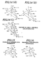
- the CPU proceeds to the succeeding step SP14 to execute the processing of visible-nonvisible determination on the basis of linear interpolation. That is, the CPU reads in sequence the visible-nonvisible data stored for each triangular apex P1, P2, P3 from the visible-nonvisible table TABLE 4 (Fig. 5) of the table 10 in order to computationally, vertically set the corresponding visible-nonvisible data vectors VI 1 , VI 2 , VI 3 at the positions P1, P2, P3 on the display screen as depicted in Fig.
- This visible-nonvisible plane VPX changes in dependence upon the values of the visible-nonvisible data VI 1 , VI 2' VI 3 set at the apexes P1, P2, P3 as follows: If all the visible-nonvisible data VI 1 to V I 3 are "+1" in value, it is possible to obtain a visible-nonvisible plane VPX extending in parallel to and above the triangular area UAX as depicted in Fig. 14(A). In contrast with this, if. all the visible-nonvisible data VI 1 to VI 3 are "-1" in value, it is possible to obtain a visible-nonvisible plane VPX extending in parallel to and below the triangular area UAX as depicted in Fig. 14(B).
- any one or two parts (e.g. VI 1 and VI2 ) of the visible-nonvisible data VI 1 to VI 3 are "+1" and the remaining part (e.g. VI 3 ) is "-1"
- the visible-nonvisible plane VPX intersects the triangular area UAX, as depicted in Fig. 14(C), in such a way that the visible-nonvisible plane VPX existing on the sides of apexes P1 and P2 away from the intersectional line LIN is positive and the plane VPX existing on the side of apex P3 away from the line LIN is negative.
- the point VI pc of the intersection of the straight line LC1 passing through the processed point Pc and perpendicular to the triangular area UAX (e.g. the display raster screen) and the visible-nonvisible plane VPX is determined and the value VI pc is interpolated as the visible-nonvisible data at the processed point Pc.
- the values of VI pc in Figs. 14(A) and 14(C) are positive and thus the data at the points Pc are classified as visible data.
- the values of VI pc in Fig. 14(B) and VI pc in Fig. 14(C) are negative, indicating nonvisible data is at the points Pc (Fig. 14(B)) and Pc' (Fig. 14(C)), respectively.
- the CPU proceeds to the step SP15 to execute the luminance determination processing in accordance with linear interpolation.
- the luminance Ipc at the processed point Pc of a pixel included within the triangular area UAX is interpolation-calculated on the basis of the luminance data I1, 12, 13 at the apexes P1, P2, P3 of the triangular area UAX on the display screen following a procedure similar to that used for determining visible-nonvisible data.
- the luminance data I1, I2, I3 at the apexes P1, P2, P3 of the triangular area UAX are read from the luminance table TABLE 2 of the table 10 and are computationally set vertically at the corresponding apexes P1, P2, P3 on the display screen.
- a luminance plane BPX is calculated which intersects each top end of the luminance data vectors I1, 12, 13.
- a straight line LC2 is set perpendicular to the display screen at the processed point Pc of each pixel included within the triangular area UAX.: The point of intersection of the straight line LC2 and the luminance plane BPX is obtained. The value at the intersection on the luminance plane BPX is determined to be the luminance Ipc at the processed point Pc.
- the CPU executes the distance determination processing in accordance with interpolation calculation.
- the distance from the observing point is interpolation-calculated by the CPU for each pixel included within the triangular area UAX on the display screen following a procedure similar to those just previously described.
- the distance data D1, D2, D3 at the apexes P1, P2, P3 on the display screen are read from the distance table TABLE 3 of the table 10 and are computationally set vertically at the apexes P1, P2, P3.
- a distance plane DPX is calculated by the CPU to intersect each top end of the distance data vectors D1, D2, D3.
- the intersection between the straight line LC3 passing through the processed point Pc and perpendicular to the display screen and the distance plane DPX is calculated by the CPU.
- the value at this intersection on the distance plane DPX is determined to be the distance Dpc at the processed point Pc from the observing point.
- the CPU proceeds to the step SP17 to execute the processing of forming the pixel data on the basis of distance comparison.
- the luminance data Ipc (Fig. 15) and the visible-nonvisible data VIpc (Fig. 14) corresponding to a curved surface with the smallest distance data Dpc are collected for all the pixels included within the display area ARE (Fig. 11) on the display screen.
- the luminance data of the curved surface having the visible data and the smallest distance data Dpc are assembled in the CPU as pixel data to be displayed on the display screen.
- the CP U includes a frame buffer memory having a plurality of memory cells, each corresponding to a display pixel, and a depth buffer memory corresponding to each pixel of the frame buffer memory.
- the distance data D pc corresponding to each pixel is determined and the smallest distance data Dpc for the same pixel is obtained, the distance data are stored in the memory areas corresponding to the pixels of the depth buffer memory and simultaneously the luminance data Ipc determined in the step SP15 are stored in the frame buffer memory. Therefore, the luminance data Ipc obtained from the curved surface having the smallest distance data Dpc are to be written in the frame buffer memory.
- step SP17 The above-mentioned serial calculation processings from SP12 to SP17 are executed for each pixel included within one patch. Whenever the processing of step SP17 has been completed, the CPU determines whether the calculation processing has been completed for all the patches in the step SP17. If the result is NO, the CPU returns to the step SP12 again to repeat the calculation processing of data for new pixels. In contrast with this, if the result is YES in the step SP18, the CPU proceeds to the step SP19 to complete the program control.
- a CPU is programmed to perspectively transform the curved surfaces of an object lying within a three-dimensional space when seen from a predetermined observing point on a_two-dimensional display screen for displaying an image.
- the curved surfaces of the object within a three-dimensional space are computationally divided into a plurality of triangular unit areas UA1 and UA2 in order to obtain the object surface information data represented at three apexes PX.
- a triangular data plane composed of object surface information data on the curved surface is formed at the apexes P1, P2, P 3 transformed on. the two-dimensional plane, so that it is possible to obtain image data for all the pixels included within the triangular area on the screen using linear interpolation calculations.
- the image data for each pixel is obtained by calculating, using linear interpolation, a solution of the intersection between the data plane and a straight line passing through the point in the two dimensional plane which point corresponds to the pixel on the display screen. The solution can thus be calculated by the CPU simply and definitely.
- the luminance data plane can be formed by the CPU on the basis of the triangular unit area UAX on the two-dimensional plane, it is possible to easily provide shadow according to the position of a light source on the image displayed on the screen so as to stably reproduce the ups and downs on the curved surfaces of an object.
- the CPU since it is possible for the CPU to clearly determine the boundary between visible area and nonvisible area on the basis of the results of the linear interpolation calculation for each pixel by providing the visible-nonvisible data plane on the two-dimensional plane, even in the case where the visible area and the nonvisible area are both present within the triangular area UAX on the two-dimensional plane, the CPU can readily execute the hidden surface processing.
- the CPU can securely execute the hidden surface processing without confusion and thus produce an image having a clear feeling of distance on the display screen.
- a triangular area UAX to which the processed point Pc (corresponding to the currently processed pixel) belongs is determined by the CPU by simply calculating whether the processed point Pc lies on the side of the gravity center Po using the three straight lines DL 1, DL 2, DL3 to define the three sides of the triangular area UAX and calculating the gravity center Po of the triangular area UAX, as explained in greater detail above.
- This allows a marked reduction in calculation processing time compared to prior art methods which simply processed the data for all pixels.
- the positional data of an object lying within a three-dimensional space and seen from a specified observing point are perspectively transformed onto a two-dimensional plane; a display area ARE (Fig. 11) in which the transformed positional data lie is determined; and the above described series of image display processing calculations (that is, determination of a triangular area within which the processed point lies, determination of visible-nonvisible area, determination of the distance from the observing point, determination of the visible surfaces) are executed only for this display area ARE. This also greatly reduces the time required for the calculations compared to prior art methods.
- the maximum and the minimum values are determined in both the X and Y directions.
- the curved surface of an object lying within a three-dimensional space is divided by the CPU into triangular unit areas UA1 and UA2 for computational purposes and the image information of the unit area UA1 or UA2 is represented by three apexes PX of each unit area UA1 or UA2, it is possible to execute the image transformation processing in accordance with simple calculations and to markedly reduce the image transformation processing time.
- the CPU when the image information to be displayed on the display screen is obtained, the CPU first determines the display area representative of an area within which an object is to be substantially displayed and then executes the data transformation and display processing for only the pixels included within the determined display area. Thus no data transformation and display processing is executed by the CPU for pixels included in other areas within which an object is not displayed, thereby making it possible to reduce the calculation time as a whole.
Landscapes
- Engineering & Computer Science (AREA)
- Computer Graphics (AREA)
- Physics & Mathematics (AREA)
- General Physics & Mathematics (AREA)
- Theoretical Computer Science (AREA)
- Image Generation (AREA)
Priority Applications (1)
| Application Number | Priority Date | Filing Date | Title |
|---|---|---|---|
| AT86102358T ATE97246T1 (de) | 1985-02-26 | 1986-02-24 | Verfahren zur bildanzeige. |
Applications Claiming Priority (6)
| Application Number | Priority Date | Filing Date | Title |
|---|---|---|---|
| JP3707785A JPS61195467A (ja) | 1985-02-26 | 1985-02-26 | 画像表示方法 |
| JP37078/85 | 1985-02-26 | ||
| JP3707885A JPS61195468A (ja) | 1985-02-26 | 1985-02-26 | 画像表示方法 |
| JP37077/85 | 1985-02-26 | ||
| JP37079/85 | 1985-02-26 | ||
| JP3707985A JPH0814852B2 (ja) | 1985-02-26 | 1985-02-26 | 画像表示方法 |
Publications (3)
| Publication Number | Publication Date |
|---|---|
| EP0193151A2 true EP0193151A2 (de) | 1986-09-03 |
| EP0193151A3 EP0193151A3 (en) | 1989-11-29 |
| EP0193151B1 EP0193151B1 (de) | 1993-11-10 |
Family
ID=27289317
Family Applications (1)
| Application Number | Title | Priority Date | Filing Date |
|---|---|---|---|
| EP86102358A Expired - Lifetime EP0193151B1 (de) | 1985-02-26 | 1986-02-24 | Verfahren zur Bildanzeige |
Country Status (4)
| Country | Link |
|---|---|
| US (1) | US4819192A (de) |
| EP (1) | EP0193151B1 (de) |
| CA (1) | CA1260638A (de) |
| DE (1) | DE3689271T2 (de) |
Cited By (5)
| Publication number | Priority date | Publication date | Assignee | Title |
|---|---|---|---|---|
| EP0314341A3 (de) * | 1987-10-30 | 1991-07-24 | International Business Machines Corporation | Rechnergraphikgerät zur Verarbeitung von Beleuchtungsmodellinformation |
| GB2243523A (en) * | 1990-04-24 | 1991-10-30 | Rediffusion Simulation Ltd | Generating elliptical objects |
| WO1993001561A1 (en) * | 1991-07-12 | 1993-01-21 | Hong Lip Lim | A beam tracing method for curved surfaces |
| FR2693012A1 (fr) * | 1992-06-26 | 1993-12-31 | Thomson Csf | Procédé de visualisation d'images synthétiques de volumes en temps réel. |
| US5914721A (en) * | 1991-06-28 | 1999-06-22 | Lim; Hong Lip | Visibility calculations for 3D computer graphics |
Families Citing this family (40)
| Publication number | Priority date | Publication date | Assignee | Title |
|---|---|---|---|---|
| US4928233A (en) * | 1987-08-24 | 1990-05-22 | International Business Machines | System for providing three dimensional object descriptions |
| US4912659A (en) * | 1987-10-30 | 1990-03-27 | International Business Machines Corporation | Parallel surface processing system for graphics display |
| US4930091A (en) * | 1987-11-04 | 1990-05-29 | Schlumberger Systems, Inc. | Triangle classification setup method and apparatus for 3-D graphics display system |
| US5083287A (en) * | 1988-07-14 | 1992-01-21 | Daikin Industries, Inc. | Method and apparatus for applying a shadowing operation to figures to be drawn for displaying on crt-display |
| US4985854A (en) * | 1989-05-15 | 1991-01-15 | Honeywell Inc. | Method for rapid generation of photo-realistic imagery |
| US5060172A (en) * | 1989-07-06 | 1991-10-22 | Digital Equipment Corporation | Method and apparatus for displaying smooth-shaded objects |
| JPH0776991B2 (ja) * | 1989-10-24 | 1995-08-16 | インターナショナル・ビジネス・マシーンズ・コーポレーション | Nurbsデータ変換方法及び装置 |
| JP3019398B2 (ja) * | 1990-01-21 | 2000-03-13 | ソニー株式会社 | 自由曲面加工データ作成方法 |
| EP0464214A4 (en) * | 1990-01-21 | 1993-04-14 | Sony Corporation | Free surface data preparation method |
| US5388202A (en) * | 1990-02-02 | 1995-02-07 | Viacom International Inc. | Method and apparatus for generating window borders having pictorial frame elements |
| AU7313491A (en) * | 1990-02-16 | 1991-09-03 | Silicon Graphics, Inc. | Method and apparatus for providing a visually improved image by converting a three-dimensional quadrilateral to a pair of triangles in a computer system |
| US5222204A (en) * | 1990-03-14 | 1993-06-22 | Hewlett-Packard Company | Pixel interpolation in perspective space |
| US5163126A (en) * | 1990-05-10 | 1992-11-10 | International Business Machines Corporation | Method for adaptively providing near phong grade shading for patterns in a graphics display system |
| US5313560A (en) * | 1990-05-11 | 1994-05-17 | Hitachi, Ltd. | Method for determining a supplemental transaction changing a decided transaction to satisfy a target |
| US5289383A (en) * | 1990-05-17 | 1994-02-22 | Sony Corporation | Method for establishing data defining tool path for rough machining |
| US5268996A (en) * | 1990-12-20 | 1993-12-07 | General Electric Company | Computer image generation method for determination of total pixel illumination due to plural light sources |
| US5455902A (en) * | 1990-12-21 | 1995-10-03 | Eastman Kodak Company | Method and apparatus for performing real-time computer animation |
| US5343558A (en) * | 1991-02-19 | 1994-08-30 | Silicon Graphics, Inc. | Method for scan converting shaded triangular polygons |
| JP3028116B2 (ja) * | 1991-02-28 | 2000-04-04 | ソニー株式会社 | 形状データ処理方法及び形状データ処理装置 |
| US5706415A (en) * | 1991-12-20 | 1998-01-06 | Apple Computer, Inc. | Method and apparatus for distributed interpolation of pixel shading parameter values |
| US5345541A (en) * | 1991-12-20 | 1994-09-06 | Apple Computer, Inc. | Method and apparatus for approximating a value between two endpoint values in a three-dimensional image rendering device |
| US5566292A (en) * | 1992-04-17 | 1996-10-15 | International Business Machines Corporation | Methods for detecting the closest existing point on a spline or polyline |
| GB2270243B (en) * | 1992-08-26 | 1996-02-28 | Namco Ltd | Image synthesizing system |
| US5684937A (en) * | 1992-12-14 | 1997-11-04 | Oxaal; Ford | Method and apparatus for performing perspective transformation on visible stimuli |
| GB9303009D0 (en) * | 1993-02-15 | 1993-03-31 | Canon Res Ct Europe Ltd | Processing image data |
| WO1994023390A1 (en) * | 1993-03-29 | 1994-10-13 | Matsushita Electric Industrial Co., Ltd. | Apparatus for identifying person |
| US5495562A (en) * | 1993-04-12 | 1996-02-27 | Hughes Missile Systems Company | Electro-optical target and background simulation |
| KR19980701470A (ko) * | 1995-11-14 | 1998-05-15 | 이데이 노부유키 | 특수 효과 장치, 화상 처리 방법, 및 새도우 생성 방법 |
| JP3926866B2 (ja) | 1996-05-10 | 2007-06-06 | 株式会社ソニー・コンピュータエンタテインメント | 情報処理装置、情報処理方法、及び描画システム |
| DE69826996T2 (de) * | 1997-05-07 | 2005-03-10 | Sega Corp. | Scheinwerfer-kennzeichnende erzeugungsverfahren und bildprozessor-verwendung |
| US6188399B1 (en) | 1998-05-08 | 2001-02-13 | Apple Computer, Inc. | Multiple theme engine graphical user interface architecture |
| JP2001084405A (ja) * | 1999-09-16 | 2001-03-30 | Sega Corp | ポリゴン画像形成方法及び、これを用いた画像処理装置 |
| JP3641578B2 (ja) * | 2000-08-31 | 2005-04-20 | コナミ株式会社 | ゲーム用3次元画像処理方法、装置、ゲーム用3次元画像処理プログラムを記録したコンピュータ読み取り可能な記録媒体及びビデオゲーム装置 |
| RU2211545C2 (ru) * | 2001-07-09 | 2003-08-27 | Полыковский Андрей Маркович | Способ трансляции объемного телевидения |
| US20050168465A1 (en) * | 2003-09-24 | 2005-08-04 | Setsuji Tatsumi | Computer graphics system, computer graphics reproducing method, and computer graphics program |
| CN1306460C (zh) * | 2004-07-07 | 2007-03-21 | 中国科学院力学研究所 | 一种曲面测量方法 |
| JP3961525B2 (ja) * | 2004-09-22 | 2007-08-22 | 株式会社コナミデジタルエンタテインメント | 画像処理装置、画像処理方法、ならびに、プログラム |
| JP4618305B2 (ja) * | 2008-02-19 | 2011-01-26 | ソニー株式会社 | 画像処理装置および画像処理方法、並びにプログラム |
| US9214036B1 (en) * | 2012-06-26 | 2015-12-15 | Pixar | Animation engine for blending computer animation data |
| US9508119B2 (en) * | 2012-07-13 | 2016-11-29 | Blackberry Limited | Application of filters requiring face detection in picture editor |
Citations (1)
| Publication number | Priority date | Publication date | Assignee | Title |
|---|---|---|---|---|
| FR2541797A1 (fr) | 1983-02-28 | 1984-08-31 | Int Remote Imaging Systems Inc | Procede et appareil pour determiner les limites d'un objet |
Family Cites Families (3)
| Publication number | Priority date | Publication date | Assignee | Title |
|---|---|---|---|---|
| FR2524177B1 (fr) * | 1982-03-25 | 1987-10-30 | Dassault Electronique | Procede et dispositif pour fournir a partir de donnees memorisees une image dynamique d'une surface, telle que le sol, vue d'un point d'observation mobile |
| JPS5952380A (ja) * | 1982-09-17 | 1984-03-26 | Victor Co Of Japan Ltd | 補間装置 |
| US4623977A (en) * | 1984-09-10 | 1986-11-18 | Allied Corporation | Method and apparatus for linear interpolation |
-
1986
- 1986-02-24 US US06/832,990 patent/US4819192A/en not_active Expired - Lifetime
- 1986-02-24 DE DE86102358T patent/DE3689271T2/de not_active Expired - Fee Related
- 1986-02-24 EP EP86102358A patent/EP0193151B1/de not_active Expired - Lifetime
- 1986-02-24 CA CA000502519A patent/CA1260638A/en not_active Expired
Patent Citations (1)
| Publication number | Priority date | Publication date | Assignee | Title |
|---|---|---|---|---|
| FR2541797A1 (fr) | 1983-02-28 | 1984-08-31 | Int Remote Imaging Systems Inc | Procede et appareil pour determiner les limites d'un objet |
Non-Patent Citations (1)
| Title |
|---|
| W.N. NEWMAN; R.F. SPROULL: "Principles of Interactive Computer Graphics", 1982, MCGRAW-HILL, pages: 355 - 410 |
Cited By (7)
| Publication number | Priority date | Publication date | Assignee | Title |
|---|---|---|---|---|
| EP0314341A3 (de) * | 1987-10-30 | 1991-07-24 | International Business Machines Corporation | Rechnergraphikgerät zur Verarbeitung von Beleuchtungsmodellinformation |
| GB2243523A (en) * | 1990-04-24 | 1991-10-30 | Rediffusion Simulation Ltd | Generating elliptical objects |
| GB2243523B (en) * | 1990-04-24 | 1994-03-23 | Rediffusion Simulation Ltd | Image generator |
| US5914721A (en) * | 1991-06-28 | 1999-06-22 | Lim; Hong Lip | Visibility calculations for 3D computer graphics |
| US6618047B1 (en) | 1991-06-28 | 2003-09-09 | Fuzzysharp Technologies, Inc. | Visibility calculations for 3d computer graphics |
| WO1993001561A1 (en) * | 1991-07-12 | 1993-01-21 | Hong Lip Lim | A beam tracing method for curved surfaces |
| FR2693012A1 (fr) * | 1992-06-26 | 1993-12-31 | Thomson Csf | Procédé de visualisation d'images synthétiques de volumes en temps réel. |
Also Published As
| Publication number | Publication date |
|---|---|
| EP0193151B1 (de) | 1993-11-10 |
| CA1260638A (en) | 1989-09-26 |
| US4819192A (en) | 1989-04-04 |
| EP0193151A3 (en) | 1989-11-29 |
| DE3689271T2 (de) | 1994-02-24 |
| DE3689271D1 (de) | 1993-12-16 |
Similar Documents
| Publication | Publication Date | Title |
|---|---|---|
| US4819192A (en) | Method of displaying image | |
| EP0840257B1 (de) | Beleuchtungs- und Schattensimulation in einem computergestützten graphischen oder Bilderzeugungssystem | |
| CN1711568B (zh) | 视觉化处理系统、视觉化处理方法 | |
| US4940972A (en) | Method of representing a perspective image of a terrain and a system for implementing same | |
| US4855934A (en) | System for texturing computer graphics images | |
| EP0144924B1 (de) | Textur-Schattenverarbeitungsgerät mit richtiger Perspektive | |
| US5579456A (en) | Direct rendering of textured height fields | |
| RU2215326C2 (ru) | Иерархическое основанное на изображениях представление неподвижного и анимированного трехмерного объекта, способ и устройство для использования этого представления для визуализации объекта | |
| US6600485B1 (en) | Polygon data generation method and image display apparatus using same | |
| EP0300703B1 (de) | Prioritätsverwaltung eines Tiefendatenpuffers für Echtzeitrechnersysteme zur Bilderzeugung | |
| US5535374A (en) | Method and apparatus for generating images simulating non-homogeneous fog effects | |
| US6288721B1 (en) | Rendering process and method for digital map illumination intensity shading | |
| EP0066998A1 (de) | Projektionsvorrichtung | |
| CN110163064A (zh) | 一种道路标志物的识别方法、装置及存储介质 | |
| KR102742665B1 (ko) | 초해상도 입체시화 처리 시스템 및 초해상도 입체시화 처리 프로그램을 기억한 기억 매체. | |
| CN112184864B (zh) | 一种百万量级三维态势目标的实时绘制方法 | |
| CN110908510A (zh) | 一种倾斜摄影建模数据在沉浸式显示设备中的应用方法 | |
| US20160239996A1 (en) | 3d map display system | |
| CN114092575B (zh) | 数字地球实时着色方法和装置 | |
| WO2022264793A1 (ja) | 表示媒体、処理装置、プログラムおよびプログラムを記録したコンピュータ読み取り可能な記録媒体 | |
| Sutro et al. | Robot vision | |
| JPS5998275A (ja) | コンピュータ制御映像発生装置 | |
| JP2852813B2 (ja) | 細部レベルの変化に対する頂点の空間的な増強 | |
| JPS61195468A (ja) | 画像表示方法 | |
| JPH0814852B2 (ja) | 画像表示方法 |
Legal Events
| Date | Code | Title | Description |
|---|---|---|---|
| PUAI | Public reference made under article 153(3) epc to a published international application that has entered the european phase |
Free format text: ORIGINAL CODE: 0009012 |
|
| 17P | Request for examination filed |
Effective date: 19860224 |
|
| AK | Designated contracting states |
Kind code of ref document: A2 Designated state(s): AT DE FR GB NL |
|
| PUAL | Search report despatched |
Free format text: ORIGINAL CODE: 0009013 |
|
| AK | Designated contracting states |
Kind code of ref document: A3 Designated state(s): AT DE FR GB NL |
|
| 17Q | First examination report despatched |
Effective date: 19910816 |
|
| GRAA | (expected) grant |
Free format text: ORIGINAL CODE: 0009210 |
|
| AK | Designated contracting states |
Kind code of ref document: B1 Designated state(s): AT DE FR GB NL |
|
| REF | Corresponds to: |
Ref document number: 97246 Country of ref document: AT Date of ref document: 19931115 Kind code of ref document: T |
|
| REF | Corresponds to: |
Ref document number: 3689271 Country of ref document: DE Date of ref document: 19931216 |
|
| ET | Fr: translation filed | ||
| PLBE | No opposition filed within time limit |
Free format text: ORIGINAL CODE: 0009261 |
|
| STAA | Information on the status of an ep patent application or granted ep patent |
Free format text: STATUS: NO OPPOSITION FILED WITHIN TIME LIMIT |
|
| 26N | No opposition filed | ||
| REG | Reference to a national code |
Ref country code: GB Ref legal event code: IF02 |
|
| PGFP | Annual fee paid to national office [announced via postgrant information from national office to epo] |
Ref country code: FR Payment date: 20020212 Year of fee payment: 17 |
|
| PGFP | Annual fee paid to national office [announced via postgrant information from national office to epo] |
Ref country code: AT Payment date: 20020213 Year of fee payment: 17 |
|
| PGFP | Annual fee paid to national office [announced via postgrant information from national office to epo] |
Ref country code: GB Payment date: 20020227 Year of fee payment: 17 |
|
| PGFP | Annual fee paid to national office [announced via postgrant information from national office to epo] |
Ref country code: NL Payment date: 20020228 Year of fee payment: 17 |
|
| PGFP | Annual fee paid to national office [announced via postgrant information from national office to epo] |
Ref country code: DE Payment date: 20020314 Year of fee payment: 17 |
|
| PG25 | Lapsed in a contracting state [announced via postgrant information from national office to epo] |
Ref country code: GB Free format text: LAPSE BECAUSE OF NON-PAYMENT OF DUE FEES Effective date: 20030224 Ref country code: AT Free format text: LAPSE BECAUSE OF NON-PAYMENT OF DUE FEES Effective date: 20030224 |
|
| PG25 | Lapsed in a contracting state [announced via postgrant information from national office to epo] |
Ref country code: NL Free format text: LAPSE BECAUSE OF NON-PAYMENT OF DUE FEES Effective date: 20030901 |
|
| PG25 | Lapsed in a contracting state [announced via postgrant information from national office to epo] |
Ref country code: DE Free format text: LAPSE BECAUSE OF NON-PAYMENT OF DUE FEES Effective date: 20030902 |
|
| GBPC | Gb: european patent ceased through non-payment of renewal fee | ||
| PG25 | Lapsed in a contracting state [announced via postgrant information from national office to epo] |
Ref country code: FR Free format text: LAPSE BECAUSE OF NON-PAYMENT OF DUE FEES Effective date: 20031031 |
|
| NLV4 | Nl: lapsed or anulled due to non-payment of the annual fee |
Effective date: 20030901 |
|
| REG | Reference to a national code |
Ref country code: FR Ref legal event code: ST |