EP0193217A2 - Apparat zum maschinellen Zusammensetzen eines Mosaikbildes aus Kügelchen - Google Patents
Apparat zum maschinellen Zusammensetzen eines Mosaikbildes aus Kügelchen Download PDFInfo
- Publication number
- EP0193217A2 EP0193217A2 EP86200074A EP86200074A EP0193217A2 EP 0193217 A2 EP0193217 A2 EP 0193217A2 EP 86200074 A EP86200074 A EP 86200074A EP 86200074 A EP86200074 A EP 86200074A EP 0193217 A2 EP0193217 A2 EP 0193217A2
- Authority
- EP
- European Patent Office
- Prior art keywords
- balls
- column
- composition plate
- composition
- wall
- Prior art date
- Legal status (The legal status is an assumption and is not a legal conclusion. Google has not performed a legal analysis and makes no representation as to the accuracy of the status listed.)
- Granted
Links
Images

Classifications
-
- A—HUMAN NECESSITIES
- A63—SPORTS; GAMES; AMUSEMENTS
- A63F—CARD, BOARD, OR ROULETTE GAMES; INDOOR GAMES USING SMALL MOVING PLAYING BODIES; VIDEO GAMES; GAMES NOT OTHERWISE PROVIDED FOR
- A63F7/00—Indoor games using small moving playing bodies, e.g. balls, discs or blocks
- A63F7/02—Indoor games using small moving playing bodies, e.g. balls, discs or blocks using falling playing bodies or playing bodies running on an inclined surface, e.g. pinball games
- A63F7/025—Pinball games, e.g. flipper games
Definitions
- the present invention relates to an apparatus for mechanically composing a mosaic design formed by balls.
- compositions consisting of assortments of balls of different colors, intended to be placed on a composition tray, generally perforated, to form on the latter mosaic designs, are well known and widely used. However, until now the compositions had to be executed by hand by choosing from a box, one after the other, the desired beads and arranging them expediently on the composition tray.
- the object of the present invention is to give new attractions to this kind of game, by producing an apparatus intended to allow the composition of such mosaic drawings by effecting by mechanical means the choice of the balls to be inserted and their insertion in the points. choose mosaic designs during training.
- Another object of the invention is to provide an apparatus having the above-mentioned function, which is capable of stimulating and developing the promptness of perception, decision and physical reaction of the player.
- an apparatus for mechanically composing mosaic patterns formed by balls which comprises in combination: an inclined composition plate provided with parallel and equidistant projecting guides which subdivide it into a a plurality of columns extending in the direction of the lines of greatest inclination of the composition plate, each column having a width slightly greater than the diameter of a ball and a length equal to at least several times said diameter; a magazine for balls of different colors intended to be arranged in columns, located at a level higher than that of the composition tray; a tank for the discharged logs, located at a lower level than that of the composition board; a launching device capable of being actuated to launch each ball coming from the upper magazine along a transverse trajectory with respect to said columns of the composition tray; a column setting device, capable of being actuated to divert each launched ball from its transverse trajectory, in correspondence with a previously chosen column of the composition plate, thereby making it enter said column; a retaining device located at the lower end of the columns of
- the balls arriving one at a time from the upper magazine to the launching device, in order but with a random succession of their different colors, can be treated individually by routing them to one or the other column. from the composition tray, or by excluding them from the composition and by routing them to the lower tank; and the balls conveyed to each column of the composition plate are placed there in column one on the other in the order in which they have been introduced, thus allowing, by an appropriate choice of the routing of the successive balls in depending on their color, make the desired mosaic design on the composition board.
- the game favorably develops the coordination of the movements of the two hands, because of the need to simultaneously control the launching device with one hand and the columning device with the other.
- the fun and possible competition which results from a skillful way of conducting the game, favorably stimulates the development and coordination of these psychomotor activities of the player.
- the upper magazine of the balls is formed by a flat region delimited by a lower wall which is suitably inclined, through which a mouth of the launching device opens, and it is devoid of any wall which converges with respect to said lower wall, so that the balls contained in the upper magazine bear against each other and against the lowest ball, engaged in the launching device, and they descend in order one at a time in the device launch, without being able to give rise to bottlenecks.
- the column setting device comprises a plurality of deflection means, each corresponding to a column of the composition table, and a corresponding plurality of control means each marked in accordance with the column of the composition table to which access is given. activation of the control means in question.
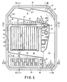
- the apparatus comprises a box-shaped body 20 which can be molded from plastic and which is closed frontally by a cover 28 made of transparent plastic, connected to the body 20, for example, by means of rivets 30 with elastic snap-fastening. Between the body 20 in the form of a box and the transparent cover 28 is inserted a rigid sheet 31, for example of cardboard cut to the punch, which determines a rolling surface for the balls.
- the box-shaped body 20 has connections 21 on the back, to which legs 29 are connected which are capable of assuming an active position and a neutralized position.
- the activity position (FIG. 2)
- the free ends of the legs 29 and the lower dorsal edge 23 of the body 20 can press on a surface P, for example of a ta ble, thereby maintaining the box-shaped body 20 in an inclined position corresponding to the condition of use.
- the value of this inclination is chosen, also depending on the characteristics of the materials used, so as to give rise to an appropriate rolling speed of the balls used for the composition.
- the neutralized position (FIG. 3)
- the tabs 29 are brought closer to the body 20 and allow the device to be stored with a reduced bulk.
- the tabs 29 are articulated by means of holes in the form of buttonholes on flattened pins 22 provided on the connectors 21 and on which the tabs can rotate to reach the neutralized position, while in the position of activity they can be slightly pushed into the fittings 21 thus coupling to the flattened trunnions 22, and then they can no longer rotate and ensure the stability of the support until the moment when they are pulled outwards in order to be able to do them turn and return them to the neutralized position.
- a composition plate 38 In the box-shaped body 20 is mounted a composition plate 38, preferably made of transparent plastic, which has a series of projecting guides 39 rectilinear, parallel and equidistant, arranged along the lines of greatest inclination of the body 20 when the latter is in the condition of use, and a transverse wall 40 extending at the upper end of the projecting guides 39.
- the latter subdivide the composition plate 38 into a plurality of parallel columns, which have a width a little more larger than the diameter of the beads with which it is intended to form the mosaic, and a length equal to several times the diameter of these beads.
- the entire thickness of the box-shaped body 20 is used, thus obtaining, albeit with a space requirement. reduced, a sufficient capacity tank.
- an upper magazine 32 for balls B to be stored in columns Projecting walls, presented by the transparent cover 28 on its face turned towards the box-shaped body 20, delimit on the rolling surface 31 different regions, and more particularly: an upper magazine 32 for balls B to be stored in columns, a rejection passage 33 extending from the upper part of the apparatus to the lower reservoir 24, a launch corridor 35 which communicates with the lowest point of the upper magazine 32 through a mouth 34 and which s extends along the transverse wall 40 of the composition plate 38, a return passage 36 which, starting from the end of the launch passage 35 descends next to the composition plate, passes along its lower edge and opens into the lower tank 24, and finally a large loading passage 37 connecting the lower reservoir 24 to the upper magazine 32.
- the upper magazine 32 is delimited by an inclined lower wall 32 'through which the mouth 34 of the launch passage opens; all the balls B contained in the magazine are supported on the lower wall 32 ′ and on the lowest ball, engaged in the mouth 34, spontaneously arranging themselves in order by superimposed rows.
- the magazine 32 has no wall bounding towards the loading passage 37, and this characteristic prevents any possibility of engorgement in the feeding of the balls, which inevitably would take place in the case of a usual configuration in the form of a hopper.
- the magazine 32 also has wall sections 32 "opposite the bottom wall 31, which extend parallel to the latter, and side wall sections 32 ° inclined by 60 ° relative to the walls 32 'and.
- the periphery of the store reproduces the spontaneous arrangement of the balls contained therein, by using the space in the best way and by favoring an ordered arrangement of the balls.
- the two wall sections 32 opposite the bottom wall 32 'form a step the height of which is equal to that of a row of balls, in order to increase the use of space. without give rise to disturbances in the regularity of arrangement of the balls.
- the inclination of the lower wall 32 ′ with respect to a horizontal line of the rolling surface 31 is chosen, also depending on the materials used and the inclination of the body 20 in its operational condition, so that the balls B contained in the magazine 32 remain supported on each other with sufficient stability and tend to roll regularly, one row after another, towards the mouth 34, as the balls are withdrawn from the magazine through said mouth.
- the inclination shown is suitable, under the conditions illustrated by way of example, when the rolling surface 31 is made of metallized cardboard and the balls are made of plastic.
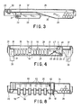
- the mouth of the rejection passage 33 is located opposite the mouth 34 of the launch corridor 35 and is normally closed by a fin 42 presented by a lever 41 (FIG. 6), mounted on a pivot 25 of the body 20 box shaped and. provided with an unloading control button 43.
- a return spring 44 maintains the lever 41 with the fin 42 in the closed position of the mouth of the rejection passage 33.
- the pusher 43 projects from the cover 28 and it can be pressed to temporarily move the fin 42 in a position in which it does not occlude the rejection passage 33. By this maneuver, the balls contained in the upper magazine 32 are allowed to roll by gravity, one after the other, through the rejection passage 33, towards the lower reservoir 24, as long as the pusher 43 is kept lowered.
- the launch device At the mouth of the launch corridor 35 is installed the launch device.
- This device comprises a launching member 46 and a retaining member 47, supported by a lever 45 (FIG. 4) mounted on a pivot 26 formed on the box-shaped body 20.
- the lever 45 is provided with a control arm 48 which ends in an elastically flexible part 49 constituting a return spring which normally retains the lever 45 in the position illustrated in FIG. 4.
- the members 46 and 47 are located on either side of the em opening 34 of launch corridor 35, is they. retain a ball C which, being located at the bottom of the upper magazine 32, is penetrated by gravity into the mouth 34.
- a control lever 50 ( Figure 5), mounted on a pivot 27 of the box-shaped body 20 and provided with a control pusher 52.
- the pusher 52 projects from the cover 28 and it can be pressed or, to be more precise, struck, to lower the lever 50 and consequently oscillate the lever 45 against the action of the spring 49.
- the retaining member 47 is made to disappear under the rolling plate 31, while the launching member 46 advances and prints an impulse to ball C by rolling it along the launch corridor 35. If the ball is not intercepted, it reaches the end of the launch corridor 35 and passes through the return corridor 36, thereby returning along the latter to the lower tank 24.
- This maneuver is used to exclude n columns the balls which one does not intend to use; moreover, in this way it is possible to recover and reintroduce into the tank 24 the balls which for some reason have not been placed in a column.
- the control lever 50 acts with a considerable multiplication, so that a small stroke of the pusher 52 is sufficient to impart to the lever 45 a sufficient pulse for the launching of the ball. Therefore it facilitates the use of the device, in consideration of the fact that the pusher 52 must be struck many times during each composition; in addition, it promotes a launch of the balls in rapid succession.
- the column setting device is disposed between the composition plate 38 and the bottom of the body 20; it includes column setting lever 53, one for each column of the composition tray.
- Each column setting lever 53 (FIG. 7) is pivoted on an elastically deformable support 57, applied to the box-shaped body 20, and it is subjected to the action of a return spring 58 which normally retains the lever in the position illustrated in Figure 7.
- Each lever 53 has a deflection fin 54 which, in the rest condition, is so killed between the rolling surface 31 and the bottom of the body 20, in correspondence with the launch corridor 35 (but without penetrating into the latter), and more distant from the transverse wall 40 of the composition plate 38 than from the opposite wall of the corridor 35.
- Each fin 54 forms an inclined ramp (FIG.
- each column setting lever 53 has a control pusher 55.
- each column setting lever 53 also has a shutter fin 56 which normally projects from the composition plate 38 at the lower end of the corresponding column and retains the balls E contained in this column, which, in this way, remain aligned one on the other between the projecting guides 39.
- All the control push-buttons 55 of the various column setting levers 53 are arranged so as to form a keyboard 59, and they are each marked, for example, by a number from 1 to 12, while the same numbers are printed on the head of the corresponding columns of the composition plate 38, in order to facilitate the determination of the pusher corresponding to each column.
- the levers 53 have alternately two different lengths, so that their pushers 55 forming the keyboard 59 are moved on two levels ( Figures 1 and 7), and they can be arranged with a spacing such as to allow easy maneuvering.
- a stroke limiting member 60 (FIGS. 7 and 8) is arranged, sliding transversely in the box-shaped body 20, held in the position illustrated by a return spring 63 and movable by means of a handle. control protruding from the cover 28.
- the limiting member 60 has lugs 62 capable of opposing the pushers 55 and, normally, of limiting the stroke to the value sufficient to control the deflection fins 54.
- the pins 62 cease to oppose the pushers and limit the stroke; it is then possible to lower a pusher 55 further, until the shutter fin 56 disappears under the composition plate 38.
- the lower end of a column is released from the composition plate 38, and this column is then abandoned by the balls E which were contained therein, which descend into the return passage 36 and collect in the lower tank 24.
- the apparatus according to the invention is used as follows. In the beginning, a certain number of balls A of different colors is contained in the lower reservoir 24. By tilting the apparatus in the direction opposite to that of its inclination in the condition of use, at least a part of the balls is transferred, through the loading passage 47, at the upper magazine 32, in which these balls B resemble each other in order by pressing one on the other, while the lowest of them, ball C, is introduced in the mouth 34 of the launch corridor 35 and remains stationary there, retained between the fin 42, the launching member 46 and the retaining member 47.
- the composition operation begins from this condition.
- the ball C is of an unwanted color, it can be rejected by striking the pusher 52 without actuating any column setting pusher; in this case, the ball travels through the entire launch corridor 35 and then the return corridor 36, and returns to the lower reservoir 24. If several balls have to be rejected, this operation can be repeated several times or alternatively, one can press the pusher 43 to make the rejection passage 33 temporarily accessible.
- the cover 28 has, in correspondence with the launching corridor 35, a projecting part delimited by an inclined wall 28 ' .
- this inclined wall 28 ′ also has, in successive parts each of which corresponds to one of the columns of the composition plate, a transverse inclination, in order to make the diverted ball rebound in the direction of the corresponding column.
- the cover has wall portions 28 "oriented towards the corresponding projecting guides 39, in order to completely separate the different columns also in correspondence with the projecting part of the cover.
- the cover 28 extends parallel to the composition plate at a distance from the latter a little greater than the diameter of the balls used. Thanks to all of these measures, the chosen columns are conveyed, without uncertainty, either the balls launched slowly or those that are launched faster.
- the balls of the chosen colors can be directed to the different columns of the composition tray 38, by composing thus on the tray 38 a mosaic of beads forming the desired design.
- the column in which the error has occurred can be emptied by actuating the corresponding pusher 55 after having moved, by means of the control handle 61, the limiting member 60, and therefore making it disappear under the rolling surface 31 the closing fin 56 corresponding to the column to be emptied.
- a cardboard 64 carrying a drawing prepared in advance can be inserted into a corresponding slot located between the composition plate 38 and the bottom of the body 20.
- the cardboard 64 is visible through the composition plate 38, which, as already mentioned - dit is transparent, and guides the design composition of the beads, making it much easier to produce.
- a cavity 65 is provided in the corresponding part of the body 20.
- the balls B contained in the upper magazine 32 are not sufficient to complete the composition, other balls can be moved from position A to position B, by tilting the appliance again in the direction opposite to the direction of use. . This does not involve the destruction of the composition already carried out, because during this operation the balls contained in the columns of the composition plate 38 are stopped by the transverse wall 40 and cannot leave the respective columns.
- the composition plate 38 is installed with a slightly smaller inclination than that of the rolling surface 31, as illustrated in Figure 7.
- the upper magazine 32 can be emptied quickly by actuating the pusher 43 and thus releasing the movement in the rejection passage 33.
- the legs 29 may be constructively separated from the body 20 and be applied to the latter for the use of the device and detached for storage.
- Different devices from those which have been described could be applied to launch the balls, to divert them towards the columns in which they must be inserted and to reject the unwanted balls.
- the emptying of the columns could be controlled by means of pushers separate from the column setting pushers.
Landscapes
- Engineering & Computer Science (AREA)
- Multimedia (AREA)
- Pinball Game Machines (AREA)
- Toys (AREA)
- Ropes Or Cables (AREA)
- Display Devices Of Pinball Game Machines (AREA)
- Yarns And Mechanical Finishing Of Yarns Or Ropes (AREA)
- Adornments (AREA)
Priority Applications (1)
| Application Number | Priority Date | Filing Date | Title |
|---|---|---|---|
| AT86200074T ATE41875T1 (de) | 1985-01-25 | 1986-01-16 | Apparat zum maschinellen zusammensetzen eines mosaikbildes aus kuegelchen. |
Applications Claiming Priority (2)
| Application Number | Priority Date | Filing Date | Title |
|---|---|---|---|
| IT67065/85A IT1182377B (it) | 1985-01-25 | 1985-01-25 | Apparecchio per comporre meccanicamente un disegno a mosaico di palline |
| IT6706585 | 1985-01-25 |
Publications (3)
| Publication Number | Publication Date |
|---|---|
| EP0193217A2 true EP0193217A2 (de) | 1986-09-03 |
| EP0193217A3 EP0193217A3 (en) | 1987-05-27 |
| EP0193217B1 EP0193217B1 (de) | 1989-04-05 |
Family
ID=11299300
Family Applications (1)
| Application Number | Title | Priority Date | Filing Date |
|---|---|---|---|
| EP86200074A Expired EP0193217B1 (de) | 1985-01-25 | 1986-01-16 | Apparat zum maschinellen Zusammensetzen eines Mosaikbildes aus Kügelchen |
Country Status (7)
| Country | Link |
|---|---|
| US (1) | US4662846A (de) |
| EP (1) | EP0193217B1 (de) |
| JP (1) | JPH0677617B2 (de) |
| AT (1) | ATE41875T1 (de) |
| DE (1) | DE3662643D1 (de) |
| ES (1) | ES296402Y (de) |
| IT (1) | IT1182377B (de) |
Cited By (1)
| Publication number | Priority date | Publication date | Assignee | Title |
|---|---|---|---|---|
| GB2214441A (en) * | 1988-01-26 | 1989-09-06 | Valley Holding Company Inc | Ball control apparatus |
Families Citing this family (22)
| Publication number | Priority date | Publication date | Assignee | Title |
|---|---|---|---|---|
| US4979739A (en) * | 1988-01-26 | 1990-12-25 | Kidde Recreation Products, Inc. | Ball return control apparatus |
| US4938472A (en) * | 1989-01-23 | 1990-07-03 | Gould Murray J | Game with stacking pieces on inclined surfaces |
| US5803451A (en) * | 1992-10-02 | 1998-09-08 | Rlt Acquisition, Inc. | Arcade game having multiple score indicators |
| US7766329B1 (en) | 1992-10-02 | 2010-08-03 | Sierra Design Group | Wheel indicator and ticket dispenser apparatus |
| US7832727B1 (en) | 1992-10-02 | 2010-11-16 | Bally Gaming Inc. | Illuminated wheel indicators |
| US5292127C1 (en) * | 1992-10-02 | 2001-05-22 | Arcade Planet Inc | Arcade game |
| USD349303S (en) | 1993-01-22 | 1994-08-02 | Kinderworks Corporation | Game board |
| JP2590049B2 (ja) * | 1994-10-24 | 1997-03-12 | タキゲン製造株式会社 | 掛金装置 |
| JP2590048B2 (ja) * | 1994-10-24 | 1997-03-12 | タキゲン製造株式会社 | 掛金装置 |
| US5697611A (en) * | 1995-01-17 | 1997-12-16 | Rlt Acquisition, Inc. | Redemption-type arcade game with game token return |
| US5667217A (en) * | 1995-08-29 | 1997-09-16 | Rlt Acquisition, Inc. | Roll-down arcade game |
| US5769424A (en) * | 1996-09-24 | 1998-06-23 | Rlt Acquisition, Inc. | Arcade game for stacking directed playing pieces |
| US5971762A (en) * | 1999-02-08 | 1999-10-26 | Mckenna; Paul A. | Bead-based drop art book |
| US7775870B2 (en) | 2003-11-21 | 2010-08-17 | Sierra Design Group | Arcade game |
| US7823883B1 (en) | 2008-02-29 | 2010-11-02 | Bally Gaming Inc. | Wheel indicator and ticket dispenser apparatus |
| JP4721371B2 (ja) * | 2008-10-17 | 2011-07-13 | タキゲン製造株式会社 | ファスナー金具用調整受金具 |
| US8403329B2 (en) * | 2010-03-18 | 2013-03-26 | Radomir Krickovic | Gaming device for pellet guns |
| USD791879S1 (en) * | 2015-05-28 | 2017-07-11 | Fikst, Llc | Gift card maze puzzle |
| US10818196B2 (en) | 2017-06-15 | 2020-10-27 | Paul Garrett Boswell | Mechanical computer with repositionable components |
| JP6611100B2 (ja) | 2017-08-31 | 2019-11-27 | 株式会社コナミアミューズメント | ゲーム装置 |
| US20220161093A1 (en) * | 2018-11-30 | 2022-05-26 | Gene Wilhelmi | Speed and Agility Game Platform |
| JP1663039S (de) * | 2019-12-11 | 2020-07-06 |
Family Cites Families (13)
| Publication number | Priority date | Publication date | Assignee | Title |
|---|---|---|---|---|
| US1533854A (en) * | 1924-05-12 | 1925-04-14 | Eugene D Gray | Game apparatus |
| US2378983A (en) * | 1944-01-03 | 1945-06-26 | William J Conwell | Game |
| US2782037A (en) * | 1952-04-16 | 1957-02-19 | Rovira Alberto Grau | Surface projectile ball game |
| US2863667A (en) * | 1955-04-25 | 1958-12-09 | Willard E Batts | Game device |
| DE1164897B (de) * | 1960-07-18 | 1964-03-05 | Max Ernst | Geschicklichkeitsspielgeraet |
| US3278187A (en) * | 1964-02-26 | 1966-10-11 | Parker Brothers Inc | Game machine employing multi-state swinging gates |
| US3390471A (en) * | 1965-04-30 | 1968-07-02 | E S R Inc | Binary digital computer |
| US3388483A (en) * | 1966-07-21 | 1968-06-18 | Joseph A. Weisbecker | Computer-type game and teaching aid |
| US3807737A (en) * | 1971-12-14 | 1974-04-30 | Marvin Glass & Associates | Game apparatus |
| US3853318A (en) * | 1973-04-24 | 1974-12-10 | Placo Prod Co | Combination dart and pinball apparatus |
| US3994076A (en) * | 1975-09-30 | 1976-11-30 | Bertman Martha O | Modular computer teaching device |
| JPS5535020Y2 (de) * | 1978-09-18 | 1980-08-19 | ||
| IT1155576B (it) * | 1982-07-27 | 1987-01-28 | Quercetti Alessandro & Co | Gioco didattico di selezione di traiettorie percorse da palline |
-
1985
- 1985-01-25 IT IT67065/85A patent/IT1182377B/it active
-
1986
- 1986-01-03 US US06/818,597 patent/US4662846A/en not_active Expired - Lifetime
- 1986-01-15 ES ES1986296402U patent/ES296402Y/es not_active Expired - Fee Related
- 1986-01-16 DE DE8686200074T patent/DE3662643D1/de not_active Expired
- 1986-01-16 AT AT86200074T patent/ATE41875T1/de active
- 1986-01-16 EP EP86200074A patent/EP0193217B1/de not_active Expired
- 1986-01-24 JP JP61014614A patent/JPH0677617B2/ja not_active Expired - Fee Related
Cited By (2)
| Publication number | Priority date | Publication date | Assignee | Title |
|---|---|---|---|---|
| GB2214441A (en) * | 1988-01-26 | 1989-09-06 | Valley Holding Company Inc | Ball control apparatus |
| GB2214441B (en) * | 1988-01-26 | 1991-05-08 | Valley Holding Company Inc | Ball return control apparatus |
Also Published As
| Publication number | Publication date |
|---|---|
| US4662846A (en) | 1987-05-05 |
| JPS61176375A (ja) | 1986-08-08 |
| EP0193217B1 (de) | 1989-04-05 |
| EP0193217A3 (en) | 1987-05-27 |
| ES296402U (es) | 1988-05-16 |
| DE3662643D1 (en) | 1989-05-11 |
| IT1182377B (it) | 1987-10-05 |
| ES296402Y (es) | 1990-02-16 |
| JPH0677617B2 (ja) | 1994-10-05 |
| IT8567065A1 (it) | 1986-07-25 |
| IT8567065A0 (it) | 1985-01-25 |
| ATE41875T1 (de) | 1989-04-15 |
Similar Documents
| Publication | Publication Date | Title |
|---|---|---|
| EP0193217B1 (de) | Apparat zum maschinellen Zusammensetzen eines Mosaikbildes aus Kügelchen | |
| CA1318610C (fr) | Dispositif de stockage et de distribution d'objets | |
| EP0786939B1 (de) | Maschine zur automatischen herstellung von fleisch- und/oder gemüse-spiessen | |
| EP0101624B1 (de) | Unterrichtspiel durch die Auswahl der Bahnen von Kugeln | |
| US3797828A (en) | Launcher and targets having overload mechanism | |
| FR2680699A1 (fr) | Rampe a trajets multiples pour billard electrique. | |
| FR2525484A1 (fr) | Billard electrique | |
| FR2715811A1 (fr) | Table à jouer. | |
| FR2669835A1 (fr) | Jeu a circulation de billes. | |
| FR2475405A1 (fr) | Appareil de jeu a distributeur de disques | |
| CH655856A5 (fr) | Objet de divertissement constitue par un labyrinthe transparent en trois dimensions. | |
| EP2896439A1 (de) | TISCHFUßBALLSPIEL, UMGANGSSPRACHLICH TISCHKICKER GENANNT, DAS SCHIEßELEMENTE UMFASST, UND ENTSPRECHENDES SCHIEßELEMENT | |
| JP5049222B2 (ja) | 盤面部品、演出装置、遊技盤ユニット、及びパチンコ遊技機 | |
| EP0824945B1 (de) | Spielbrett | |
| US5529206A (en) | Game machine having automatic gift ejecting function | |
| CH177624A (fr) | Jeu de des semi-automatique. | |
| US960071A (en) | Puzzle. | |
| JPH0742461Y2 (ja) | パチンコ機の入賞装置 | |
| JP4709559B2 (ja) | 景品取得ゲーム機 | |
| FR2511167A1 (fr) | Dispositif pour recuperer des cartes rangees de maniere aleatoire et capsule de stockage de cartes a bord code | |
| CH685859A5 (fr) | Jeu éducatif pour enfants visant à encourager le tri des ordures ménagères | |
| US1087390A (en) | Toy. | |
| FR2479696A1 (fr) | Jeu comportant une table et une bille dont on peut commander la trajectoire | |
| BE418762A (de) | ||
| JP2002172269A (ja) | ゲーム装置 |
Legal Events
| Date | Code | Title | Description |
|---|---|---|---|
| PUAI | Public reference made under article 153(3) epc to a published international application that has entered the european phase |
Free format text: ORIGINAL CODE: 0009012 |
|
| AK | Designated contracting states |
Kind code of ref document: A2 Designated state(s): AT BE CH DE FR GB LI LU NL SE |
|
| RTI1 | Title (correction) | ||
| PUAL | Search report despatched |
Free format text: ORIGINAL CODE: 0009013 |
|
| AK | Designated contracting states |
Kind code of ref document: A3 Designated state(s): AT BE CH DE FR GB LI LU NL SE |
|
| 17P | Request for examination filed |
Effective date: 19871118 |
|
| 17Q | First examination report despatched |
Effective date: 19880509 |
|
| GRAA | (expected) grant |
Free format text: ORIGINAL CODE: 0009210 |
|
| AK | Designated contracting states |
Kind code of ref document: B1 Designated state(s): AT BE CH DE FR GB LI LU NL SE |
|
| PG25 | Lapsed in a contracting state [announced via postgrant information from national office to epo] |
Ref country code: SE Effective date: 19890405 Ref country code: NL Effective date: 19890405 Ref country code: AT Effective date: 19890405 |
|
| REF | Corresponds to: |
Ref document number: 41875 Country of ref document: AT Date of ref document: 19890415 Kind code of ref document: T |
|
| REF | Corresponds to: |
Ref document number: 3662643 Country of ref document: DE Date of ref document: 19890511 |
|
| GBT | Gb: translation of ep patent filed (gb section 77(6)(a)/1977) | ||
| NLV1 | Nl: lapsed or annulled due to failure to fulfill the requirements of art. 29p and 29m of the patents act | ||
| PG25 | Lapsed in a contracting state [announced via postgrant information from national office to epo] |
Ref country code: LU Free format text: LAPSE BECAUSE OF NON-PAYMENT OF DUE FEES Effective date: 19900131 Ref country code: BE Effective date: 19900131 |
|
| PLBE | No opposition filed within time limit |
Free format text: ORIGINAL CODE: 0009261 |
|
| STAA | Information on the status of an ep patent application or granted ep patent |
Free format text: STATUS: NO OPPOSITION FILED WITHIN TIME LIMIT |
|
| 26N | No opposition filed | ||
| BERE | Be: lapsed |
Owner name: ALESSANDRO QUERCETTI & C. FABBRICA GIOCATTOLI FOR Effective date: 19900131 |
|
| PGFP | Annual fee paid to national office [announced via postgrant information from national office to epo] |
Ref country code: DE Payment date: 20010228 Year of fee payment: 16 |
|
| PGFP | Annual fee paid to national office [announced via postgrant information from national office to epo] |
Ref country code: CH Payment date: 20010326 Year of fee payment: 16 |
|
| PGFP | Annual fee paid to national office [announced via postgrant information from national office to epo] |
Ref country code: FR Payment date: 20011228 Year of fee payment: 17 |
|
| REG | Reference to a national code |
Ref country code: GB Ref legal event code: IF02 |
|
| PG25 | Lapsed in a contracting state [announced via postgrant information from national office to epo] |
Ref country code: LI Free format text: LAPSE BECAUSE OF NON-PAYMENT OF DUE FEES Effective date: 20020131 Ref country code: CH Free format text: LAPSE BECAUSE OF NON-PAYMENT OF DUE FEES Effective date: 20020131 |
|
| PGFP | Annual fee paid to national office [announced via postgrant information from national office to epo] |
Ref country code: GB Payment date: 20020314 Year of fee payment: 17 |
|
| PG25 | Lapsed in a contracting state [announced via postgrant information from national office to epo] |
Ref country code: DE Free format text: LAPSE BECAUSE OF NON-PAYMENT OF DUE FEES Effective date: 20020801 |
|
| REG | Reference to a national code |
Ref country code: CH Ref legal event code: PL |
|
| PG25 | Lapsed in a contracting state [announced via postgrant information from national office to epo] |
Ref country code: GB Free format text: LAPSE BECAUSE OF NON-PAYMENT OF DUE FEES Effective date: 20030116 |
|
| GBPC | Gb: european patent ceased through non-payment of renewal fee | ||
| PG25 | Lapsed in a contracting state [announced via postgrant information from national office to epo] |
Ref country code: FR Free format text: LAPSE BECAUSE OF NON-PAYMENT OF DUE FEES Effective date: 20030930 |
|
| REG | Reference to a national code |
Ref country code: FR Ref legal event code: ST |