EP0193532B1 - Vorrichtung für einzelteile in form eines pfostens - Google Patents
Vorrichtung für einzelteile in form eines pfostens Download PDFInfo
- Publication number
- EP0193532B1 EP0193532B1 EP85900245A EP85900245A EP0193532B1 EP 0193532 B1 EP0193532 B1 EP 0193532B1 EP 85900245 A EP85900245 A EP 85900245A EP 85900245 A EP85900245 A EP 85900245A EP 0193532 B1 EP0193532 B1 EP 0193532B1
- Authority
- EP
- European Patent Office
- Prior art keywords
- strap
- pole
- straps
- attachment
- point
- Prior art date
- Legal status (The legal status is an assumption and is not a legal conclusion. Google has not performed a legal analysis and makes no representation as to the accuracy of the status listed.)
- Expired
Links
- 239000002184 metal Substances 0.000 claims description 13
- 239000000463 material Substances 0.000 claims description 9
- 229920002994 synthetic fiber Polymers 0.000 claims description 3
- 239000012790 adhesive layer Substances 0.000 claims 1
- 230000006378 damage Effects 0.000 description 9
- 238000000034 method Methods 0.000 description 4
- 238000004026 adhesive bonding Methods 0.000 description 2
- 238000005286 illumination Methods 0.000 description 1
- 239000007769 metal material Substances 0.000 description 1
- 238000012986 modification Methods 0.000 description 1
- 230000004048 modification Effects 0.000 description 1
- 230000035515 penetration Effects 0.000 description 1
- 230000001681 protective effect Effects 0.000 description 1
- 239000007787 solid Substances 0.000 description 1
Images

Classifications
-
- E—FIXED CONSTRUCTIONS
- E01—CONSTRUCTION OF ROADS, RAILWAYS, OR BRIDGES
- E01F—ADDITIONAL WORK, SUCH AS EQUIPPING ROADS OR THE CONSTRUCTION OF PLATFORMS, HELICOPTER LANDING STAGES, SIGNS, SNOW FENCES, OR THE LIKE
- E01F9/00—Arrangement of road signs or traffic signals; Arrangements for enforcing caution
- E01F9/60—Upright bodies, e.g. marker posts or bollards; Supports for road signs
- E01F9/623—Upright bodies, e.g. marker posts or bollards; Supports for road signs characterised by form or by structural features, e.g. for enabling displacement or deflection
- E01F9/631—Upright bodies, e.g. marker posts or bollards; Supports for road signs characterised by form or by structural features, e.g. for enabling displacement or deflection specially adapted for breaking, disengaging, collapsing or permanently deforming when deflected or displaced, e.g. by vehicle impact
- E01F9/638—Upright bodies, e.g. marker posts or bollards; Supports for road signs characterised by form or by structural features, e.g. for enabling displacement or deflection specially adapted for breaking, disengaging, collapsing or permanently deforming when deflected or displaced, e.g. by vehicle impact by connection of stud-and-socket type, e.g. spring-loaded
Definitions
- the present invention relates to a device for pole-shaped elements, intended to reduce the risk of damage caused by collision with a vehicle.
- Various types of pole-shaped elements exist adjacent to a road surface, utilized to support illumination, signs, traffic signals, electrical and telecommunication cables, and also utilized for other purposes. When such pole-shaped elements are hit by a vehicle, considerable damage can occur, both material damage as well as injuries to persons. This fact is well known, and various solutions, intended to reduce the extent of the damage, have also been proposed.
- pole-shaped members with a fractural impression adjacent to the ground surface, in order to facilitate disengagement from the base foundation, and it is further desirable that the removed pole-shaped element, if possible, should perform a movement over a colliding vehicle, and fall down behind same.
- attempts have been made to arrange previously known types of pole-shaped elements as lattice structures having sections with a relatively small cross-section, in order to provide a pole which relatively softly can be plastically deformed in a collision, and thereby reduce the movement of a vehicle during a longer distance, i.e. in order to accomplish a slower braking operation.
- the increase in braking distance thus accomplished will be marginal, and resulting damage will still be excessive.
- DE-A-2 445 842 discloses a device for a pole-shaped element, whereby the pole-shaped element is attached to a base adjacent to a ground plane in such a way, that it is released in a region adjacent to the base when influenced by a collision.
- This device further comprises a flexible element (a cable, equipped with a spring) arranged within and along substantially the entire length of the pole-shaped member between a first point of attachment adjacent to the upper portion of the pole-shaped element and a second point of attachment at the base, and arranged to take up a total and substantially non-resilient longitudinal extension which substantially exceeds the distance between the attachment points when the pole-shaped element is sheared off or released from the base, as well as restricting the distance which the pole-shaped element is thrown towards and past a colliding vehicle.
- a flexible element a cable, equipped with a spring
- the device according to the present invention can be used for pole-shaped elements having a non-solid cross-section, and is particularly suitable for use in connection with pole-shaped elements having a tubular cross-section, even though other cross-sectional configurations can be utilized.
- the object of the present invention is to disclose a possibility to slow down the speed of a colliding vehicle over a relatively long distance, and further to remove previously existing risks for injuries against a third party caused by a pole thrown over a colliding vehicle, and the uncontrolled fall at a distance from previous location. Damage on the vehicle and the pole, as well as light fittings or similar supported by the pole, will further be restricted to a minimum.
- pole-shaped members can be arranged considerably simpler and cheaper than previously known elements having plastically deformable properties, i.e. previously known pole-shaped elements which during a collision by means of plastical deformation facilitate that the speed of a colliding vehicle is slowed down during a certain distance of travel.
- the device according to the present invention is intended for a pole-shaped element, which is attached against a base adjacent to a ground plane in such a way, that it is released in a region adjacent to the base when influenced by a collision, comprising a flexible element arranged within and along substantially the entire length of the pole-shaped element between a first point of attachment adjacent to the upper portion of the pole-shaped element and a second point of attachment at the base and arranged to take up a total and substantially non-resilient longitudinal extension which substantially exceeds the distance between the attachment points when the pole-shaped element due to influence from a collision is sheared off or released from the base, as well as restricting the distance which the pole-shaped element is thrown towards and past a colliding vehicle, and it is mainly characterised in that the flexible element consists of one or a number of flexible straps, preferably of a woven material, and that the strap(s) has/have been arranged to catch the vehicle colliding with the pole-shaped element.
- pole-shaped supporting element 1 having a tubular cross-section, attached to a base 2 adjacent to a ground plane 3.
- the pole-shaped supporting element 1 surrounds a strap 4, preferably being a woven flexible strap of a synthetic fibre material or similar, which in relation to one end portion is attached at the upper portion of the pole-shaped supporting element 1, and having the opposed end portion arranged wound on a roll-shaped member 5, located below the ground plane 3 adjacent to the base 2.
- Said roll-shaped member 5 further includes a brake device which facilitates unwinding of the wound portion of the strap 4 from the roll-shaped member 5 with a predetermined braking force.
- the pole-shaped supporting element 1 is attached to the base 2 in such a way, that it can be released from the base 2 when made subject to a collision with an approaching vehicle.
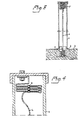
- Fig. 2 The method according to which the device described with reference to Fig. 1 acts when the pole-shaped supporting element 1 is subjected to a collision with a vehicle is shown in Fig. 2.
- a vehicle 6 hits the pole-shaped supporting element 1 in the region adjacent to the point of attachment against the base 2, the pole-shaped supporting element 1 is released from the base 2, and the strap 4 is unwound from the roll-shaped member 5, as indicated by arrows.
- said unwounding is performed while maintaining a braking force, and said force can either be continuous during unwinding, or advantageously be arranged to be continuously increased, i.e. with a continuously increasing braking action during the unwinding operation.
- the pole-shaped supporting member 1 Due to the force applied against the lower portion from the colliding vehicle 6, the pole-shaped supporting member 1, when released from the base 2, will fall in direction towards the direction of travel for the vehicle with its upper portion, and since the outer end portion of the strap 4 wound on the roll-shaped member 5 is rigidly attached to said member 5, unwinding can only be performed during a certain predetermined distance, e.g. corresponding to the distance shown in fig. 2, but also a longer unwinding distance can be used.
- the strap 4 thus acts as a catching member for the colliding vehicle 6, but also as a restricting member for the pole-shaped supporting element 1, which thus is held within an area adjacent to the base 2 and the location for the collision, whereby the risk for injuries on other vehicles, or persons located nearby, substantially completely is eliminated.
- FIG. 3 An example of an alternative embodiment is shown in fig. 3, in which previously discussed roll-shaped member 5 with associated brake device has been replaced by a metal strip 7 bent in zig-zag-shape, having one end portion arranged rigidly attached below the ground plane 3 at the base 2, and with the other end portion arranged attached to the flexible strap 4, which is arranged surrounded by the pole-shaped supporting element 1.
- a second and correspondingly arranged metal strip 7' is arranged at the upper portion of the pole-shaped element 1, having a first end portion attached against the pole-shaped supporting element 1, and with the other end portion attached to the flexible strap 4.
- the zig-zag-shaped metal strips 7, 7' are chosen with regard to material thickness and cross-sectional configuration in such a way, that they act as a suitable braking element when same during a collision are stretched and reshaped into a substantially longitudinally extending configuration.
- the thickness and/or width of the metal strips 7, 7' can be varied between said two points of attachment, in order to accomplish a step by step or continuously varied force necessary for extension of same from the original zig-zag-shape.
- the flexible strap 4 obviously can be directly attached against the base 2, or the upper portion of the pole-shaped supporting element 1, and that thus only one of the metal strips 7, 7' shown is required.
- a metal strip 7' arranged adjacent to the upper portion of a pole-shaped element 1 results in the possibility to accomplish considerably longer lengths of zig-zag extending metal strips 7' than what normally is possible adjacent to the base 2, and attachment and location of such a metal strip 7' in a position surrounded by the pole-shaped supporting element 1 thus offers a possibility to use zig-zag-shaped metal strips 7' having a longitudinal extension which is only restricted by the length of the pole-shaped supporting element 1, i.e.
- fig. 4 intends to disclose a further example of an embodiment, in which the flexible strap 4 only is shown adjacent to one end portion of a pole-shaped supporting element 1.
- the strap 4 extends in adjacently located loops, having a centrally located joining member 8 for the loops of the strap.
- Said joining member 8 would in its simplest form comprise of stitches joining the loops, but could also comprise of a member extending through the strap 4, which is joined to the strap 4 at each point of penetration, or by means of one or two straps, which are joined to the edge portions of the loops in the strap, e.g. by means of stitches.
- stitches for previously discussed attachment also.
- other means of attachment can be used, as well as a glueing method.
- adjacently located loops of the strap can be internally directly attached with adjacent surfaces against each other, and the established joint is always arranged in such a way, that it may be released at a predetermined applied force, in order to accomplish a substantially completely longitudinally extending flexible strap 4.
- utilized straps 4 are advantageously arranged as woven straps of a synthetic fibre material, since such straps 4 result in desired properties, but also other materials may obviously be used, and also metallic materials.
- the term strap is not intended to disclose only rectangular cross-sectional configuration, even though such a configuration often is advantageous, since also other cross-sectional configurations can be used, while maintaining the important and characteristic features of the invention.
Landscapes
- Engineering & Computer Science (AREA)
- Architecture (AREA)
- Civil Engineering (AREA)
- Structural Engineering (AREA)
- Refuge Islands, Traffic Blockers, Or Guard Fence (AREA)
- Linear Motors (AREA)
- Magnetic Resonance Imaging Apparatus (AREA)
- Road Signs Or Road Markings (AREA)
- Load-Engaging Elements For Cranes (AREA)
Claims (10)
Priority Applications (1)
| Application Number | Priority Date | Filing Date | Title |
|---|---|---|---|
| AT85900245T ATE37056T1 (de) | 1983-12-13 | 1984-12-12 | Vorrichtung fuer einzelteile in form eines pfostens. |
Applications Claiming Priority (2)
| Application Number | Priority Date | Filing Date | Title |
|---|---|---|---|
| SE8306871A SE445656B (sv) | 1983-12-13 | 1983-12-13 | Anordning vid ett stolpformigt element der ett flexibelt band er anordnat, vars lengd vesentligen overstiger lengden mellan dess infestningspunkter i det stolpformiga elementet och fundamentet |
| SE8306871 | 1983-12-13 |
Publications (2)
| Publication Number | Publication Date |
|---|---|
| EP0193532A1 EP0193532A1 (de) | 1986-09-10 |
| EP0193532B1 true EP0193532B1 (de) | 1988-09-07 |
Family
ID=20353701
Family Applications (1)
| Application Number | Title | Priority Date | Filing Date |
|---|---|---|---|
| EP85900245A Expired EP0193532B1 (de) | 1983-12-13 | 1984-12-12 | Vorrichtung für einzelteile in form eines pfostens |
Country Status (8)
| Country | Link |
|---|---|
| US (1) | US4747725A (de) |
| EP (1) | EP0193532B1 (de) |
| JP (1) | JPS61500677A (de) |
| AT (1) | ATE37056T1 (de) |
| AU (1) | AU577822B2 (de) |
| DE (1) | DE3473896D1 (de) |
| SE (1) | SE445656B (de) |
| WO (1) | WO1985002636A1 (de) |
Families Citing this family (17)
| Publication number | Priority date | Publication date | Assignee | Title |
|---|---|---|---|---|
| FR2678655B1 (fr) * | 1991-07-05 | 1994-02-18 | 5 These Industrie | Dispositif de mobilier urbain. |
| US5500642A (en) * | 1994-06-06 | 1996-03-19 | Battle; Larry D. | Protective warning post |
| US5554702A (en) * | 1994-12-08 | 1996-09-10 | The University Of Connecticut | Coated polycarbonate and method for making the same |
| FI980676A7 (fi) * | 1998-03-26 | 1999-09-27 | Jernstroem Rolf | Jalustarakenne |
| US6560906B1 (en) | 2000-11-21 | 2003-05-13 | Marketing Displays, Inc. | Portable sign stand having frangible post |
| NO316629B1 (no) * | 2001-09-28 | 2004-03-15 | Euromast As | Forbindelsesanordning for master, stolper og liknende stangkonstruksjoner |
| DE602004015502D1 (de) * | 2003-12-08 | 2008-09-11 | Modular Traffic Light Systems | Ampel mit modularem mast |
| NO322873B1 (no) * | 2003-12-29 | 2006-12-18 | Orsta Gruppen As | Vegmast |
| FR2877354B1 (fr) * | 2004-11-03 | 2008-12-05 | Lacroix Signalisation Sa | Obstacle eventuellement escamotable dans le sol |
| GB2431955A (en) * | 2005-11-02 | 2007-05-09 | Richard James Porter | Folding safety post |
| US7481003B2 (en) * | 2007-04-23 | 2009-01-27 | Richard Garza | Football down chain set |
| AU2008229948B2 (en) * | 2008-10-15 | 2016-08-11 | Plasgain Pty Ltd | An Impact Absorbing Pole |
| FI20095558A7 (fi) * | 2009-05-20 | 2010-11-21 | Jerol Ind Ab | Pylväs |
| WO2011077392A2 (en) * | 2009-12-22 | 2011-06-30 | Khutso Security Services (Pty) Limited | A traffic light pole assembly |
| NL2009887C2 (en) * | 2012-11-27 | 2014-06-02 | Sapa Profiles Nl B V | A traffic-safe and collision energy absorbing pole. |
| ES2689659T3 (es) * | 2014-03-14 | 2018-11-15 | Safety Product | Poste de calle |
| NL2032450B1 (en) * | 2022-07-12 | 2024-01-25 | Nedal Aluminium B V | Energy-absorbing utility pole |
Citations (1)
| Publication number | Priority date | Publication date | Assignee | Title |
|---|---|---|---|---|
| CH524731A (de) * | 1971-05-25 | 1972-06-30 | Baumann Robert | Sockel zur nachgiebigen Befestigung eines Pfostens und Verfahren zur Herstellung des Sockels |
Family Cites Families (23)
| Publication number | Priority date | Publication date | Assignee | Title |
|---|---|---|---|---|
| CH731A (fr) * | 1889-03-13 | 1889-06-24 | Calame Louis Camille | Echappement à ancre perfectionné, muni de levées ayant la forme de cylindres droits, dont les axes sont placés dans le même plan que celui de la roue |
| US1273607A (en) * | 1916-09-20 | 1918-07-23 | George R Hawks | Traffic-signal. |
| US1295316A (en) * | 1917-10-06 | 1919-02-25 | Harry Hines | Spring-wheel. |
| US2022745A (en) * | 1934-03-05 | 1935-12-03 | Slavin Harry | Traffic safety device |
| US2474124A (en) * | 1946-03-08 | 1949-06-21 | All American Airways Inc | Parachute leader |
| GB873559A (en) * | 1959-09-22 | 1961-07-26 | Meuse Tubes Usines | Yieldable posts |
| DE1480372A1 (de) * | 1963-03-06 | 1969-06-19 | Einar Nesse | Vorrichtung zum Daempfen der Verzoegerungswirkung von Sicherheitsgurten fuer Sitze von Fahrzeugen od.dgl. |
| NL297706A (de) * | 1963-09-10 | 1965-11-10 | ||
| US3366353A (en) * | 1966-03-22 | 1968-01-30 | Zelm Associates Inc Van | Energy absorbing device |
| AU4343668A (en) * | 1968-09-16 | 1970-03-26 | Improvements in self-rectifying safety posts | |
| US3838661A (en) * | 1972-07-10 | 1974-10-01 | R Medley | Post |
| AU6082273A (en) * | 1972-09-29 | 1975-03-27 | Dunning K E | Safety post |
| DE2306421A1 (de) * | 1973-02-09 | 1974-08-22 | Tschelisnik | Slalom-sicherheitstorstange |
| AU3850178A (en) * | 1977-07-29 | 1980-02-07 | Maynard W | Post |
| SE7714236L (sv) * | 1977-12-15 | 1979-06-16 | Scanovator Handel | Stolpfeste |
| DK142817B (da) * | 1978-06-22 | 1981-02-02 | Ole Kroghave Hartvig | Eftergivelig kobling til indkobling i en vejstander, f.eks. en skiltestander. |
| DE2830875A1 (de) * | 1978-07-13 | 1979-10-31 | Vulkan Werk Gmbh | Signal- oder leuchtenmast fuer verkehrsflaechen |
| NL7903915A (nl) * | 1979-05-18 | 1980-11-20 | Philips Nv | Informatieregistratieelement. |
| US4268840A (en) * | 1979-07-27 | 1981-05-19 | Xerox Corporation | Optical recording member |
| FR2487023B1 (fr) * | 1980-06-23 | 1986-09-26 | Sanchez Jean Pierre | Sabot de parking (securite) |
| JPS5770694A (en) * | 1980-10-20 | 1982-05-01 | Toshiba Corp | Information-recording member |
| IT8220856U1 (it) * | 1982-02-16 | 1983-08-16 | Spm Spa | Paletto, in particolare per tracciati sciistici, atto a ritornare in posizione verticale quando abbattuto. |
| US4565466A (en) * | 1984-06-21 | 1986-01-21 | Daggs Paul R | Return jointed sign post pedestal |
-
1983
- 1983-12-13 SE SE8306871A patent/SE445656B/sv not_active IP Right Cessation
-
1984
- 1984-12-12 AT AT85900245T patent/ATE37056T1/de not_active IP Right Cessation
- 1984-12-12 JP JP60500197A patent/JPS61500677A/ja active Pending
- 1984-12-12 EP EP85900245A patent/EP0193532B1/de not_active Expired
- 1984-12-12 AU AU37819/85A patent/AU577822B2/en not_active Ceased
- 1984-12-12 DE DE8585900245T patent/DE3473896D1/de not_active Expired
- 1984-12-12 WO PCT/SE1984/000424 patent/WO1985002636A1/en not_active Ceased
-
1987
- 1987-01-15 US US07/005,340 patent/US4747725A/en not_active Expired - Fee Related
Patent Citations (1)
| Publication number | Priority date | Publication date | Assignee | Title |
|---|---|---|---|---|
| CH524731A (de) * | 1971-05-25 | 1972-06-30 | Baumann Robert | Sockel zur nachgiebigen Befestigung eines Pfostens und Verfahren zur Herstellung des Sockels |
Also Published As
| Publication number | Publication date |
|---|---|
| ATE37056T1 (de) | 1988-09-15 |
| AU3781985A (en) | 1985-06-26 |
| JPS61500677A (ja) | 1986-04-10 |
| US4747725A (en) | 1988-05-31 |
| WO1985002636A1 (en) | 1985-06-20 |
| DE3473896D1 (en) | 1988-10-13 |
| SE8306871L (sv) | 1985-06-14 |
| AU577822B2 (en) | 1988-10-06 |
| SE445656B (sv) | 1986-07-07 |
| EP0193532A1 (de) | 1986-09-10 |
| SE8306871D0 (sv) | 1983-12-13 |
Similar Documents
| Publication | Publication Date | Title |
|---|---|---|
| EP0193532B1 (de) | Vorrichtung für einzelteile in form eines pfostens | |
| US6220575B1 (en) | Anchor assembly for highway guardrail end terminal | |
| CA2235612C (en) | Multipurpose energy absorbing barrier system | |
| US7059590B2 (en) | Impact assembly for an energy absorbing device | |
| DE69009947D1 (de) | Strassenleitplanke mit verbesserter Montage von Leitplanken. | |
| MXPA06006222A (es) | Sistema de absorcion de energia con soporte. | |
| JP6546082B2 (ja) | 防風防雪用ネット、及び、防風防雪用ネット柵 | |
| US4445803A (en) | Resilient marker | |
| WO1989010302A1 (en) | A vehicle arresting device | |
| US4742796A (en) | Fence wire location marker | |
| DE69402684T2 (de) | Strompulsindikator | |
| US4223491A (en) | Guy wire guard | |
| GB2183450A (en) | Safety belt assembly | |
| US5293716A (en) | Gate for toll systems | |
| DE2809895B2 (de) | Sicherheitszaun zur Einfriedung von besonders gefährdeten Objekten | |
| EP0698689A1 (de) | Anti-aufprall Sicherheitseinrichtung, insbesondere für Leitplanken | |
| WO2003043886A2 (en) | Anchoring systems for aircraft arresting nets | |
| JP2021130984A (ja) | 侵入防止シート用取付構造 | |
| US2039617A (en) | Safety guard for highways | |
| EP0509788A1 (de) | Verkehrswarneinrichtung und Strassensicherheitssystem | |
| CN218172119U (zh) | 一种交通警示牌 | |
| CN117071478B (zh) | 一种匝道鼻端的柔性防护系统 | |
| CN223254677U (zh) | 一种自动扶梯或自动人行道的梯级断裂或缺失安全保护装置 | |
| KR102576540B1 (ko) | 원형로프를 이용한 이중연결구조의 낙석방지시설 | |
| EP1225280A2 (de) | Sichtverwehrender Schirm |
Legal Events
| Date | Code | Title | Description |
|---|---|---|---|
| PUAI | Public reference made under article 153(3) epc to a published international application that has entered the european phase |
Free format text: ORIGINAL CODE: 0009012 |
|
| 17P | Request for examination filed |
Effective date: 19860611 |
|
| AK | Designated contracting states |
Kind code of ref document: A1 Designated state(s): AT BE CH DE FR GB LI NL SE |
|
| 17Q | First examination report despatched |
Effective date: 19870427 |
|
| GRAA | (expected) grant |
Free format text: ORIGINAL CODE: 0009210 |
|
| AK | Designated contracting states |
Kind code of ref document: B1 Designated state(s): AT BE CH DE FR GB LI NL SE |
|
| PG25 | Lapsed in a contracting state [announced via postgrant information from national office to epo] |
Ref country code: AT Effective date: 19880907 |
|
| REF | Corresponds to: |
Ref document number: 37056 Country of ref document: AT Date of ref document: 19880915 Kind code of ref document: T |
|
| REF | Corresponds to: |
Ref document number: 3473896 Country of ref document: DE Date of ref document: 19881013 |
|
| ET | Fr: translation filed | ||
| PLBE | No opposition filed within time limit |
Free format text: ORIGINAL CODE: 0009261 |
|
| STAA | Information on the status of an ep patent application or granted ep patent |
Free format text: STATUS: NO OPPOSITION FILED WITHIN TIME LIMIT |
|
| 26N | No opposition filed | ||
| PGFP | Annual fee paid to national office [announced via postgrant information from national office to epo] |
Ref country code: NL Payment date: 19891231 Year of fee payment: 6 |
|
| PGFP | Annual fee paid to national office [announced via postgrant information from national office to epo] |
Ref country code: GB Payment date: 19901206 Year of fee payment: 7 |
|
| PGFP | Annual fee paid to national office [announced via postgrant information from national office to epo] |
Ref country code: BE Payment date: 19901219 Year of fee payment: 7 |
|
| PGFP | Annual fee paid to national office [announced via postgrant information from national office to epo] |
Ref country code: DE Payment date: 19910130 Year of fee payment: 7 |
|
| PGFP | Annual fee paid to national office [announced via postgrant information from national office to epo] |
Ref country code: CH Payment date: 19910214 Year of fee payment: 7 |
|
| PG25 | Lapsed in a contracting state [announced via postgrant information from national office to epo] |
Ref country code: NL Effective date: 19910701 |
|
| NLV4 | Nl: lapsed or anulled due to non-payment of the annual fee | ||
| PGFP | Annual fee paid to national office [announced via postgrant information from national office to epo] |
Ref country code: SE Payment date: 19911112 Year of fee payment: 8 |
|
| PG25 | Lapsed in a contracting state [announced via postgrant information from national office to epo] |
Ref country code: GB Effective date: 19911212 |
|
| PG25 | Lapsed in a contracting state [announced via postgrant information from national office to epo] |
Ref country code: LI Effective date: 19911231 Ref country code: CH Effective date: 19911231 Ref country code: BE Effective date: 19911231 |
|
| BERE | Be: lapsed |
Owner name: GEBELIUS SVEN RUNO VILHELM Effective date: 19911231 |
|
| GBPC | Gb: european patent ceased through non-payment of renewal fee | ||
| REG | Reference to a national code |
Ref country code: CH Ref legal event code: PL |
|
| PG25 | Lapsed in a contracting state [announced via postgrant information from national office to epo] |
Ref country code: DE Effective date: 19920901 |
|
| PG25 | Lapsed in a contracting state [announced via postgrant information from national office to epo] |
Ref country code: SE Effective date: 19921213 |
|
| PGFP | Annual fee paid to national office [announced via postgrant information from national office to epo] |
Ref country code: FR Payment date: 19921230 Year of fee payment: 9 |
|
| PG25 | Lapsed in a contracting state [announced via postgrant information from national office to epo] |
Ref country code: FR Effective date: 19940831 |
|
| REG | Reference to a national code |
Ref country code: FR Ref legal event code: ST |
|
| EUG | Se: european patent has lapsed |
Ref document number: 85900245.3 Effective date: 19930709 |