EP0194099A2 - Appareil d'enregistrement magnétique du type à entraînement intermittent - Google Patents
Appareil d'enregistrement magnétique du type à entraînement intermittent Download PDFInfo
- Publication number
- EP0194099A2 EP0194099A2 EP86301396A EP86301396A EP0194099A2 EP 0194099 A2 EP0194099 A2 EP 0194099A2 EP 86301396 A EP86301396 A EP 86301396A EP 86301396 A EP86301396 A EP 86301396A EP 0194099 A2 EP0194099 A2 EP 0194099A2
- Authority
- EP
- European Patent Office
- Prior art keywords
- feed amount
- magnetic recording
- intermittent
- voltage
- error
- Prior art date
- Legal status (The legal status is an assumption and is not a legal conclusion. Google has not performed a legal analysis and makes no representation as to the accuracy of the status listed.)
- Granted
Links
Images


Classifications
-
- G—PHYSICS
- G11—INFORMATION STORAGE
- G11B—INFORMATION STORAGE BASED ON RELATIVE MOVEMENT BETWEEN RECORD CARRIER AND TRANSDUCER
- G11B15/00—Driving, starting or stopping record carriers of filamentary or web form; Driving both such record carriers and heads; Guiding such record carriers or containers therefor; Control thereof; Control of operating function
- G11B15/18—Driving; Starting; Stopping; Arrangements for control or regulation thereof
- G11B15/1808—Driving of both record carrier and head
- G11B15/1875—Driving of both record carrier and head adaptations for special effects or editing
-
- G—PHYSICS
- G11—INFORMATION STORAGE
- G11B—INFORMATION STORAGE BASED ON RELATIVE MOVEMENT BETWEEN RECORD CARRIER AND TRANSDUCER
- G11B15/00—Driving, starting or stopping record carriers of filamentary or web form; Driving both such record carriers and heads; Guiding such record carriers or containers therefor; Control thereof; Control of operating function
- G11B15/18—Driving; Starting; Stopping; Arrangements for control or regulation thereof
- G11B15/20—Moving record carrier backwards or forwards by finite amounts, i.e. backspacing, forward spacing
-
- G—PHYSICS
- G11—INFORMATION STORAGE
- G11B—INFORMATION STORAGE BASED ON RELATIVE MOVEMENT BETWEEN RECORD CARRIER AND TRANSDUCER
- G11B19/00—Driving, starting, stopping record carriers not specifically of filamentary or web form, or of supports therefor; Control thereof; Control of operating function ; Driving both disc and head
- G11B19/20—Driving; Starting; Stopping; Control thereof
Definitions
- the present invention relates to an intermittent drive type magnetic recording apparatus and particularly to an intermittent drive type magnetic recording apparatus capable of automatically adjusting the brake torque of a running system of a magnetic recording medium according to the change in the load of the above stated running system.
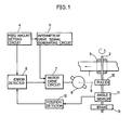
- Fig. 1 is a block diagram of an example of an intermittent drive control portion in a conventional intermittent drive type magnetic recording apparatus.
- a magnetic tape 1 is held between a capstan shaft 2 and a pinch roller 3 so that it is moved at a certain speed by the rotation of the capstan shaft 2.
- a feed amount setting circuit 4 is adapted to set an intermittent feed amount of the magnetic tape 1, so that a feed amount setting signal is generated therefrom.
- the feed amount setting signal is provided as a signal including a prescribed number of pulses (10 pulses, for example) representing a power running period and a prescribed number of pulses (6 pulses, for example) representing a braking period.
- the feed amount setting signal is supplied to an intermittent drive signal generating circuit 5 and to one input of an error detector 6.
- the intermittent drive signal generating circuit 5 Based on the feed amount setting signal, the intermittent drive signal generating circuit 5 generates sequentially a run command signal and a brake command signal for intermittently running the magnetic tape 1.
- the output of the intermittent drive signal generating circuit 5 is supplied to a motor drive circuit 7.
- the motor circuit 7 comprises an amplifier etc. and generates sequentially a driving voltage and a braking voltage based on the command signals from the intermittent drive signal generating circuit 5.
- An output of the motor drive circuit 7 is applied to a capstan motor 8.
- the capstan motor 8 has a rotating shaft connected to a pulley 10 through a belt 9.
- the pulley 10 is fixed to the outer circumference of the capstan shaft 2.
- an angle sensor 11 is fixed to the capstan shaft 2.
- the angle sensor 11 generates an angle signal-corresponding to the rotating angle (the rotating distance) of the capstan shaft 2.
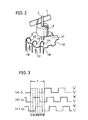
- the angle sensor 11 the technique described in Japanese Patent Laid-Open Gazette No. 122909/1984, for example, may be adopted.
- the angle sensor described in this gazette comprises a fly wheel 111 attached to the capstan shaft 2 as shown in Fig. 2. - Along the outer circumference of the fly wheel 111, a plurality of notches 112 each having a fixed width are provided at equal intervals.
- the three angle signals C 1 , C 2 and C 3 thus obtained undergo logical operation, whereby the angle range corresponding to a cycle T shown in Fig. 3 can be detected by dividing the angle range into six regions I to VI.
- detection of a rotational face can be detected with high precision.
- the three angle signals C 1 , C 2 and C 3 provided from the angle sensor 11 are supplied to a position detector 12.
- the position detector 12 comprises a matrix circuit for applying logical operation to the output of the angle sensor 11.
- the position detector 12 detects a moving amount of the magnetic tape 1 and provides a position signal.
- the position signal is provided as a pulse signal having pulses the number of which corresponds to the moving amount of the magnetic tape 1.
- the output of the position detector 12 is supplied to the other input of the error detector 6.
- the error detector 6 comprises a counter and a comparator etc.
- the error signal is supplied to the motor drive circuit 7 as a correction signal.
- the capstan shaft 2 comprises a brake 13 for braking the rotating movement of the capstan shaft 2.
- a brake 13 a mechanical brake with a felt pad attached thereto is generally adopted.
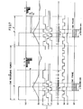
- Fig. 4 is a waveform diagram for explaining the operation of the conventional example shown in Fig. 1.
- Fig. 4(a) represents the output voltage of the motor drive circuit 7, namely, the voltage applied to the capstan motor 8;
- Fig. 4(b) represents the running speed of the magnetic tape 1;
- Fig. 4(c) represents the angle signals provided from the angle sensor 11;
- Fig. 4(d) represents the position signal obtained from the position detector 11.
- Fig. 4(e) represents pulses generated from a rotational drum pulse generator (not shown) (generally called FF pulses, which serve as reference pulses for adjusting the face of the rotational drum);
- Fig. 4(f) represents a video head writing pulse; and
- Fig. 4(e) represents an FM video signal written in the magnetic tape 1.
- this apparatus controls intermittent drive operation based on the feed amount setting signal provided from the feed amount setting circuit 4. More specifically, from the feed amount setting circuit 4, 16 pulses for example are generated, the first to the tenth pulses commanding a power running operation and the eleventh to the sixteenth pulses commanding a braking operation.
- the intermittent drive signal generating circuit 5 makes the motor drive circuit 7 generate a positive drive voltage as shown in Fig. 4(a) in a period corresponding to the first to tenth pulses of the feed amount setting signal so that the positive drive voltage is applied to the capstan motor 8.
- the capstan motor 8 rotates in the forward direction.
- the rotation of the capstan motor 8 is transmitted to the pulley 10 through the belt 9 to rotate the capstan shaft 2 in the forward direction.
- the running speed of the magnetic tape 1 increases gradually as shown in Fig. 4(b).
- the write timing to is determined at a position shown by an arrow in Fig. 4(e) based on the FF pulses shown in Fig. 4(e) and the video head writing pulse shown in Fig. 4(f). In one frame period (l/30sec) after this timing t 0 , the FM video signal is really written by the video head.
- Fig. 4(c) when the capstan shaft 2 rotates, three angle signals C1, C 2 and C 3 as shown in Fig. 4(c) are provided from the angle sensor 11. These angle signals are supplied to the position detector 12 so that they are converted to a position signal indicating the position of the magnetic tape 1. More specifically, the position detector 12 provides a pulse signal as shown in Fig. 4(d), the number of pulses of this pulse signal indicating the moving amount of the capstan shaft 2, that is, the position of the magnetic tape 1.
- the position detector 12 is structured so as to generate pulses equal to the number of pulses of the feed amount setting signal from the feed amount setting circuit 4, that is, 16 pulses, in case where intermittent drive operation is performed in an ideal manner.
- intermittent recording of a FM video signal for one frame is completed.
- This intermittent recording is repeated at intervals of several seconds for example.
- a FM video signal of each frame is recorded at a position adjacent to the FM video signal of the immediately preceding frame and in appearance, signals of the respective frames are continuously recorded on the magnetic tape 1 (see Fig. 5). More specifically, after recording of one frame has been done, the magnetic tape 1 is stopped for several seconds and then the magnetic tape 1 is made to run again to record the subsequent frame.
- intermittent drive is controlled so that a blank or an overlap may not be generated between the adjacent frames.
- the feed amount setting circuit 4 sets a power running period and a braking period for intermittent drive to specified values.
- the rotating angle of the capstan shaft 2, that is, the moving amount of the magnetic tape 1 is, generally, not precisely coincident with the set value because of the moment of inertia of the capstan system.
- the position signal from the position detector 12 unavoidably contains 17 or more pulses. If the subsequent frame is written in this state, a blank is generated between this frame and the preceding frame.
- the error detector 6 compares the feed amount setting signal from the feed amount setting circuit 4 and the position signal from the position detector 12 and determines whether the position signal contains exactly 16 pulses. If the number of pulses of the position signal is other than 16, the error detector 6 applies a correction voltage as shown by the solid line 20 or the dotted line 21 in Fig. 4(a) to the capstan motor 8 through the motor drive circuit 7. More specifically, if the number of pulses of the position signal is larger than 16, a negative voltage (a reverse voltage) as shown by the solid line 20 is applied to the capstan motor 8 and if the number of pulses is smaller than 16, a positive voltage (a forward voltage) as shown by the dotted line 21 is applied thereto. As a result, the capstan motor 8 is made to rotate in the reverse direction or in the forward direction so that correction is made. (In this case, the moving amount is extremely small.)
- intermittent operation can be performed correctly only in the initial state (at the time of delivery of the product from a factory).
- such an apparatus is delivered in a state in which the correction voltage has been adjusted so that recording can be made continuously without causing a blank or an overlap between the adjacent frames.
- a brake 13 is necessarily needed for applying rapid braking to the capstan shaft 2.
- the brake 13 comprises generally a felt pad pressed against the outer surface of a fly wheel as described above.
- the braking force of the brake 13 is changed due to abrasion and the like of the pad as the time passes by. If the braking force of the brake 13 is changed, the magnetic tape 1 is not stopped at a desired position and a position error increases. According to the increase of the position error, the correction amount of the correction voltage 20 or 21 is increased, causing problems as follows.
- the present invention is adapted such that the brake torque of intermittent running means is changed based on an error detected by comparison between the intermittent feed amount of a magnetic recording medium preset by feed amount setting means and the real feed amount of the magnetic recording medium detected by feed amount detecting means.
- the brake torque of the intermittent running means is changed based on an error detected by comparison between the preset feed amount in intermittent drive and the real feed amount, a position error of the magnetic recording medium can always be maintained at a small value.
- the error can be corrected in a short period and the correction of the error can be completed stably in one drive period in intermittent recording. Accordingly, an overlap or a blank between the adjacent frames can be prevented.
- little slack is caused in the magnetic recording medium by the correction of the error and, therefore, unstable operation will never occur.
- the apparatus of the present invention can perform intermittent recording stably for a long period.
- Fig. 6 is a schematic block diagram showing an embodiment of the present invention.
- a feature of this embodiment resides in that a motor drive amount correction signal generating circuit 14 is further provided to increase the reliability in intermittent recording operation, as compared with the conventional apparatus shown in Fig. 1. More specifically, a motor drive amount correction signal generating circuit 14 is connected between an error detector 6 and a motor drive circuit 7.
- the construction of the other portions is the same as in the conventional apparatus shown in Fig. 1. Therefore, the portions corresponding to those shown in Fig. 1 are denoted by the same reference numerals and description thereof will be omitted.
- the above described motor drive amount correction signal generating circuit 14 corrects the error according to an error signal generated from the error detector 6 (namely, it makes a capstan motor 8 to rotate in the forward direction or in the reverse direction) and changes the brake torque of the capstan motor 8 if the error amount is large so that the error-may always be within a permissible range.
- an error signal generated from the error detector 6 namely, it makes a capstan motor 8 to rotate in the forward direction or in the reverse direction
- changes the brake torque of the capstan motor 8 if the error amount is large so that the error-may always be within a permissible range.
- the motor drive amount correction signal generating circuit 14 is designed to have a function of providing forward rotation pulses and reverse rotation pulses by changing successively the polarity of the pulses, the number of pulses and a pulse amplitude value according to the error signal from the error detector 6 and a function of changing the braking voltage generated by the motor drive circuit 7.
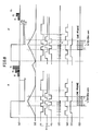
- Figs. 7 and 8 are waveform diagrams for explaining the operation of the embodiment shown in Fig. 6.
- Fig. 7 shows the operation in the case in which the load of the capstan shaft 2 is decreased, for example, in the case in which the brake 13 works loosely.
- Fig. 8 shows the operation in the case in which the load of the capstan shaft 2 is increased, for example, the case in which the brake 13 works tightly.
- Figs. 7(a) to 7(g) and Figs. 8(a) to 8(g) show the waveforms of the same signals as in Figs. 4(a) to 4(g).
- the magnetic tape 1 does not stop at a desired position and overruns.
- the position signal provided from the position detector 12 unavoidably contains 17 or more pulses as shown in Fig. 7(d) (the desired number of pulses being 16).
- the error detector 6 detects an excess in the number of pulses of the position signal from the position detector 12 and the number exceeding the desired number of pulses and provides the detection output to the motor drive amount correction signal generating circuit 14.
- the motor drive amount correction signal generating circuit 14 generates small reverse rotation pulse groups t l , t 2' t 3 , etc.
- the overrun can be corrected only by using the above stated small reverse rotation pulse groups t l , t 2 , t 3 , etc.
- the brake 13 works more loosely, the number of pulses of the position signal generated in one frame recording period P exceeds the desired number 16 by 3 pulses or more (for example, 19 pulses are generated as in the position signal (d) in the period A shown in Fig. 7).
- the overrun can not be corrected only by the small reverse rotation pulse groups and in view of the intermittent cycle, those reverse rotation pulse groups t 1 , t 2 , t 3 , etc. can not be generated continuously for a long period.
- control is made to change the braking voltage in the subsequent drive period (as shown by q2, q3, etc.) so that the difference of the number of pulses of the position signal from the desired number 16 may be 2 pulses or less. Within this range of 2 pulses or less, fine correction operation by the reverse rotation pulse groups t l , t 2 , etc. is repeated.
- the motor drive amount correction signal generating circuit 14 changes the levels values) of the reverse rotation pulse groups t 3 , etc.
- the position error -s large correction is made to a large extent by changing the braking voltage in the subsequent drive period and then, fine correction is made in the subsequent drive period.
- the motor drive amount correction signal generating circuit 14 is designed so that the amplitude values of the reverse rotation pulse groups, the number of pulses of each group, the number of steps and the changing range of the braking voltage may be suitable values according to the characteristics and specifications of the apparatus. However, too complicated variations may not be applied to the design if only a material changing little according to the passage of the time is selected as the material of the brake pad.
- fine correction is made by using forward rotation pulse groups t 1 ', t 2 ', t 3 ', etc. (the polarity thereof being opposite to that of the reverse rotation pulse groups t 1 , t 2 , etc.) and if the error largely deviates from the region where fine correction can be applied (for example, the number of pulses of the position signal being 13 or less), the braking voltage in the subsequent drive period is decreased to q2', q3', etc. according to the number of pulses.
- the rotation amount of the capstan shaft 2 hardly changes and normal intermittent tape feeding operation is performed stably even if the state of the brake 13 or the load of the bearing or the like of the capstan shaft 2 is largely changed due to the change according to the passage of the time, or due to the temperature or the humidity. Accordingly; no blank nor overlap is generated after the end of the recording of one frame and the subsequent frame can be recorded continuously without causing any blank or overlap.
- intermittent recording operation is performed stably and intermittent video data is recorded on the magnetic tape 1 in the same format (see Fig. 5) as in the case of continuous recording.
- the motor drive amount correction signal generating circuit 14 is preferably formed by a microcomputer (of approximately 4 bits, for example).
- Fig. 9 is an operation flow chart in the case in which the motor drive amount correction signal generating circuit 14 is formed by a microcomputer. In the following, the operation shown in Fig. 9 will be briefly described.
- the edge of the FF pulses is detected and a time delay is applied (in steps Sl and S2).
- the capstan motor 8 is rotated in the forward direction in the power running period set by the feed amount setting circuit 4 (in steps S3 and-S4).
- the braking weight of the braking voltage to be applied to the capstan motor 8 is set to an initial value ql (in step S5).
- step S8 the braking voltage is applied to the capstan motor 8 and the application of this braking voltage is continued till the capstan motor 8 rotates in the reverse direction (in steps S6 and S7).
- the capstan motor 8 rotates in the reverse direction, mechanical braking by the brake 13 is applied (in step S8).
- step S9 it is determined whether the number of pulses of the position signal generated in one frame recording period P is coincident with the desired number 16 (in step S9). If the coincidence is determined, the program returns to the main routine (not shown) for controlling the whole operation of the VTR. On the other hand, if there is no coincidence, it is determined whether the difference from the desired number of pulses is within a permissible range (for example, 2 pulses or less) (in step S10).
- a permissible range for example, 2 pulses or less
- step Sll it is determined whether the error detected as the difference in the number of pulses is the error on the positive side (the detected number of pulses being larger than the desired number of pulses) or the error on the negative side (the detected number of pulses being smaller than the desired number of pulses) (instep Sll).
- the error on the positive side reverse rotation pulse groups are applied to the motor drive circuit 7 because the magnetic tape 1 has overrun (in step S12). Accordingly, the capstan motor 8 rotates in the reverse direction so that the magnetic tape 1 is moved toward the backward direction.
- step S18 it is determined whether the error is the error on the positive side or the error on the negative side (in step S18).
- the program proceeds to step S19, where the braking weight is incremented by one to increase the braking voltage generated from the motor drive circuit 7 in the subsequent drive period (as shown by q2, q3, etc.).
- the program proceeds to step S20, where the braking weight is decremented by one to decrease the braking voltage generated from the motor drive circuit 7 in the subsequent drive period (as shown by q2', q3', etc.).
- the program then proceeds to the correction routine using reverse rotation pulse groups or forward rotation pulse groups and thus, the position of the magnetic tape 1 is corrected in the same manner as described above.
- a magnetic tape was used as an example of a magnetic recording medium
- a magnetic disc or a magnetic drum may be used as the magnetic recording medium.
Landscapes
- Engineering & Computer Science (AREA)
- Signal Processing (AREA)
- Control Of Electric Motors In General (AREA)
- Stopping Of Electric Motors (AREA)
Applications Claiming Priority (2)
| Application Number | Priority Date | Filing Date | Title |
|---|---|---|---|
| JP39602/85 | 1985-02-26 | ||
| JP60039602A JPH0667270B2 (ja) | 1985-02-26 | 1985-02-26 | 間欠駆動形磁気記録装置 |
Publications (3)
| Publication Number | Publication Date |
|---|---|
| EP0194099A2 true EP0194099A2 (fr) | 1986-09-10 |
| EP0194099A3 EP0194099A3 (en) | 1988-01-13 |
| EP0194099B1 EP0194099B1 (fr) | 1991-05-15 |
Family
ID=12557658
Family Applications (1)
| Application Number | Title | Priority Date | Filing Date |
|---|---|---|---|
| EP86301396A Expired - Lifetime EP0194099B1 (fr) | 1985-02-26 | 1986-02-26 | Appareil d'enregistrement magnétique du type à entraînement intermittent |
Country Status (4)
| Country | Link |
|---|---|
| US (1) | US4723180A (fr) |
| EP (1) | EP0194099B1 (fr) |
| JP (1) | JPH0667270B2 (fr) |
| DE (1) | DE3679218D1 (fr) |
Cited By (3)
| Publication number | Priority date | Publication date | Assignee | Title |
|---|---|---|---|---|
| EP0249382A3 (en) * | 1986-06-10 | 1988-10-05 | Sony Corporation | Apparatus for reproducing video signals as slow-motion pictures |
| EP0275928B1 (fr) * | 1987-01-17 | 1994-06-08 | Sony Corporation | Dispositif de chargement de bande |
| WO1997040492A1 (fr) * | 1996-04-23 | 1997-10-30 | Philips Electronics N.V. | Systeme pour l'enregistrement segment par segment des signaux d'informations sur une bande magnetique entrainable par intermittence |
Families Citing this family (3)
| Publication number | Priority date | Publication date | Assignee | Title |
|---|---|---|---|---|
| JPH02312280A (ja) * | 1989-05-26 | 1990-12-27 | Mitsubishi Electric Corp | 絶縁ゲート型バイポーラトランジスタ |
| JP3039681B2 (ja) * | 1990-11-20 | 2000-05-08 | キヤノン株式会社 | ビデオ信号記録装置 |
| JPH052799A (ja) * | 1991-06-25 | 1993-01-08 | Canon Inc | 回転ヘツド型記録又は再生装置 |
Family Cites Families (10)
| Publication number | Priority date | Publication date | Assignee | Title |
|---|---|---|---|---|
| FR1459370A (fr) * | 1964-10-26 | 1966-04-29 | Ampex | Perfectionnements aux dispositifs d'excitation contrôlée de moteurs |
| US3969663A (en) * | 1974-10-17 | 1976-07-13 | Storage Technology Corporation | Capstan control for a tape drive system |
| JPS5255611A (en) * | 1975-10-31 | 1977-05-07 | Matsushita Electric Ind Co Ltd | Magnetic recording and playback apparatus |
| JPS5667412A (en) * | 1979-11-05 | 1981-06-06 | Sony Corp | Stationary servo-device |
| JPS56140541A (en) * | 1980-04-02 | 1981-11-02 | Matsushita Electric Ind Co Ltd | Magnetic tape driving device |
| US4531166A (en) * | 1981-03-16 | 1985-07-23 | Storage Technology Corporation | Magnetic tape drive with adaptive servo |
| JPS5854886A (ja) * | 1981-09-25 | 1983-03-31 | Sony Corp | 映像信号再生装置 |
| JPS5854885A (ja) * | 1981-09-25 | 1983-03-31 | Sony Corp | 映像信号再生装置 |
| JPS59124055A (ja) * | 1982-12-29 | 1984-07-18 | Mitsubishi Electric Corp | 磁気録画再生装置 |
| JPS60201563A (ja) * | 1984-03-23 | 1985-10-12 | Mitsubishi Electric Corp | キヤプスタンモ−タトルク制御装置 |
-
1985
- 1985-02-26 JP JP60039602A patent/JPH0667270B2/ja not_active Expired - Fee Related
-
1986
- 1986-02-19 US US06/834,555 patent/US4723180A/en not_active Expired - Lifetime
- 1986-02-26 EP EP86301396A patent/EP0194099B1/fr not_active Expired - Lifetime
- 1986-02-26 DE DE8686301396T patent/DE3679218D1/de not_active Expired - Lifetime
Cited By (4)
| Publication number | Priority date | Publication date | Assignee | Title |
|---|---|---|---|---|
| EP0249382A3 (en) * | 1986-06-10 | 1988-10-05 | Sony Corporation | Apparatus for reproducing video signals as slow-motion pictures |
| US4853809A (en) * | 1986-06-10 | 1989-08-01 | Sony Corp. | Apparatus for reproducing video signals as slow-motion pictures |
| EP0275928B1 (fr) * | 1987-01-17 | 1994-06-08 | Sony Corporation | Dispositif de chargement de bande |
| WO1997040492A1 (fr) * | 1996-04-23 | 1997-10-30 | Philips Electronics N.V. | Systeme pour l'enregistrement segment par segment des signaux d'informations sur une bande magnetique entrainable par intermittence |
Also Published As
| Publication number | Publication date |
|---|---|
| DE3679218D1 (de) | 1991-06-20 |
| EP0194099B1 (fr) | 1991-05-15 |
| US4723180A (en) | 1988-02-02 |
| JPH0667270B2 (ja) | 1994-08-24 |
| JPS61196781A (ja) | 1986-08-30 |
| EP0194099A3 (en) | 1988-01-13 |
Similar Documents
| Publication | Publication Date | Title |
|---|---|---|
| US5039027A (en) | Method for control of tape tension between the reels and apparatus therefor | |
| US4157488A (en) | Apparatus and method for controlling a tape drive to maintain a substantially constant linear tape velocity | |
| JPS615462A (ja) | ストツプロツク方式 | |
| EP0194099B1 (fr) | Appareil d'enregistrement magnétique du type à entraînement intermittent | |
| US4442985A (en) | Apparatus for controlling a web transport system | |
| JPH0120502B2 (fr) | ||
| US5464167A (en) | Method and apparatus for the jam-free starting of tape transportation | |
| US3943565A (en) | Track scan initiation and cutout arrangement for a helical scan video recorder | |
| US4086520A (en) | Speed and phase control system | |
| EP0389293B1 (fr) | Signal R.F. d'asservissement de suivi de piste pour magnétoscope | |
| GB2134283A (en) | Magnetic video recording apparatus for intermittent recording | |
| US5209422A (en) | Tape tension and braking control device and method | |
| US5909335A (en) | Tape drive start up and stop tape speed control | |
| EP0849730B1 (fr) | Commande adaptative de transport de bande pour magnétoscope | |
| US5626304A (en) | Apparatus for controlling tape tension | |
| US6364234B1 (en) | Tape loop/slack prevention method and apparatus for tape drive | |
| JP2633967B2 (ja) | リール間テープ張力制御方法 | |
| JPH0668861B2 (ja) | 再生装置 | |
| JPH0732635B2 (ja) | 間欠駆動形磁気記録再生装置 | |
| JP2500385Y2 (ja) | リ−ルサ−ボ装置 | |
| US6204986B1 (en) | Drum motor controller using microcomputer for intermittent slow VTR | |
| JP2626039B2 (ja) | 磁気記録再生装置 | |
| JPH0441423B2 (fr) | ||
| KR100196856B1 (ko) | 비데오 카세트 레코더에서의 슬로우 모드시 엔벨로프 값판정방법 | |
| JPS58179954A (ja) | テ−プ巻取り装置 |
Legal Events
| Date | Code | Title | Description |
|---|---|---|---|
| PUAI | Public reference made under article 153(3) epc to a published international application that has entered the european phase |
Free format text: ORIGINAL CODE: 0009012 |
|
| AK | Designated contracting states |
Kind code of ref document: A2 Designated state(s): DE FR GB |
|
| PUAL | Search report despatched |
Free format text: ORIGINAL CODE: 0009013 |
|
| AK | Designated contracting states |
Kind code of ref document: A3 Designated state(s): DE FR GB |
|
| 17P | Request for examination filed |
Effective date: 19880513 |
|
| 17Q | First examination report despatched |
Effective date: 19891218 |
|
| GRAA | (expected) grant |
Free format text: ORIGINAL CODE: 0009210 |
|
| AK | Designated contracting states |
Kind code of ref document: B1 Designated state(s): DE FR GB |
|
| REF | Corresponds to: |
Ref document number: 3679218 Country of ref document: DE Date of ref document: 19910620 |
|
| ET | Fr: translation filed | ||
| PLBE | No opposition filed within time limit |
Free format text: ORIGINAL CODE: 0009261 |
|
| STAA | Information on the status of an ep patent application or granted ep patent |
Free format text: STATUS: NO OPPOSITION FILED WITHIN TIME LIMIT |
|
| 26N | No opposition filed | ||
| REG | Reference to a national code |
Ref country code: GB Ref legal event code: 746 Effective date: 20010103 |
|
| PGFP | Annual fee paid to national office [announced via postgrant information from national office to epo] |
Ref country code: FR Payment date: 20010213 Year of fee payment: 16 |
|
| PGFP | Annual fee paid to national office [announced via postgrant information from national office to epo] |
Ref country code: GB Payment date: 20010221 Year of fee payment: 16 Ref country code: DE Payment date: 20010221 Year of fee payment: 16 |
|
| REG | Reference to a national code |
Ref country code: FR Ref legal event code: D6 |
|
| REG | Reference to a national code |
Ref country code: GB Ref legal event code: IF02 |
|
| PG25 | Lapsed in a contracting state [announced via postgrant information from national office to epo] |
Ref country code: GB Free format text: LAPSE BECAUSE OF NON-PAYMENT OF DUE FEES Effective date: 20020226 |
|
| PG25 | Lapsed in a contracting state [announced via postgrant information from national office to epo] |
Ref country code: DE Free format text: LAPSE BECAUSE OF NON-PAYMENT OF DUE FEES Effective date: 20020903 |
|
| GBPC | Gb: european patent ceased through non-payment of renewal fee |
Effective date: 20020226 |
|
| PG25 | Lapsed in a contracting state [announced via postgrant information from national office to epo] |
Ref country code: FR Free format text: LAPSE BECAUSE OF NON-PAYMENT OF DUE FEES Effective date: 20021031 |
|
| REG | Reference to a national code |
Ref country code: FR Ref legal event code: ST |