EP0194184B1 - Kreuzkupplungsgabel - Google Patents
Kreuzkupplungsgabel Download PDFInfo
- Publication number
- EP0194184B1 EP0194184B1 EP86400331A EP86400331A EP0194184B1 EP 0194184 B1 EP0194184 B1 EP 0194184B1 EP 86400331 A EP86400331 A EP 86400331A EP 86400331 A EP86400331 A EP 86400331A EP 0194184 B1 EP0194184 B1 EP 0194184B1
- Authority
- EP
- European Patent Office
- Prior art keywords
- universal joint
- yoke
- base portion
- portions
- ear
- Prior art date
- Legal status (The legal status is an assumption and is not a legal conclusion. Google has not performed a legal analysis and makes no representation as to the accuracy of the status listed.)
- Expired
Links
Images


Classifications
-
- F—MECHANICAL ENGINEERING; LIGHTING; HEATING; WEAPONS; BLASTING
- F16—ENGINEERING ELEMENTS AND UNITS; GENERAL MEASURES FOR PRODUCING AND MAINTAINING EFFECTIVE FUNCTIONING OF MACHINES OR INSTALLATIONS; THERMAL INSULATION IN GENERAL
- F16D—COUPLINGS FOR TRANSMITTING ROTATION; CLUTCHES; BRAKES
- F16D3/00—Yielding couplings, i.e. with means permitting movement between the connected parts during the drive
- F16D3/16—Universal joints in which flexibility is produced by means of pivots or sliding or rolling connecting parts
- F16D3/26—Hooke's joints or other joints with an equivalent intermediate member to which each coupling part is pivotally or slidably connected
-
- F—MECHANICAL ENGINEERING; LIGHTING; HEATING; WEAPONS; BLASTING
- F16—ENGINEERING ELEMENTS AND UNITS; GENERAL MEASURES FOR PRODUCING AND MAINTAINING EFFECTIVE FUNCTIONING OF MACHINES OR INSTALLATIONS; THERMAL INSULATION IN GENERAL
- F16D—COUPLINGS FOR TRANSMITTING ROTATION; CLUTCHES; BRAKES
- F16D3/00—Yielding couplings, i.e. with means permitting movement between the connected parts during the drive
- F16D3/16—Universal joints in which flexibility is produced by means of pivots or sliding or rolling connecting parts
- F16D3/26—Hooke's joints or other joints with an equivalent intermediate member to which each coupling part is pivotally or slidably connected
- F16D3/38—Hooke's joints or other joints with an equivalent intermediate member to which each coupling part is pivotally or slidably connected with a single intermediate member with trunnions or bearings arranged on two axes perpendicular to one another
- F16D3/40—Hooke's joints or other joints with an equivalent intermediate member to which each coupling part is pivotally or slidably connected with a single intermediate member with trunnions or bearings arranged on two axes perpendicular to one another with intermediate member provided with two pairs of outwardly-directed trunnions on intersecting axes
Definitions
- the present invention relates generally to a universal joint yoke having a higher stiffness and greater joint angle and which is produced by folding a sheet metal blank.
- the present invention relates more specifically to the above-described universal joint yoke for a steering system including two ear portions which are provided with bores for mounting bearings of two trunnions of a cross member and which are interconnected to a base portion provided with other bores through which means for securing the yoke to shock absorbing means, e.g., a rubber coupling is inserted.
- Such a kind of universal joint yoke has been used as one of components constituting a steering column of a steering system applied to automotive vehicles.
- Figs. 1 and 2 show a conventional universal joint yoke.
- a lower joint 3 joints a steering column 1 to a steering gear unit 2.
- Two yokes 5, 6 are attached respectively to upper and lower ends of a lower shaft 4 and two yokes 8, 9 are respectively attached to one end of the steering column 1 and to one end of a gear shaft 7.
- the respective ends of yokes 8, 9 adjoin the opposing yokes 5, 6.
- Each pair of yokes 5, 8 and 6, 9 is universally jointed together by means of respective trunnions 10a, 10b.
- the lower joint 3 has a shock absorbing construction in order to damp vibrations and noises caused by an engine mounted on the vehicle, uneven road surfaces, etc., and transmitted from the steering system located below the lower joint 3 to a steering wheel via a steering shaft 1.
- An essentially disc-shaped rubber coupling 11 is attached to the base portion of the yoke 5 as shock absorbing means by means of bolts and nuts 12, 13 and to the lower shaft 4 (to be described later). Therefore, most of the above-described vibrations and noises transmitted to the lower joint 3 are damped by means of the rubber coupling 11, so that such vibrations and noises cannot be transmitted to the steering wheel and vehicle compartment.
- Japanese Utility Model Application Unexamined Open No. Sho. 57-172,930 (corresponding to U.S. Patent No. 3,901,048 issued on August 26, 1975) exemplifies the universal joint yoke in which the yoke is fixed to the lower joint 3.
- the yoke 5 is made of an essentially diamond-shaped metal plate with both ends of a longer diagonal folded upward to form the shape of a letter "C" in section.
- the yoke 5 comprises: (a) the base portion 15 having holes 14a, 14b for attaching the whole yoke 5 to the rubber coupling 11 and (b) the two ear portions 17a, 17b having two opposing holes 16a, 16b for mounting bearings of two trunnions 10a of the cross member. It is noted that the two opposing holes serve to journal the trunnion 10a.
- the yoke 5 formed as described above is fixed to the upper end of the lower shaft 4 via the rubber coupling 11, as shown in Fig. 2.
- the rubber coupling 11 is fixed to both extended ends of mounting flanges 18a, 18b of a yoke 18 which is attached around an intermediate periphery of the lower shaft 4, the mounting flanges thereof being extended outwardly at a given angle with respect to an axial direction of the lower shaft 4.
- the yoke 5 is fastened to the rubber coupling 11 in such a way that a lower surface of the base portion 5 rests on an upper surface of the rubber coupling 11.
- Bolts 19 are inserted through the holes 14a, 14b shown in Fig. 3 and fastened to the rubber coupling 11 together with corresponding nuts as shown in Fig. 2.
- the two bolts 12 are aligned on the larger diagonal of the yoke, i.e., diamond-shaped sheet metal and that the nuts 13 engaged on threaded portions of both bolts 12 are placed outside of the ear portions 17a, 17b which face each other. It is also noted that a line connecting both bolts 19 is orthogonal to the line connecting both bolts 12.
- the yoke 5 thus fixed to the lower shaft 4 via the rubber coupling 11 is then universally jointed to the opposing yoke 8 fixed to the steering shaft 1 via the trunnion 10a.
- the conventional yoke 5 is formed merely by folding the essentially diamond-shaped metal plate along parallel fold lines to define the base 15 and two ear portions 17a, 17b, the stiffness in the region of fold lines of the two ear portions 17a, 17b is so low that, when the yoke 5 is incorporated in the universal joint of the steering column and a high steering torque is subjected to the yoke 5, the ear portions 17a, 17b tend to deform outwardly.
- This US patent describes a universal joint yoke which a bent sheet metal blank and, comprises a central portion defining a base portion and a pair of ear portions which have two bores for mounting two trunnions of a universal joint cross member, the base portion interconnecting the pair of ear portions and inwardly projecting rib portions.
- An inwardly projecting rib portion is formed along the direction of major axis of each ear portion so as to extend over each ear portion respectively.
- Jt is another object of the present invention to provide a universal joint yoke in which a small rotation radius of the universal joint is achieved.
- each rib is formed symmetrically along said major axis of each ear portion and has dimensions increasing from the bores to the base portion and decreasing from the middle ridge to the edges of said ear portions, so that the rear surface of each rib realizes a corresponding recess on the outer side of each ear portion.
- Fig. 5 through 8 show a first preferred embodiment of a universal joint yoke according to the present invention.
- a preliminarily shaped sheet metal of a predetermined profile is pressed to form a yoke 21 having a cross section substantially of a letter "C" shape shown in Fig. 5.
- the sheet metal 22 shown in Fig. 6 comprises: a circular base portion 23; and two ear portions 24a, 24b of substantially equal width W to each other and with central rib portions inwardly projecting from their bottom ends toward a center of the circular base 23.
- the predetermined profile of the preliminarily shaped sheet metal 22 refers to a substantially cruciate form as denoted by a phantom line and a solid line continued to the phantom line in Fig. 6.
- the preliminarily shaped sheet metal before pressing has such a profile that small elliptical extensions are interconnected to a central portion having circuit peripheries at ends of the minor axis of each elliptical extension.
- the above-described metal sheet 22 is formed by a press using, e.g., a yoke forming apparatus 27 comprising a lower die 27a and upper punch 27b as shown in Fig. 7.
- the metal sheet 22 is bent to form the two ear portions 24a, 24b along preselected lines 26a, 26b until they stand substantially perpendicular to the base portion 28 and in parallel to each other.
- the yoke 21 thus finished comprises the circular base portion 28 truncated along diametrically opposing secants 26a, 26b denoted by a dot-and- dash line in Fig. 6 and the two ear portions 30a, 30b which extend substantially upwardly from the base portion 28 with their peripheral edges being formed with curvatures 29.
- the curvatures 29 comprise convex portions 29a adjacent to the base portion 28 and concave portions 29b adjacent to the convex portions 29a.
- the concave portions 29b smoothly join distal ends of the two ear portions 30a, 30b, as shown in Figs. 5 and 8.
- projections 31a, 31b and matching recesses 32a, 32b are provided respectively on either side of the lower die 27a and on the corresponding sides of the upper punch 27b in the forming apparatus shown in Fig. 7. It should be noted that, as shown in Figs. 5 and 8, the metal sheet 22 is embossed to form recesses 34a, 34b directing toward the center of the base portion 23 and thereby inwardly projecting ribs are correspondingly formed above the respective recesses.
- the ribs 33a, 33b are formed at respective central portions bridging each of two ear portions 30a, 30b and the base portion in order to prevent a springback action after press forming of the two ear portions 30a, 30b and to increase the stiffness of the ear portions. Therefore, exposed threaded portions of bolts and nuts for fastening a rubber coupling 35 to a mounting flange to be described later are nestled into these recesses 34a, 34b of the universal joint yoke 21. Furthermore, two holes 36a, 36b for attaching the yoke 21 to the rubber coupling 35 are bored through a flat surface of the base portion 28 and two holes 37a, 37b are bored through the upper ends of the two ear portions 30a, 30b, respectively.
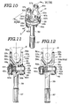
- the yoke 21 shown in Fig. 5 will be described with reference to Figs. 9 through 11 which is used in the universal joint between the steering column 1 and lower joint 3.
- the rubber coupling 35 in the first embodiment has a shape of a disc having substantially the same diameter as a maximum diameter of the base portion 28 of the yoke 21.
- the rubber coupling 35 has an internal fabric reinforcement structure and has four holes 38a, 38b, 38c, and 38d disposed radially symmetrically about a center of the disc.
- One pair of diametrically opposed holes 38a, 38c are provided internally with metal bushes 41a, 41c projecting toward a lower shaft 39 for accommodating bolts 40a, 40c and, on the other hand, another pair of holes 38b, 38d are also provided internally with metal bushes 41b, 41d projecting toward the yoke 21 for accommodating bolts 40b, 40d.
- plastic collars 42a, 42c, 42b, and 42d are externally mounted around projected peripheries of the respective bushes 41a, 41c, 41b, and 41d and two H-shaped stopper plates 43a, 43b are fastened to both upper and lower surfaces of the rubber coupling 5 by means of bolts and nuts 40a, 49a, 40c, 49c, 40b, 40d, 49d, and 49b, respectively, at positions substantially offset 90 degrees with respect to each other.
- Each sidewall of cut-out recesses of the stopper plates 43a, 43b will be contacted with adjacently located plastic collars 42a, 42c, 42b and 42d when the universal joint is subjected to a large torque from the steering column. Thereby, the rubber coupling 35 is protected against an excessive twisting and damage due to the large torque.
- the mounting flange 46 is formed integrally at one end of the lower shaft 39 and a serration 47 is formed at the other end of the lower shaft 39.
- the bolts 40a, 40c are passed through the holes 38a, 38c of the rubber coupling 35, and corresponding holes 44a, 44c of the one stopper plate 43b disposed on the upper surface of the rubber coupling 35 via the plastic collars 42a, 42c.
- the nuts 49a, 49c are, in turn, turned inwardly around corresponding threaded parts of the bolts 40a, 40c so as to fasten the rubber coupling 35 to the mounting flange 46. In this way, the rubber coupling 35 can appropriately be mounted on the mounting flange 46 of the lower shaft 39.
- the yoke 21 is mounted on the upper surface of the rubber coupling 35 in the following way.
- the bolts 40b, 40d for fastening the yoke 21 to the rubber coupling 35 are passed through the corresponding holes 36a, 36b from above the upper flat surface of the base portion 28.
- the bolts 40b, 40d are then passed through the holes 38b, 38d of the rubber coupling 35 and holes 44a, 44b of the other stopper plate 43b resting on the lower surface. of the rubber coupling 35 via the respective plastic collars 42b, 42d.
- fastening means comprising rivet pins 50a, 50b, 50c, and 50d may alternatively be used in place of fastening means comprising the bolt-and-nut arrangement in order to mount the yoke 21 on the rubber coupling 35 and to mount the rubber coupling 35 on the lower shaft 39.
- the circular periphery of the base portion 28 of the yoke 21 is aligned with the circular periphery of the rubber coupling 35 and the outer diameter of the base portion 28 can substantially be the same as that of the rubber coupling 35, no part of the periphery of the base portion 28 is projected out of the circumference of the rubber coupling 35.
- the yoke 21 is formed by pressing the sheet metal 22 of the substantially cruciate form shown in Fig. 6 in such a way that the sheet metal 22 is folded along the diametrically opposed secants 26a, 26b of the circle constituting the base portion 23 to form the two ear portions 30a, 30b and is at the same time embossed to form a reinforcing rib bridging each of the two ear portions and the base portion as shown in Fig. 6, a larger joint angle with respect to the opposite yoke 8 and a higher stiffness of the ear portions are obtained as compared with the conventional universal joint yoke shown in Figs. 2 through 4.
- the opposite yoke 8 is free to swing through a larger joint angle with respect to the trunnions 10a as compared with the conventional universal joint yoke.
- the ends of bolts 40a, 40c and nuts 49a, 49c are nestled in the recesses 34a, 34b of the yoke 21, the bolts 40a, 40c can lie within a circular outline of the base portion 28 of the yoke 21. Consequently, the base portion 28 can have substantially the same dimensions as those of the rubber coupling 35 so that the rubber coupling 35 having a minimum diameter can be achieved. As a result, a rubber coupling joint with compact design, higher spatial effectiveness around the steering system, and lighter weight can be obtained.
- Figs. 13 through 15 show a second preferred embodiment of the universal joint yoke according to the present invention.
- the yoke 21 is shaped substantially in the letter "C" form in cross section by pressing in the same way as described in the first preferred embodiment.
- the sheet metal 22 comprises two ear portions 24a, 24b and base portion 23 as in the first preferred embodiment.
- Fig. 16 shows contiguous convexities 31 a, 31 b, 31c on the bottom surface and edges of the lower press 27a in a second yoke forming apparatus 27. Accordingly, recesses 32a, 32b, 32c opposing to the respective convexities 31a, 31b, 31c are formed on the upper punch 27b.
- rib 33a, 33b, 33c is contiguously extended from one ear portion 30a to the other ear portion 30b and base portion 23, as shown in Figs. 13 to 15.
- substantially hemispherical cone-shaped recesses 34b, 34c are interconnected via the central recess 34a and are correspondingly formed on the rear surface of the contiguous rib 33a, 33b, and 33c, as shown in Figs. 13,14, and 15. Therefore, in the same way as the first preferred embodiment, bolts 40a, 40c for fastening the rubber coupling 35 to the lower shaft 39 can well be nestled into the recesses 34b, 34c.
- the contiguous rib 33a, 33b, and 33c increases the stiffness of the two ear portions 30a, 30b of the yoke 21 along their width W direction against deformation of the yoke and springback action of the press.formed ear portions.
- the bolts 40a, 40c projected from the nuts 49a, 49c can be nestled into the recesses 34b, 34c of the yoke 21, the bolts 40a, 40c can be disposed on the same circumference of the radius defined by the bolts 40b, 40d. That is to say, the bolts 40a, 40b, 40c, 40d and nuts 49a, 49b, 49c, 49d can be disposed within the periphery of the circular base or the size of the rubber coupling 35.
- the universal joint yoke is constructed as described above, the stiffness of the universal joint yoke can remarkably be increased while allowing its dimensions to be reduced. In addition, since the universal joint yoke and members on which the universal joint yoke is mounted can be minimized, the weight of the whole universal joint can be reduced and more free space can be obtained around the universal joint.
- the rotation radius of the universal joint yoke can be reduced and joint angle of the yoke with respect to the opposite yoke can be increased.
- the universal joint yoke according to the present invention is resistant to deformation under the large torque applied during the operation of steering wheel.
Landscapes
- Engineering & Computer Science (AREA)
- General Engineering & Computer Science (AREA)
- Mechanical Engineering (AREA)
- Steering Controls (AREA)
Claims (14)
Applications Claiming Priority (6)
| Application Number | Priority Date | Filing Date | Title |
|---|---|---|---|
| JP34517/85 | 1985-02-25 | ||
| JP3451885A JPS61197821A (ja) | 1985-02-25 | 1985-02-25 | 自在継手用ヨ−ク |
| JP60034517A JPS61197820A (ja) | 1985-02-25 | 1985-02-25 | 自在継手用ヨ−ク |
| JP34518/85 | 1985-02-25 | ||
| JP111040/85U | 1985-07-22 | ||
| JP1985111040U JPH0325445Y2 (de) | 1985-07-22 | 1985-07-22 |
Publications (2)
| Publication Number | Publication Date |
|---|---|
| EP0194184A1 EP0194184A1 (de) | 1986-09-10 |
| EP0194184B1 true EP0194184B1 (de) | 1989-10-11 |
Family
ID=27288443
Family Applications (1)
| Application Number | Title | Priority Date | Filing Date |
|---|---|---|---|
| EP86400331A Expired EP0194184B1 (de) | 1985-02-25 | 1986-02-18 | Kreuzkupplungsgabel |
Country Status (5)
| Country | Link |
|---|---|
| US (1) | US4702722A (de) |
| EP (1) | EP0194184B1 (de) |
| KR (1) | KR950013929B1 (de) |
| AU (1) | AU571770B2 (de) |
| DE (1) | DE3666274D1 (de) |
Families Citing this family (31)
| Publication number | Priority date | Publication date | Assignee | Title |
|---|---|---|---|---|
| ES2003937A6 (es) * | 1986-11-06 | 1988-12-01 | Daumal Castellon Melchor | Horquilla para articulaciones cardan |
| DE3641956C1 (de) * | 1986-12-09 | 1988-06-01 | Gelenkwellenbau Gmbh | Kreuzgelenk |
| AT392132B (de) * | 1987-11-03 | 1991-01-25 | Steyr Daimler Puch Ag | Verbindung der kurbelwelle einer schalldicht gekapselten brennkraftmaschine mit der koaxialen antriebswelle der ausserhalb der kapsel angeordneten hilfseinrichtungen |
| US4881924A (en) * | 1987-12-07 | 1989-11-21 | Dana Corporation | Yoke for Hookes-type universal joint |
| US5222913A (en) * | 1989-05-30 | 1993-06-29 | Nippon Seiko Kabushiki Kaisha | Resilient connector for steering shaft |
| US5366411A (en) * | 1989-07-13 | 1994-11-22 | Holset Engineering Company, Ltd. | Flexible coupling incorporating elastomeric elements with embedded bushes |
| US5152718A (en) * | 1991-09-03 | 1992-10-06 | General Motors Corporation | Intermediate shaft assembly for steering system |
| FR2688278B1 (fr) * | 1992-03-06 | 1994-11-18 | Nacam | Accouplement elastique. |
| DE9316024U1 (de) * | 1993-10-22 | 1994-06-09 | Ehrenberg, Kurt, Carona | Gelenkhälfte für Kreuzgelenke |
| JP3431732B2 (ja) * | 1995-09-08 | 2003-07-28 | 富士機工株式会社 | ステアリングコラム用軸継手 |
| JP3247605B2 (ja) * | 1996-04-11 | 2002-01-21 | 株式会社山田製作所 | 弾性軸継手装置 |
| DE19634101C2 (de) * | 1996-08-23 | 1998-07-02 | Daimler Benz Ag | Lenkungsanlage für ein Kraftfahrzeug mit einer unteren Lenkspindel |
| US5868626A (en) * | 1997-04-30 | 1999-02-09 | Dana Corporation | Universal joint yoke having axially-extending grooves |
| JP3692733B2 (ja) | 1997-10-09 | 2005-09-07 | 日本精工株式会社 | 自動車用ステアリングジョイント装置 |
| KR100754506B1 (ko) * | 2003-12-10 | 2007-09-03 | 주식회사 만도 | 스윙요크의 유격 방지구조 |
| US7213999B2 (en) * | 2004-01-30 | 2007-05-08 | Torque-Traction Technologies, Llc. | Fastener with opposite hand threads for securing two components together |
| EP1828630A2 (de) * | 2004-10-29 | 2007-09-05 | Ronjo Company | Kardangelenkanordnung für kraftfahrzeugantriebsstrangsystem |
| US8182351B2 (en) | 2004-10-29 | 2012-05-22 | Ronjo Llc | Universal joint assembly for an automotive driveline system |
| FR2904070B1 (fr) * | 2006-07-24 | 2008-09-05 | Peugeot Citroen Automobiles Sa | Joint homocinetique a rotule centrale |
| DE102010041960B4 (de) * | 2010-07-30 | 2012-12-20 | Aktiebolaget Skf | Gelenkanordnung |
| US8939845B2 (en) | 2010-08-27 | 2015-01-27 | Dana Automotive Systems Group, Llc | Tube yoke for a driveshaft assembly |
| US9470270B2 (en) | 2010-08-27 | 2016-10-18 | Dana Automotive Systems Group, Llc | Tube yoke for a driveshaft assembly |
| MX2013006931A (es) * | 2010-12-17 | 2013-12-02 | Ronjo Llc | Ensamble de junta universal para sistema de transmision automotriz. |
| ES2691121T3 (es) * | 2012-12-13 | 2018-11-23 | Vibracoustic North America, L.P. | Amortiguador de eje de transmisión y procedimiento de ensamblaje |
| US10897071B2 (en) * | 2013-01-16 | 2021-01-19 | Haeco Americas, Llc | Universal adapter plate assembly |
| US10752348B2 (en) * | 2014-12-19 | 2020-08-25 | Sikorsky Aircraft Corporation | Adjustable scissor link |
| US10378590B2 (en) * | 2015-09-17 | 2019-08-13 | J. E. Reel Truck Parts, Inc. | Modular driveline yoke |
| CN105416053A (zh) * | 2015-11-30 | 2016-03-23 | 安徽江淮汽车股份有限公司 | 传动轴挠性连接组件及汽车 |
| CN212921686U (zh) * | 2020-04-16 | 2021-04-09 | 赛格威科技有限公司 | 全地形车的转向机构及全地形车 |
| CN116985896A (zh) * | 2023-07-27 | 2023-11-03 | 东风汽车集团股份有限公司 | 一种转向系统、角模块以及车辆 |
| KR20250095873A (ko) * | 2023-12-20 | 2025-06-27 | 남양넥스모 주식회사 | 요크 조인트 및 이를 포함하는 차량용 인텀샤프트 조립체 |
Family Cites Families (10)
| Publication number | Priority date | Publication date | Assignee | Title |
|---|---|---|---|---|
| US2067283A (en) * | 1934-08-01 | 1937-01-12 | Joseph E Padgett | Joint member and method of making same |
| US2208547A (en) * | 1937-09-04 | 1940-07-16 | United Carr Fastener Corp | Universal joint |
| US2264727A (en) * | 1940-03-22 | 1941-12-02 | Fraser Kenneth G | Universal joint |
| US3045455A (en) * | 1961-01-16 | 1962-07-24 | Chain Belt Co | Unviersal joint for shafts |
| DE1990693U (de) * | 1968-05-04 | 1968-08-01 | Porsche Kg | Universalkreuzgelenk. |
| DE2244412C2 (de) * | 1972-09-09 | 1973-12-13 | A. Ehrenreich & Cie, 4000 Duesseldorf-Oberkassel | Kreuzgelenk Gabel aus Blech |
| US3901048A (en) * | 1973-05-10 | 1975-08-26 | Nadella | Universal joint yoke |
| DE2900846C2 (de) * | 1979-01-11 | 1985-03-21 | Kurt 8751 Heimbuchenthal Ehrenberg | Gelenkhälfte für Kreuzgelenke o.dgl. |
| JPS55163536U (de) * | 1979-05-11 | 1980-11-25 | ||
| FR2479375A1 (fr) * | 1980-03-28 | 1981-10-02 | Nadella | Assemblage comportant un organe d'accouplement a moyeu renforce |
-
1986
- 1986-02-17 AU AU53668/86A patent/AU571770B2/en not_active Ceased
- 1986-02-18 DE DE8686400331T patent/DE3666274D1/de not_active Expired
- 1986-02-18 US US06/830,274 patent/US4702722A/en not_active Expired - Lifetime
- 1986-02-18 EP EP86400331A patent/EP0194184B1/de not_active Expired
- 1986-02-24 KR KR1019860001280A patent/KR950013929B1/ko not_active Expired - Lifetime
Also Published As
| Publication number | Publication date |
|---|---|
| AU571770B2 (en) | 1988-04-21 |
| KR950013929B1 (ko) | 1995-11-18 |
| KR860006379A (ko) | 1986-09-09 |
| DE3666274D1 (en) | 1989-11-16 |
| US4702722A (en) | 1987-10-27 |
| AU5366886A (en) | 1986-09-04 |
| EP0194184A1 (de) | 1986-09-10 |
Similar Documents
| Publication | Publication Date | Title |
|---|---|---|
| EP0194184B1 (de) | Kreuzkupplungsgabel | |
| GB2339610A (en) | Universal Joint | |
| JPS6148609A (ja) | ボ−ルジヨイントの製造方法 | |
| US6022047A (en) | Universal joint and a yoke therefor for a steering apparatus | |
| JPH03197273A (ja) | ステアリングホイール | |
| US5222913A (en) | Resilient connector for steering shaft | |
| US5366413A (en) | Elastic universal coupling | |
| US5551919A (en) | Steering column assembly | |
| JPH046587B2 (de) | ||
| GB2299062A (en) | Energy-absorbing shaft structure for a vehicle steering column | |
| US5435785A (en) | Elasting coupling unit especially for a vehicle steering column | |
| US6190259B1 (en) | Steering joint device for a car | |
| JP3661327B2 (ja) | 自在継手用ヨーク | |
| JPS6162621A (ja) | ユニバーサルジヨイント | |
| US4953423A (en) | Steering wheel with shock absorber | |
| JPH02292520A (ja) | 自在継手 | |
| JPH0378490B2 (de) | ||
| US7810407B2 (en) | Fixed type constant velocity joint | |
| JPH0439092Y2 (de) | ||
| JPH0422111Y2 (de) | ||
| JP2001012490A (ja) | 自在継手用ヨーク | |
| JP3389721B2 (ja) | 弾性自在継手 | |
| JP3952172B2 (ja) | ステアリングシャフト用軸継手 | |
| JPH0442215Y2 (de) | ||
| JPH06185535A (ja) | ステアリング装置用等速ジョイント |
Legal Events
| Date | Code | Title | Description |
|---|---|---|---|
| PUAI | Public reference made under article 153(3) epc to a published international application that has entered the european phase |
Free format text: ORIGINAL CODE: 0009012 |
|
| AK | Designated contracting states |
Kind code of ref document: A1 Designated state(s): DE FR GB IT NL SE |
|
| 17P | Request for examination filed |
Effective date: 19870305 |
|
| 17Q | First examination report despatched |
Effective date: 19880505 |
|
| ITF | It: translation for a ep patent filed | ||
| GRAA | (expected) grant |
Free format text: ORIGINAL CODE: 0009210 |
|
| AK | Designated contracting states |
Kind code of ref document: B1 Designated state(s): DE FR GB IT NL SE |
|
| PG25 | Lapsed in a contracting state [announced via postgrant information from national office to epo] |
Ref country code: NL Effective date: 19891011 |
|
| REF | Corresponds to: |
Ref document number: 3666274 Country of ref document: DE Date of ref document: 19891116 |
|
| ET | Fr: translation filed | ||
| NLV1 | Nl: lapsed or annulled due to failure to fulfill the requirements of art. 29p and 29m of the patents act | ||
| PLBE | No opposition filed within time limit |
Free format text: ORIGINAL CODE: 0009261 |
|
| STAA | Information on the status of an ep patent application or granted ep patent |
Free format text: STATUS: NO OPPOSITION FILED WITHIN TIME LIMIT |
|
| 26N | No opposition filed | ||
| ITTA | It: last paid annual fee | ||
| EAL | Se: european patent in force in sweden |
Ref document number: 86400331.4 |
|
| PGFP | Annual fee paid to national office [announced via postgrant information from national office to epo] |
Ref country code: FR Payment date: 20011228 Year of fee payment: 17 |
|
| REG | Reference to a national code |
Ref country code: GB Ref legal event code: IF02 |
|
| PGFP | Annual fee paid to national office [announced via postgrant information from national office to epo] |
Ref country code: SE Payment date: 20020118 Year of fee payment: 17 |
|
| PGFP | Annual fee paid to national office [announced via postgrant information from national office to epo] |
Ref country code: GB Payment date: 20020212 Year of fee payment: 17 |
|
| PGFP | Annual fee paid to national office [announced via postgrant information from national office to epo] |
Ref country code: DE Payment date: 20020213 Year of fee payment: 17 |
|
| PG25 | Lapsed in a contracting state [announced via postgrant information from national office to epo] |
Ref country code: GB Free format text: LAPSE BECAUSE OF NON-PAYMENT OF DUE FEES Effective date: 20030218 |
|
| PG25 | Lapsed in a contracting state [announced via postgrant information from national office to epo] |
Ref country code: SE Free format text: LAPSE BECAUSE OF NON-PAYMENT OF DUE FEES Effective date: 20030219 |
|
| PG25 | Lapsed in a contracting state [announced via postgrant information from national office to epo] |
Ref country code: DE Free format text: LAPSE BECAUSE OF NON-PAYMENT OF DUE FEES Effective date: 20030902 |
|
| EUG | Se: european patent has lapsed | ||
| GBPC | Gb: european patent ceased through non-payment of renewal fee | ||
| PG25 | Lapsed in a contracting state [announced via postgrant information from national office to epo] |
Ref country code: FR Free format text: LAPSE BECAUSE OF NON-PAYMENT OF DUE FEES Effective date: 20031031 |
|
| REG | Reference to a national code |
Ref country code: FR Ref legal event code: ST |
|
| PG25 | Lapsed in a contracting state [announced via postgrant information from national office to epo] |
Ref country code: IT Free format text: LAPSE BECAUSE OF NON-PAYMENT OF DUE FEES;WARNING: LAPSES OF ITALIAN PATENTS WITH EFFECTIVE DATE BEFORE 2007 MAY HAVE OCCURRED AT ANY TIME BEFORE 2007. THE CORRECT EFFECTIVE DATE MAY BE DIFFERENT FROM THE ONE RECORDED. Effective date: 20050218 |