EP0194509B1 - Schlauchbandförderanlage - Google Patents
Schlauchbandförderanlage Download PDFInfo
- Publication number
- EP0194509B1 EP0194509B1 EP86102493A EP86102493A EP0194509B1 EP 0194509 B1 EP0194509 B1 EP 0194509B1 EP 86102493 A EP86102493 A EP 86102493A EP 86102493 A EP86102493 A EP 86102493A EP 0194509 B1 EP0194509 B1 EP 0194509B1
- Authority
- EP
- European Patent Office
- Prior art keywords
- belt
- conveyor
- tubular
- rollers
- roller
- Prior art date
- Legal status (The legal status is an assumption and is not a legal conclusion. Google has not performed a legal analysis and makes no representation as to the accuracy of the status listed.)
- Expired
Links
Images
Classifications
-
- B—PERFORMING OPERATIONS; TRANSPORTING
- B65—CONVEYING; PACKING; STORING; HANDLING THIN OR FILAMENTARY MATERIAL
- B65G—TRANSPORT OR STORAGE DEVICES, e.g. CONVEYORS FOR LOADING OR TIPPING, SHOP CONVEYOR SYSTEMS OR PNEUMATIC TUBE CONVEYORS
- B65G15/00—Conveyors having endless load-conveying surfaces, i.e. belts and like continuous members, to which tractive effort is transmitted by means other than endless driving elements of similar configuration
- B65G15/08—Conveyors having endless load-conveying surfaces, i.e. belts and like continuous members, to which tractive effort is transmitted by means other than endless driving elements of similar configuration the load-carrying surface being formed by a concave or tubular belt, e.g. a belt forming a trough
-
- B—PERFORMING OPERATIONS; TRANSPORTING
- B65—CONVEYING; PACKING; STORING; HANDLING THIN OR FILAMENTARY MATERIAL
- B65G—TRANSPORT OR STORAGE DEVICES, e.g. CONVEYORS FOR LOADING OR TIPPING, SHOP CONVEYOR SYSTEMS OR PNEUMATIC TUBE CONVEYORS
- B65G2201/00—Indexing codes relating to handling devices, e.g. conveyors, characterised by the type of product or load being conveyed or handled
- B65G2201/04—Bulk
Definitions
- the invention relates to a hose conveyor system according to the preamble of claim 1.
- the rigid, equidistant arrangement of the idlers also caused the longitudinal edge of the belt edge that had been folded over during hose formation to often collide with the end face of the next idler on the side. In the long run, this caused damage to this longitudinal belt edge, which necessitated costly repairs or even the replacement of the entire belt.
- a belt conveyor system which has the features specified in the characterizing part of patent claim 1, the support rollers of which are thus arranged in the form of roller garlands known per se, with one roller garland each in the tubular sections of the conveyor system approximately the upper or grips the lower half of the hose band cross-section.
- An upper roller garland is preferably assigned to a lower roller garland, which is opposite it either exactly or with a slight displacement in the longitudinal direction of the belt.
- the end points of the roller garlands are supported on the legs of support frames which are open in a U-shape.
- a further advantageous embodiment of the invention is characterized in that at the upper roller garlands the distance between those two rollers which come to rest on both sides of the longitudinal edge of the folded-over belt edge area is greater than the other roller spacings. This prevents the longitudinal edge of the belt from bumping against the end face of the roll adjacent to it and being damaged in the event of slight fluctuations or twisting of the running hose band.
- This increased roller spacing can in particular be achieved by inserting a connecting link between the two said rollers, which are arranged on both sides of the longitudinal edge of the belt, which is longer than the remaining intermediate rollers of the upper garland, the rollers themselves all having the same dimensions.
- the elongated intermediate member is preferably about twice as long as the other intermediate members.
- the conveyor belt used in the belt conveyor system according to the invention which can be formed into a tubular belt, contains embedded thread-like strength members running in the longitudinal direction of the belt, preferably exclusively in the area of its longitudinal edges, and in particular only to the extent that these longitudinal edges overlap one another in the tubular section sections.
- the drive force introduced by a drive roller - which the belt wraps around in a flat position at the turning point of the conveyor system - is evenly transmitted to the entire belt.
- the limitation of the longitudinal strength members to the longitudinal edges of the belt means that the belt in the tubular sections of the system ensures the elastic stretchability of the hose side walls and the underside of the hose, which is required for smooth passage through right or left curves.
- the conveyor belt only contains embedded in the longitudinal direction continuous strength members 1.3, z. B. in the form of steel wire ropes.
- the middle part of the belt can contain conventional reinforcing inserts, which run in the transverse or diagonal direction and are not shown in the drawing, which serve as puncture protection and increase the load-bearing capacity of the belt.
- roller garlands 3 and 4 are articulated on the legs 5.1 and 5.2 of the support frame 5, and the rollers which are rotatable on their axes are articulated to one another via intermediate members 3.12, 3.23 and 4.12, 4.23, respectively.
- the elongated intermediate member 4.12 ensures that the longitudinal edge 1.21 of the folded belt edge 1.20 also maintains a sufficient distance from the laterally adjacent roller 4.1 even in the event of fluctuations in the belt course, in order to avoid collisions of the belt edge 1.21 with the end face of this roller 4.1 and thus damage to the belt edge.
Landscapes
- Engineering & Computer Science (AREA)
- Mechanical Engineering (AREA)
- Structure Of Belt Conveyors (AREA)
Description
- Die Erfindung betrifft eine Schlauchband-Förderanlage gemäss dem Oberbegriff des Patentanspruchs 1.
- Solche Schlauchband-Förderanlagen sind beispielsweise in der DE-PS 943817, der DE-OS 1934342 und der DE-PS 2944448 beschrieben. Bei den bekannten Anlagen dieser Art hat es sich als nachteilig erwiesen, dass die Trag- und Führungsrollen, an denen sich der Fördergurt abstützte und die den Fördergurt in die Schlauchform führten, starr und in unveränderlicher symmetrischer Verteilung um den Gurtquerschnitt herum angeordnet waren. Infolge dieser starren Rollenanordnung wurde dem Fördergurt ständig ein bestimmter durch die Position der Rollen exakt vorgegebener Schlauchquerschnitt aufgezwungen, und zwar unabhängig von der Form und Verteilung des jeweils transportierten Fördergutes. Insbesondere bei sperrigem Fördergut wurde hierbei das Gurtmaterial stark beansprucht, und es konnte zu Beschädigungen des Gurtes kommen.
- Ein ganz wesentlicher Nachteil der bekannten Schlauchband-Förderanlagen bestand darin, dass die Montage des Fördergurtes ebenso wie Wartungs- und Reparaturarbeiten einen hohen Aufwand erforderten, da der Fördergurt durch die ihn rahmenartig umschliessenden Traggestelle, an denen die Rollen fest montiert waren, nur schwer zugänglich war.
- Die starre, äquidistante Anordnung der Tragrollen bewirkte ausserdem, dass die Längskante des bei der Schlauchbildung übergeschlagenen Gurtrandes häufig mit der Stirnseite der nächsten seitlichen Tragrolle kollidierte. Auf die Dauer kam es hierdurch zu Beschädigungen dieser Gurtlängskante, wodurch aufwendige Reparaturen oder sogar das Auswechseln des gesamten Gurtes erforderlich wurden.
- Es stellte sich daher die Aufgabe, eine Gurt-Förderanlage der besagten Gattung zu schaffen, die die genannten Mängel nicht aufwies und die sich insgesamt durch eine optimierte Gurtführung auszeichnete.
- Diese Aufgabe wird erfindungsgemäss durch eine Gurt-Förderanlage gelöst, die die im kennzeichnenden Teil des Patentanspruchs 1 angegebenen Merkmale aufweist, deren Tragrollen also in Form an sich bekannter Rollengirlanden angeordnet sind, wobei in den schlauchförmig geschlossenen Abschnitten der Förderanlage je eine Rollengirlande etwa die obere bzw. die untere Hälfte des Schlauchbandquerschnittes umgreift. Vorzugsweise ist dabei jeweils einer unteren Rollengirlande eine obere Rollengirlande zugeordnet, die ihr entweder genau oder mit geringer Versetzung in Gurtlängsriehtung gegenüberliegt.
- In einer besonders vorteilhaften Ausführungsform sind die Endpunkte der Rollengirlanden an den Schenkeln von nach oben U-förmig offenen Traggestellen gelagert. Durch diese Anordnung ist es ohne weiteres möglich, durch Lösen des einen Endlagers der oberen Rollengirlande diese Rollengirlande nach oben wegzuklappen, wodurch das Schlauchband völlig frei von oben zugänglich wird. Hiermit ergibt sich eine wesentliche Vereinfachung bei der Montage des Fördergurtes sowie bei allen Instandsetzungs- und Wartungsarbeiten.
- Eine weitere vorteilhafte Ausführungsform der Erfindung ist dadurch gekennzeichnet, dass an den oberen Rollengirlanden jeweils der Abstand zwischen denjenigen zwei Rollen, die beiderseits der Längskante des übergeschlagenen Gurt-Randbereichs zur Anlage kommen, grösser ist als die übrigen Rollenabstände. Hierdurch wird verhindert, dass diese Gurtlängskante bei leichten Schwankungen oder Verdrehungen des laufenden Schlauchbandes gegen die Stirnseite der ihr seitlich benachbarten Rolle stösst und dabei beschädigt wird. Dieser vergrösserte Rollenabstand kann insbesondere dadurch realisiert werden, dass zwischen den beiden besagten, beiderseits der Gurtlängskante angeordneten Rollen ein Verbindungsglied eingefügt ist, das länger ist als die übrigen Rollenzwischenglieder der oberen Girlande, wobei die Rollen selbst alle dieselben Abmessungen aufweisen. Vorzugsweise ist das verlängerte Zwischenglied etwa doppelt so lang wie die übrigen Zwischenglieder.
- Zur weiteren Optimierung der Schlauchband-Führung wird ausserdem vorgeschlagen, im Bereich von Streckenabschnitten, in denen das Schlauchband eine Rechts- oder Linkskurve durchläuft und sich infolgedessen entsprechend nach rechts oder links um seine Längsachse verdreht, die Aufhängung der Rollengirlanden dieser Verdrehung anzupassen. Dies geschieht dadurch, dass die Girlanden-Endlager jeweils in einer um dasselbe Winkelmass um die Gurtlängsachse verdrehten Position an den Traggestellen der Förderanlage gelagert werden.
- Der in der erfindungsgemässen Gurt-Förderanlage verwendete, zu einem Schlauchband formbare Fördergurt enthält eingebettete, in Gurtlängsrichtung durchlaufende fadenförmige Festigkeitsträger vorzugsweise ausschliesslich im Bereich seiner Längsränder, und zwar insbesondere nur soweit, wie diese Längsränder einander in den schlauchförmig geschlossenen Streckenabschnitten überlappen. Mittels dieser Längs-Festigkeitsträger wird die von einer Antriebswalze - die der Gurt am Umkehrpunkt der Förderanlage in Flachlage umschlingt - eingeleitete Antriebskraft gleichmässig auf den gesamten Gurt übertragen. Dabei bewirkt die Beschränkung der Längs-Festigkeitsträger auf die Gurt-Längsränder, dass der Gurt in den schlauchförmig geschlossenen Strekkenabschnitten der Anlage die dort für das problemlose Durchlaufen von Rechts- oder Linkskurven erforderliche elastische Dehnbarkeit der Schlauchseitenwände und der Schlauchunterseite gewährleistet.
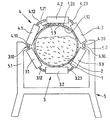
- Die Zeichnung erläutert die vorliegende Erfindung anhand einer stark vereinfachten Darstellung ihrer wesentlichen Merkmale:
- Der zu einem Schlauchband geformte und das Fördergut 2 einschliessende Fördergurt 1, der in bekannter Weise z. B. aus einem synthetischen Kautschuk hergestellt ist, wird an der unteren Hälfte seines Querschnitts durch die Rollen 3.1, 3.2 und 3.3 der unteren Rollengirlande 3 abgestützt während die obere Hälfte seines Querschnitts durch die Rollen 4.1, 4.2 und 4.3 der oberen Rollengirlande 4 so geführt wird, dass die Gurtränder 1.10 und 1.20 einander überlappen.
- Wie beschrieben, enthält der Fördergurt nur in seinen einander überlappenden Randbereichen 1.10 und 1.20 eingebettete, in Längsrichtung durchlaufende Festigkeitsträger 1.3, z. B. in der Form von Stahldrahtseilen. Der Mittelteil des Gurtes kann übliche in Quer- oder Diagonalrichtung verlaufende, in der Zeichnung nicht dargestellte Verstärkungseinlagen enthalten, die als Durchschlagschutz dienen und die Tragfähigkeit des Gurtes erhöhen.
- Die Rollengirlanden 3 und 4 sind an den Schenkeln 5.1 und 5.2 des Traggestells 5 gelenkig gelagert, und die auf ihren Achsen drehbaren Rollen sind über Zwischenglieder 3.12, 3.23 bzw. 4.12, 4.23 gelenkig miteinander verbunden. Das verlängerte Zwischenglied 4.12 sorgt dafür, dass die Längskante 1.21 des übergeschlagenen Gurtrandes 1.20 einen auch bei Schwankungen des Gurtverlaufes ausreichenden Abstand zu der seitlich benachbarten Rolle 4.1 einhält, um Kollisionen der Gurtkante 1.21 mit der Stirnseite dieser Rolle 4.1 und somit Beschädigungen der Gurtkante zu vermeiden.
Claims (8)
Priority Applications (1)
| Application Number | Priority Date | Filing Date | Title |
|---|---|---|---|
| AT86102493T ATE39104T1 (de) | 1985-02-27 | 1986-02-26 | Schlauchbandfoerderanlage. |
Applications Claiming Priority (4)
| Application Number | Priority Date | Filing Date | Title |
|---|---|---|---|
| DE3506829 | 1985-02-27 | ||
| DE3506829 | 1985-02-27 | ||
| DE3538990 | 1985-11-02 | ||
| DE3538990 | 1985-11-02 |
Publications (2)
| Publication Number | Publication Date |
|---|---|
| EP0194509A1 EP0194509A1 (de) | 1986-09-17 |
| EP0194509B1 true EP0194509B1 (de) | 1988-12-07 |
Family
ID=25829787
Family Applications (1)
| Application Number | Title | Priority Date | Filing Date |
|---|---|---|---|
| EP86102493A Expired EP0194509B1 (de) | 1985-02-27 | 1986-02-26 | Schlauchbandförderanlage |
Country Status (6)
| Country | Link |
|---|---|
| US (1) | US4723653A (de) |
| EP (1) | EP0194509B1 (de) |
| AU (1) | AU580141B2 (de) |
| DE (1) | DE3661354D1 (de) |
| ES (1) | ES292551Y (de) |
| IN (1) | IN168071B (de) |
Families Citing this family (12)
| Publication number | Priority date | Publication date | Assignee | Title |
|---|---|---|---|---|
| DE3624122A1 (de) * | 1986-07-17 | 1988-01-21 | Continental Gummi Werke Ag | Schlauchband-foerderanlage |
| JPH0811604B2 (ja) * | 1986-11-28 | 1996-02-07 | 株式会社ブリヂストン | パイプコンベヤにおけるベルト案内装置 |
| JPH0784247B2 (ja) * | 1986-12-02 | 1995-09-13 | 株式会社ブリヂストン | ベルトコンベヤ装置 |
| DE3768817D1 (de) * | 1986-12-10 | 1991-04-25 | Orenstein & Koppel Ag | Schlauchband-foerderanlage. |
| DE3722838A1 (de) * | 1987-06-11 | 1988-12-29 | Pwh Anlagen & Systeme Gmbh | Verfahren und vorrichtung zur formgebung von gurtbaendern fuer das hindurchziehen durch tragrollenstationen |
| DE3724376A1 (de) * | 1987-06-12 | 1989-04-20 | Pwh Anlagen & Systeme Gmbh | Rollgurt |
| US5042646A (en) * | 1989-10-13 | 1991-08-27 | R. A. Beatty & Associates Pty. Ltd. | Pipe conveyor apparatus |
| DE19544026A1 (de) * | 1995-11-25 | 1997-05-28 | Habasit Gmbh | Schlauchfördergurt |
| DE19811411B4 (de) * | 1998-03-17 | 2007-06-06 | Phoenix Conveyor Belt Systems Gmbh | Fördergurt |
| US8033385B2 (en) * | 2007-05-15 | 2011-10-11 | Thyssenkrupp Foerdertechnik Gmbh | Steep angle pipe conveyor |
| WO2011116234A1 (en) * | 2010-03-17 | 2011-09-22 | ThyssenKrupp Robins, Inc. | Vertical pipe conveyor |
| DE102011050937A1 (de) * | 2011-06-08 | 2012-12-13 | ThyssenKrupp Fördertechnik GmbH | Fördergurtanlage |
Family Cites Families (12)
| Publication number | Priority date | Publication date | Assignee | Title |
|---|---|---|---|---|
| FR1600983A (de) * | 1968-03-20 | 1970-08-03 | ||
| FR1583066A (de) * | 1968-05-21 | 1969-10-17 | ||
| FR1603134A (de) * | 1968-07-08 | 1971-03-22 | ||
| DE1922636A1 (de) * | 1969-05-03 | 1970-11-05 | Krupp Gmbh | Steilfoerderanlage |
| US4144964A (en) * | 1974-04-22 | 1979-03-20 | Pneumatiques, Caoutchouc Manufacture Et Plastiques Kleber-Colombes | Flexible support designed to support the conveyor belt of a conveyor |
| DE2752410A1 (de) * | 1977-11-24 | 1979-05-31 | Richard Pott | Foerdervorrichtung mit einem aus gummielastischem material bestehenden foerdergurt mit mittig angeordnetem zugorgan |
| JPS5574905A (en) * | 1978-11-28 | 1980-06-05 | Kunio Hashimoto | Carrying method and equipment for powder material |
| JPS6124493Y2 (de) * | 1981-03-12 | 1986-07-23 | ||
| GB2124576B (en) * | 1982-07-30 | 1986-02-12 | Babcock Moxey Ltd | Endless belt conveyor systems |
| FI68029C (fi) * | 1983-01-04 | 1985-07-10 | Outokumpu Oy | Roerbandtransportoer |
| DE3313301C1 (de) * | 1983-04-13 | 1984-07-19 | Friedrich Wilhelm Paurat | Schlauchbandfoerderer,insbesondere fuer bergbauliche Untertagebetriebe |
| US4630726A (en) * | 1983-05-13 | 1986-12-23 | Haruo Okazaki | Tubular belt conveyor and a belt rolling up means of the same |
-
1986
- 1986-02-25 AU AU54059/86A patent/AU580141B2/en not_active Ceased
- 1986-02-26 ES ES1986292551U patent/ES292551Y/es not_active Expired
- 1986-02-26 DE DE8686102493T patent/DE3661354D1/de not_active Expired
- 1986-02-26 EP EP86102493A patent/EP0194509B1/de not_active Expired
- 1986-02-26 US US06/833,903 patent/US4723653A/en not_active Expired - Fee Related
- 1986-07-30 IN IN611/MAS/86A patent/IN168071B/en unknown
Also Published As
| Publication number | Publication date |
|---|---|
| EP0194509A1 (de) | 1986-09-17 |
| AU5405986A (en) | 1986-09-04 |
| DE3661354D1 (en) | 1989-01-12 |
| AU580141B2 (en) | 1989-01-05 |
| ES292551U (es) | 1986-08-01 |
| ES292551Y (es) | 1987-04-16 |
| US4723653A (en) | 1988-02-09 |
| IN168071B (de) | 1991-02-02 |
Similar Documents
| Publication | Publication Date | Title |
|---|---|---|
| DE3606129A1 (de) | Gurt-foerderanlage | |
| EP0194509B1 (de) | Schlauchbandförderanlage | |
| WO2012168337A1 (de) | Fördergurtanlage sowie fördergurt | |
| DE3612765A1 (de) | Rollgurt | |
| DE3122035C2 (de) | ||
| EP0456978A1 (de) | Greifer für den Transport von Erzeugnissen insbesondere flächigen Erzeugnissen | |
| DE69001045T2 (de) | Foerderband und fuehrungssystem dafuer. | |
| EP0253148B1 (de) | Schlauchband-Förderanlage | |
| EP0391247A2 (de) | Gurtförderer | |
| DE2913286A1 (de) | Foerdereinrichtung fuer schwere lasten | |
| DE3841660A1 (de) | Verfahren zum betreiben eines in einer kurve verlegten foerderbandes und kurvenbandfoerderer | |
| EP0498189B1 (de) | Kurvengängiges, dezentral antreibbares Gummigurtband | |
| DE19917368C2 (de) | Stetigförderer | |
| DE4219097A1 (de) | Kurvengaengiger haufwerkfoerderer, insbesondere fuer bergbauliche untertagebetriebe | |
| DE2031903C3 (de) | Gliederhandlauf für Fahrtreppen oder Personenförderbänder | |
| DE2912789C2 (de) | Plattenband | |
| DE2949858C2 (de) | Kluppenkettenbahn | |
| DE4028130A1 (de) | Gurtfoerderer | |
| EP0937663A1 (de) | Abstützvorrichtung | |
| DE3623006C2 (de) | ||
| EP1385647B1 (de) | Kettenziehmaschine zum kontinuierlichen ziehen von ziehgut | |
| DE907279C (de) | Bandfoerderer | |
| DE3131594C2 (de) | Kluppenkettenbahn | |
| DE3439362C1 (de) | Kette für einen Kettenförderer | |
| DE2420715A1 (de) | Entspeicherungsgeraet fuer schuettgut |
Legal Events
| Date | Code | Title | Description |
|---|---|---|---|
| PUAI | Public reference made under article 153(3) epc to a published international application that has entered the european phase |
Free format text: ORIGINAL CODE: 0009012 |
|
| AK | Designated contracting states |
Kind code of ref document: A1 Designated state(s): AT BE CH DE FR GB IT LI LU NL SE |
|
| 17P | Request for examination filed |
Effective date: 19860930 |
|
| 17Q | First examination report despatched |
Effective date: 19870508 |
|
| RAP1 | Party data changed (applicant data changed or rights of an application transferred) |
Owner name: CONTINENTAL AKTIENGESELLSCHAFT |
|
| GRAA | (expected) grant |
Free format text: ORIGINAL CODE: 0009210 |
|
| AK | Designated contracting states |
Kind code of ref document: B1 Designated state(s): AT BE CH DE FR GB IT LI LU NL SE |
|
| REF | Corresponds to: |
Ref document number: 39104 Country of ref document: AT Date of ref document: 19881215 Kind code of ref document: T |
|
| REF | Corresponds to: |
Ref document number: 3661354 Country of ref document: DE Date of ref document: 19890112 |
|
| ITF | It: translation for a ep patent filed | ||
| ET | Fr: translation filed | ||
| GBT | Gb: translation of ep patent filed (gb section 77(6)(a)/1977) | ||
| PLBE | No opposition filed within time limit |
Free format text: ORIGINAL CODE: 0009261 |
|
| STAA | Information on the status of an ep patent application or granted ep patent |
Free format text: STATUS: NO OPPOSITION FILED WITHIN TIME LIMIT |
|
| 26N | No opposition filed | ||
| ITTA | It: last paid annual fee | ||
| PGFP | Annual fee paid to national office [announced via postgrant information from national office to epo] |
Ref country code: GB Payment date: 19930106 Year of fee payment: 8 |
|
| PGFP | Annual fee paid to national office [announced via postgrant information from national office to epo] |
Ref country code: CH Payment date: 19930205 Year of fee payment: 8 |
|
| PGFP | Annual fee paid to national office [announced via postgrant information from national office to epo] |
Ref country code: LU Payment date: 19930224 Year of fee payment: 8 |
|
| PGFP | Annual fee paid to national office [announced via postgrant information from national office to epo] |
Ref country code: SE Payment date: 19930225 Year of fee payment: 8 Ref country code: FR Payment date: 19930225 Year of fee payment: 8 |
|
| PGFP | Annual fee paid to national office [announced via postgrant information from national office to epo] |
Ref country code: BE Payment date: 19930226 Year of fee payment: 8 Ref country code: AT Payment date: 19930226 Year of fee payment: 8 |
|
| PGFP | Annual fee paid to national office [announced via postgrant information from national office to epo] |
Ref country code: NL Payment date: 19930228 Year of fee payment: 8 |
|
| EPTA | Lu: last paid annual fee | ||
| PG25 | Lapsed in a contracting state [announced via postgrant information from national office to epo] |
Ref country code: LU Free format text: LAPSE BECAUSE OF NON-PAYMENT OF DUE FEES Effective date: 19940226 Ref country code: GB Effective date: 19940226 Ref country code: AT Effective date: 19940226 |
|
| PG25 | Lapsed in a contracting state [announced via postgrant information from national office to epo] |
Ref country code: SE Effective date: 19940227 |
|
| PG25 | Lapsed in a contracting state [announced via postgrant information from national office to epo] |
Ref country code: LI Effective date: 19940228 Ref country code: CH Effective date: 19940228 Ref country code: BE Effective date: 19940228 |
|
| BERE | Be: lapsed |
Owner name: CONTINENTAL A.G. Effective date: 19940228 |
|
| PG25 | Lapsed in a contracting state [announced via postgrant information from national office to epo] |
Ref country code: NL Effective date: 19940901 |
|
| NLV4 | Nl: lapsed or anulled due to non-payment of the annual fee | ||
| GBPC | Gb: european patent ceased through non-payment of renewal fee |
Effective date: 19940226 |
|
| PG25 | Lapsed in a contracting state [announced via postgrant information from national office to epo] |
Ref country code: FR Effective date: 19941031 |
|
| REG | Reference to a national code |
Ref country code: CH Ref legal event code: PL |
|
| REG | Reference to a national code |
Ref country code: FR Ref legal event code: ST |
|
| EUG | Se: european patent has lapsed |
Ref document number: 86102493.3 Effective date: 19940910 |
|
| PGFP | Annual fee paid to national office [announced via postgrant information from national office to epo] |
Ref country code: DE Payment date: 19950413 Year of fee payment: 10 |
|
| PG25 | Lapsed in a contracting state [announced via postgrant information from national office to epo] |
Ref country code: DE Effective date: 19961101 |
|
| PG25 | Lapsed in a contracting state [announced via postgrant information from national office to epo] |
Ref country code: IT Free format text: LAPSE BECAUSE OF NON-PAYMENT OF DUE FEES;WARNING: LAPSES OF ITALIAN PATENTS WITH EFFECTIVE DATE BEFORE 2007 MAY HAVE OCCURRED AT ANY TIME BEFORE 2007. THE CORRECT EFFECTIVE DATE MAY BE DIFFERENT FROM THE ONE RECORDED. Effective date: 20050226 |