EP0195219A2 - Abgeschrecktes permanentmagnetisches Material - Google Patents
Abgeschrecktes permanentmagnetisches Material Download PDFInfo
- Publication number
- EP0195219A2 EP0195219A2 EP86101510A EP86101510A EP0195219A2 EP 0195219 A2 EP0195219 A2 EP 0195219A2 EP 86101510 A EP86101510 A EP 86101510A EP 86101510 A EP86101510 A EP 86101510A EP 0195219 A2 EP0195219 A2 EP 0195219A2
- Authority
- EP
- European Patent Office
- Prior art keywords
- magnetic
- alloy material
- magnetic alloy
- ribbon
- boron
- Prior art date
- Legal status (The legal status is an assumption and is not a legal conclusion. Google has not performed a legal analysis and makes no representation as to the accuracy of the status listed.)
- Granted
Links
Images


Classifications
-
- B—PERFORMING OPERATIONS; TRANSPORTING
- B82—NANOTECHNOLOGY
- B82Y—SPECIFIC USES OR APPLICATIONS OF NANOSTRUCTURES; MEASUREMENT OR ANALYSIS OF NANOSTRUCTURES; MANUFACTURE OR TREATMENT OF NANOSTRUCTURES
- B82Y25/00—Nanomagnetism, e.g. magnetoimpedance, anisotropic magnetoresistance, giant magnetoresistance or tunneling magnetoresistance
-
- H—ELECTRICITY
- H01—ELECTRIC ELEMENTS
- H01F—MAGNETS; INDUCTANCES; TRANSFORMERS; SELECTION OF MATERIALS FOR THEIR MAGNETIC PROPERTIES
- H01F1/00—Magnets or magnetic bodies characterised by the magnetic materials therefor; Selection of materials for their magnetic properties
-
- H—ELECTRICITY
- H01—ELECTRIC ELEMENTS
- H01F—MAGNETS; INDUCTANCES; TRANSFORMERS; SELECTION OF MATERIALS FOR THEIR MAGNETIC PROPERTIES
- H01F1/00—Magnets or magnetic bodies characterised by the magnetic materials therefor; Selection of materials for their magnetic properties
- H01F1/01—Magnets or magnetic bodies characterised by the magnetic materials therefor; Selection of materials for their magnetic properties of inorganic materials
- H01F1/03—Magnets or magnetic bodies characterised by the magnetic materials therefor; Selection of materials for their magnetic properties of inorganic materials characterised by their coercivity
- H01F1/032—Magnets or magnetic bodies characterised by the magnetic materials therefor; Selection of materials for their magnetic properties of inorganic materials characterised by their coercivity of hard-magnetic materials
- H01F1/04—Magnets or magnetic bodies characterised by the magnetic materials therefor; Selection of materials for their magnetic properties of inorganic materials characterised by their coercivity of hard-magnetic materials metals or alloys
- H01F1/047—Alloys characterised by their composition
- H01F1/053—Alloys characterised by their composition containing rare earth metals
- H01F1/055—Alloys characterised by their composition containing rare earth metals and magnetic transition metals, e.g. SmCo5
- H01F1/057—Alloys characterised by their composition containing rare earth metals and magnetic transition metals, e.g. SmCo5 and IIIa elements, e.g. Nd2Fe14B
- H01F1/0571—Alloys characterised by their composition containing rare earth metals and magnetic transition metals, e.g. SmCo5 and IIIa elements, e.g. Nd2Fe14B in the form of particles, e.g. rapid quenched powders or ribbon flakes
-
- H—ELECTRICITY
- H01—ELECTRIC ELEMENTS
- H01F—MAGNETS; INDUCTANCES; TRANSFORMERS; SELECTION OF MATERIALS FOR THEIR MAGNETIC PROPERTIES
- H01F1/00—Magnets or magnetic bodies characterised by the magnetic materials therefor; Selection of materials for their magnetic properties
- H01F1/01—Magnets or magnetic bodies characterised by the magnetic materials therefor; Selection of materials for their magnetic properties of inorganic materials
- H01F1/03—Magnets or magnetic bodies characterised by the magnetic materials therefor; Selection of materials for their magnetic properties of inorganic materials characterised by their coercivity
- H01F1/032—Magnets or magnetic bodies characterised by the magnetic materials therefor; Selection of materials for their magnetic properties of inorganic materials characterised by their coercivity of hard-magnetic materials
- H01F1/04—Magnets or magnetic bodies characterised by the magnetic materials therefor; Selection of materials for their magnetic properties of inorganic materials characterised by their coercivity of hard-magnetic materials metals or alloys
- H01F1/047—Alloys characterised by their composition
- H01F1/053—Alloys characterised by their composition containing rare earth metals
- H01F1/055—Alloys characterised by their composition containing rare earth metals and magnetic transition metals, e.g. SmCo5
- H01F1/057—Alloys characterised by their composition containing rare earth metals and magnetic transition metals, e.g. SmCo5 and IIIa elements, e.g. Nd2Fe14B
- H01F1/0579—Alloys characterised by their composition containing rare earth metals and magnetic transition metals, e.g. SmCo5 and IIIa elements, e.g. Nd2Fe14B with exchange spin coupling between hard and soft nanophases, e.g. nanocomposite spring magnets
Definitions
- the invention relates to permanent magnetic alloy materials, bodies thereof and methods of preparing them.
- good permanent magnetic materials e.g., having maximum magnetic energy products above about 15 megagaussoersteds, consist of a conglomeration of non-interacting substantially crystallographically oriented uniaxial particles.
- M s maximum or saturation value of the net magnetization
- the magnetization vector, M lies along the c axis for a zero applied field. If a field is applied in an arbitrary direction z, the magnetization is rotated away from the c axis until, at sufficiently large fields, M is parallel to z and M z is equal to M s . When the field is removed, the magnetization relaxes back parallel to the c axis, subject to the condition that the projection of magnetization along the c axis is positive.
- Anisotropic materials have at least one magnetic property which is a strong function of the direction of measurement Such materials are characterized by a single "easy direction" of magnetization, where the value of the property greatly exceeds the value in other directions of magnetfz- ation. If the particles are non-interacting, the maximum energy product varies from a maximum value of 0.25 (M s ) 2 , when z is parallel to the c axis, to 0 when z is perpendicular to the c axis. For a theoretical anisotropic material with M s equal to 16 and He chosen to be greater than M s , the maximum theoretical value of the energy product of the hysteresis loop is 64 megagaussoersteds.
- the teaching of the prior art for a perfectly oriented non-interacting material is that the maximum energy product is four (4) times that of the same material when randomly oriented (isotropic)-For a general distribution of orientations of non-interacting particles, as a consequence of simple vector geometry, where theta is the angle between the applied field and the easy axis of a given particle, and the result represents the size weighted average over all of the particles.
- M r /M s 1 along the direction of orientation of a perfectly oriented, non-interacting, permanent magnet sample (anisotropic)
- M r /M s 0.5 in all directions for a completely unoriented, non-interacting sample (isotropic).
- a figure of merit which applicants refer to as the magnetic retention parameter, is where M s and M r are measured with the applied magnetic field along three orthogonal directions.
- Q approaches 1 for perfectiy oriented, non-interacting, particles or crystallites - (anisotropic) and 0.75 for completely unoriented, non-interacting, crystallites (isotropic).
- the behavior for reported values of permanent magnetic materials of the prior art tend to produce values of Q which are substantially below the theoretical values. See, e.g., McCurrie; Herbst and Tracy; and Stoner and Wohlfarth; above.
- the samarium-cobalt alloy system - (generally SmCo s or Sm 2 Co 17 ).
- the samarium-cobalt system achieves improved magnetic parameters over ferrites, Al- nico and other conventional permanent materials but utilizes more expensive materials and processes.
- the samarium-cobalt alloy system is rich in samarium, which is expensive to separate from the other, more abundant rare earth metals, and in cobalt, which is a strategic metal and possibly hard to obtain.
- a second prior art alloy system is the rare earth -iron - boron system (RE-Fe-B).
- RE-Fe-B The exemplary magnetic properties of the RE-Fe-B system have been attributed to the compound RE 2 Fe 14 B. The existence of this compound was first reported by N.F. Chaban, Y.B. Kuzma, N.S. Bilonoz- hko, O.O. Kachmar, and N.V. Petrov, in Ternary (Nd. Sm. Gd) -Fe -B Svstems, Dopv. Akad. Nauk. Ukr. RSR, Ser. A, No. 10, pages 873-8 7 5 (April 1979).
- GM II Yelon, Structural and Maonetic Properties of Nd 2 -Fe 14 -B, J. Appl. Phys., Vol. 57, No. 1, pp. 4086-4090 (April 1985), (GM II).
- GM I analyzed the stoichiometry and crystal structure of ingot material using Rietveld refined neutron powder diffraction data, as described hereinbelow, taken at 673 degrees Kelvin and at room temperature on a position sensitive detector-diffractometer.
- GM I reports the stoichiometry to be RE 2 Fe 14 B and the space group to be P4 2 /mnm.
- the rare earth component being neodymium - (Nd)
- the site designations, occupancies, positions, and lattice parameters are reported as shown in Table I below.
- GM II the atom positions and lattice parameters were redetermined based on measurements of what was stated to be a better ingot material than that of GM I.
- the positions and lattice parameters are shown in Table II, below.
- GM II states that melt spun ribbons with the maximum energy product of 14.1 megagaussoersteds consist almost totally of the Nd 2 Fe 14 B phase with some residual iron and no other identifiable second phase.
- the atomic position parameters of the melt spun material in GM II are identical to that of the ingot material within 0.003 of those shown in Table II.
- the prior art RE-Fe-B system has been investigated in the form of both anisotropic and isotropic materials.
- Isotropic RE-Fe-B magnetic materials have been prepared by the process of melt spinning.
- the isotropic materials include the GM materials referred to above, when formed from the melt spinning process.
- GM Croat, et al, Japanese laid open Patent Application 60-9852 claiming the benefit of U.S. Patent Application Serial No. 508,266 filed June 24, 1983 for High Enerav Product Rare Earth Iron Magnet Alloys, U.S. Patent Application Serial No. 544,728 filed October 26, 1983 for High Energy Product Rare Earth-Iron Magnet Allovs, and U.S. Application Serial No. 414,936, filed September 3, 1982 for High Enerov Product Rare Earth Iron Magnet Alloys) claims to have identified specific quench parameter ranges, emphasizing wheel speed, necessary to obtain maxima of isotropic magnetic properties.
- the melt spun materials have low coercivity, low remanance, and low maximum energy products significantly degraded from the peak reported values.
- the above peak reported values of the highest energy product rare earth -iron -boron alloys have been limited to an isotropic maximum magnetic energy product of about 14.1 megagaussoersteds, a remanent of less than about 8.5 kilogauss and a coercivity on the order of 15 kilooersteds.
- Anisotropic rare earth -iron -boron magnetic materials have heretofore been prepared by two different processes.
- One process is a melt spinning -hot press - die upset process (referred hereinafter as the die upset process).
- the die upset process is described in R.W. Lee, "Hot Pressed Neodymium-Iron-Boron Magnets", Appl. Phys. Lett-, Vol. 46(8), pages 790-791 (April 1985), and European Patent Application 0-133-758 claiming the benefit of U.S. Application Serial No. 520,170, field August 4, 1983 by R.W. Lee for "Iron-Rare Earth-Boron Magnets by Hot Working".
- the Lee (GM) paper describes placing melt spun ribbon fragments into a high temperature die and, applying uniaxial pressure to achieve densification.
- the coercivity was approximately 1 9.5 kilooersteds in all directions of measurement
- the densified material is then "die upset", i.e., hot pressed in a second, larger diameter die press.
- the Lee paper reports that the second hot press, i.e., the "die upset", introduces crystallographic orientation.
- Energy products of as high as 40 megagaussoersteds were reported after die upsetting.
- the coercivity was reduced to 12.5 kilooersteds measured parallel to crystallographic orientation and 15.5 kilooersteds measured perpendicular to crystallographic orientation.
- the second process is a consolidate -cast -crush - grind -magnetic alignement -hot press -sinter process which has been described in European Laid Open Patent Application 0-101-552-12 (Application No.83-106573.5) of Masato Sagawa, Setsuo Fujimura, and Yutoka Matsuura for Maonetic Materials and Permanent Magnets, claiming the benefit of Japanese Patent Applications (i) 145072/82 filed August 21, 1 982, (ii) 200204/82 filed November 15, 1982, - (iii) 5814/83 filed January 19, 1983, (iv) 37896/83 filed March 8, 1983, (v) 37898183 filed March 9, 1983, (vi) 84859/83 filed May 14, 1983, and (vii) 94876/83 filed May 31, 1983, and in M.
- This multi-step process starts with a soft magnetic alloy, and, only after crushing, grinding, magnetic aligning, pressing, and sintering, yields a sintered magnetic anisotropic material body having a magnetic energy product of as high as 36.5 megagaussoersteds, a coercive force of about 9.0 kilooersteds, and a remanant of about 12.6 kilogauss.
- the materials disclosed in these patents are formed in a solid amorphous host matrix having structural configurations which have local rather than long- range order. According to the principle, a modification material is added to the host matrix, which material has orbitals which interact with the host matrix as well as with themselves. This interaction substantially modifies the electronic configurations of the host matrix. These materials have on an atomic or microscopic level atomic configurations substantially changed to provide, e.g., independently increased electrical conductivity.
- Modification has been effected in a number of ways, e.g., diffusion in, co-depositing, excited gas modification, double nozzle melt spinning, compositional modification, layering, or incorporation in the melt
- the prior art isotropic materials have fairly low magnetic properties.
- the prior art teaches that anisotropic materials are necessary for any significant improvement of magnetic parameters.
- the prior art methods form the anisotropic materials by utilizing further expensive and time consuming processes, which materials are summarized in Table IV.
- a permanent magnetic alloy which exhibits superior magnetic prop- ert i es as measured in all spatial directions, that is, isotropically.
- the magnetic parameters are of a magnitude which the prior art teaches to be only attainable in one spatial direction that is anisotropically, and to be only attainable with aligned materials.
- the magnetic material of the present invention has a ratio of net remanent magnetization (M r ) to net saturation magnetization (M s ), exceeding 0.5 and approaching 1.0, in all directions, without any significant preferred crystalline orientation.
- the herein contemplated permanent magnetic materials have a magnetic retention parameter, Q, as described above, greater than 1.
- the theoretical limit of the magnetic retention parameter, Q, for the herein contemplated materials is believed to be 3, rather than the theoretical values of 1.0 and 0.75 for aligned (anisotropic) and unaligned - (isotropic), non-interacting materials of the prior art.
- Ribbon samples of the as quenched material can, without further processing, exhibit remanant magnetization, M r , greater than 9 kilogauss, coercive force, H c , greater than 8 kilooersteds, and preferably greater than 11 kilooersteds, and maximum energy product (BH)max greater than 15 megagaussoersteds with similar values measured in all directions, i.e., in the place of the ribbon and perpendicular to the plane of the ribbon. In the latter case the value was obtained after a standard correction (demagnetization factor) for the shape anisotropy of the ribbon.
- the saturation magnetization M s of the ribbon i.e., the magnetization in the limit or large applied fields, is estimated to be 15 to 1 5.5 kilogauss, also in all directions.
- the values correspond to the value of M r /M s greater than 0.6, and a magnetic retention parameter, Q, greater than 1, in contradistinction to the clear teachings of the prior art for a macroscopically isotropic, non-interacting material.
- Typical magnetic parameters for the magnetic alloys of 'the invention are as shown in Table V below.
- the as spun ribbon material may be further processed to produce compacted magnetic bodies. It is possible that some amount of magnetic anisotropy may be created in the material as an effect of the processing steps used.
- the samples of the materials of the present invention made by the herein disclosed method exhibit superior relevant magnetic parameters when compared with the isotropic materials of the prior art listed in Table III.
- the samples of the present invention exhibit comparable magnetic properties, and were prepared without the costly, complicated alignment steps necessary in the prior art.
- a magnetic alloy material having superior magnetic properties, methods of synthesizing the magnetic alloy material, compacted bodies of the magnetic alloy material, and methods of forming the compacted bodies of the magnetic alloy material.
- the alloy is a substantially crystallographically unoriented, magnetically isotropic alloy. It is a permanent hard magnet, preferably with an isotropic maximum magnetic energy greater than 15 megagaussoersteds, and a magnetic retention parameter, Q, greater than 1.0
- the magnetic alloy material has a maximum magnetic energy product, (BxH) max , of at least about 15 megagaussoersteds, a coercivity of above about 8 kilooersteds, and a remanence of above about 9 kilogauss, and preferably above about 11 kilogauss.
- Ribbon samples of the as quenched material can, without further processing, exhibit remanent magnetization, M r ,greater than 9 kilogauss, coercive force, H c , greater than 8 kilooersteds, and maximum energy product, (BH) max , greater than 15 megagaussoersteds with similar values measured in all directions, i.e., in the plane of the ribbon and perpendicular to the plane of the ribbon. In the latter case the value was after a standard correction - (demagnetization factor) for the shape anisotropy of the ribbon.
- the saturation magnetization M s of the ribbon i.e., the magnetization in the limit of large applied fields, is estimated to be 15 to 15.5 kilogauss, also in all directions. These values correspond to a value of M r /M s greater than 0.6, and a magnetic retention parameter, Q, greater than 1, in contradistinction to the clear teachings of the prior art for a macroscopically isotropic material.
- the magnetic alloy material is an alloy of iron, optionally with other transition metals, as cobalt a rare earth metal or metals, boron, and a modifier.
- a modifier is an alloying element or elements added to a magnetic material which serve to improve the isotropic magnetic properties of the resultant material, when combined with the unmodified material by an appropriate processing technique.
- exemplary modifiers are silicon, aluminum, and mixtures thereof.
- Alternative or additional modifiers may include lithium, hydrogen, fluorine, phosphorous, sulfur, germanium, and carbon.
- the amount of modifier is at a level, in combination with the quench parameters, to give the above described isotropic magnetic parameters and the below described x-ray pattern.
- the magnetic alloy may be of the type
- the magnetic alloy material has the stoichiometry represented by:
- the rare earth metal is a lanthanide chosen from neodymium and praseodymium, optionally with other lanthanides (one or more La, Ce, Sm, Eu, Gd, Tb, Dy, Ho, Er, Tm, Yb and Lu), So, Y, and mixtures thereof present While various combinations of the rare earth metals may be used without departing from the concept of this invention, especially preferred rare earth metals are those that exhibit one or more of the following characteristics : (1) the number of f-shell electrons is neither 0 (as La), 7 (as Gd) or 14 (as Lu), (2) low molecular weight lanthanides, such as La, Ce, Pr, Nd, and Sm, (3) high magnetic moment lanthanides that couple ferromagnetically with iron, as Nd and Pr, or (4) relatively inexpensive lanthanides, as La, Ce, Pr, and Nd. Especially preferred are Nd and Pr. Various commercial and/or byproduct mischmetals may be used. Especially preferred
- silicon, aluminum, or silicon and aluminum may modify the thermodynamic pathway to solidification, resulting in a modified material and may promote the formation of intergranular phases and/or particle-particle interactions that enhance the magnetic properties of the rapidly quenched magnetic alloy material-In high remanence materials, the majority of the material is fine grained such that the metallographic grains are not resolvable by polishing and etching, e.g., in 1 to 2 percent nitric acid in ethanol, and are not observable by scanning electron microscopy, having a resolution of 2000 Angstroms.
- the alloy has a crystallographic structure having a Rietveld refined x-ray powder diffraction pattern consistent with (1) the presence of a major portion of a tetragonal rare earth -iron -boron type phase, modified in atomic occupancy and lattice parameters from the prior art rare earth -iron - boron type material by the presence of a modifier, as Si and/or Al, and (2) an alpha -iron phase, optionally with other phases being present below the level of detection by x-ray diffraction.
- a modifier as Si and/or Al
- the hard magnetic alloy material has a crystallographic structure exhibiting a Rietveld refined x-ray powder diffraction pattern consistent with the presence of a major portion of a tetragonal phase with the structure P4 2 /mnm, and composed of RE-Fe-B, RE-Fe-B-Si, RE-Fe-B-(Si,Al), or RE-Fe-B-AI, of a body centered cubic alpha-iron phase, and possibly other exsolved phases below the level of detection of x-ray diffraction. Additionally, the Rietveld refined x-ray powder diffraction pattern is consistent with a shift in the boron position relative to that in the unmodified material, such shift increasing with increasing Si content at the Si concentrations of interest.
- Rietveld analysis is described by R.A. Young and D.B. Wiles in Application of the Rietveld Method for Structure Refinement with Powder Diffraction Data. Adv, in X-Ray Anal., Vol. 24, pp. 1-24 (1981; and in Profile ShaDe Functions in Rietveld Refinements, J. Appl. CrysL, Vol. 15, pp. 430-438 (1982).).
- Rietveld analysis starts with powder diffraction data, e.g., x-ray diffraction data or neutron diffraction data, and produces refined values of the structural parameters therefrom.
- Rietveld analysis uses least squares methodology to obtain a best fit between the entire calculated powder diffraction patterns as a whole. In this way, it is possible to obtain such structural parameters as atomic co-ordinates, thermal motion, and site occupancy parameters.
- One typical magnetic alloy material of the invention has the occupancies, crystal lattice parameters, and scale factor, based on Rietveld refinement of x-ray diffraction data, as shown on Table VI:
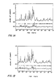
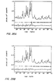
- the magnetic alloy materials of the invention have the Rietveld refined x-ray diffraction pattern shown in FIGURES 1 A and 1 B.
- FIGURES 1A and 1B are Rietveld refined powder x-ray diffraction patterns for powdered magnetic ribbon sample number 376AV08 (see example No. 7 for composition and other details).
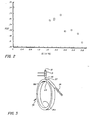
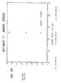
- FIGURE 2 is a plot of the boron lattice position versus silicon content. Additions of silicon are seen to correlate with the progressive shift of the boron lattice position within the tetragonal rare earth -iron -boron lattice, with respect to the Rietveld refined neutron diffraction data of GM II for the silicon-free rare earth -iron -boron tetragonal material. This is outside the range of experimental error, and is consistent with a non-interstitial location of silicon in.the lattice.
- One means of producing the above described, magnetic alloy having magnetic isotropy and the above crystallographic properties is by melt spinning, i.e., rapidly solidifying and quenching molten alloy material onto a moving chill surface, e.g., a rotating chill surface means substantially as shown in FIGURE 3.
- Molten alloy material 21 contained in a crucible 31 is dischaged through an orifice 33 onto a chill surface means 35.
- the chill surface means 35 e.g., a wheel 35A with a diameter of from about 10 inches (25 centimeters) to about 60 inches (1.5 meters) or more, having a thermally conductive surface 35B thereon, moves with respect to the orifice 33, e.g., rotating at a linear velocity of about 17 to 35 meters per second.
- Optimum wheel speeds are dependent on other process control parameters, specifically those affecting mass flow rate.
- the molten material 21 forms a molten puddle 23 on the thermally conductive surface 35B of the chill surface means 35.
- a ribbon, wire, or filament 25 forms at the interface of the puddle 23 with the thermally conductive surface 35B as heat is conducted out of the solidifying material into and through the conductive surface 35B of the chill surface means 35.
- the velocity of the solidification front and the direction of the solidification front 27 with respect to the chill surface 35B determine the magnetic properties of the material.
- the orientation and velocity of the solidification front 27 and the thermal gradient across the front as well as grain coarseness are believed to be functions of the quench parameters, and interactions therebetween i.e.,
- a substantially homogeneous quenched alloy of the invention it is essential to have a substantially homogeneous melt. In one embodiment this is insured by first reacting the constituent elements to form a macroscopically homogeneous mother alloy. It is believed that the presence of silicon and/or other modifier in the melt promotes the high homogeneity observed.
- the quench parameters may be controlled to direct the solidification front 27, control its velocity, and control grain coarseness.
- FIGURE 4 is a representation of the puddle 23, the ribbon 25, and the solidification front 27 where the quench parameters are controlled to provide desired velocity of the solidification front 27, and rates of grain growth.
- the alloy is quenched at an appropriate rate to result in electronic,, atomic, crystallographic and morphological structures and configurations that give rise to the novel magnetic properties.
- the quench parameters are carefully controlled to produce an appropriate fine grained structure, which, together with the aforementioned modifier, results in the desired permanent magnet material.
- the alloy may be quenched at a rate sufficient to produce a precursor microstructure, which, when appropriately heat treated, results in a structure exhibiting the above described improved magnetic parameters
- Individual melt spun fragments are recovered as product from the melt spinning process. Individual particles can also be obtained by the comminution of the ribbon fragments which are generally relatively brittle.
- the ribbon fractures, yielding particles, e.g., flake like particles, or plate like individual particles 11 shown in Figure 5.
- the individual particles when shaken or agitated, stack with their major surfaces 13 arrayed substantially parallel.
- a practical advantage of the particulate magnetic material is the ease of subsequent formation and fabrication into an end-use product. Since the magnetic particles of the present invention are isotropic in their magnetic behavior, they can be pressed and compacted without regard for any particular crystalline orientation and/or magnetic alignment. Thus, according to one embodiment of the invention, ribbon material can be further reduced in size to, e.g., 0.5 millimeter in the largest dimension, cold pressed, and bonded. In this way, magnetic powder densities above about 70 percent may be obtained, with (BH) max values greater than 50 percent of the original, fully dense starting material.
- the magnetic materials of the invention can be pressed to above about 90 percent of theoretical density, without a magnetic alignment step, while still retaining the enhanced magnetic properties of the material.
- the ribbon 25 may be compacted as cast, i.e., from ribbons, having thicknesses of 15 to 70 microns, widths of up to tens of millimeters, and lengths of 1 to tens of millimeters.
- the ribbons may be broken into smaller pieces, for example having a size of about ten microns to about hundreds of microns in the longer dimension, and from about 1 0 microns to about 1 00 microns in the shortest dimension.
- the ribbon may self- comminute during the quench process into flakes, plates, platelets, or particles.
- Individual particles 11 are obtained by comminution, that is size reduction, of the ribbon 25, which is generally relatively brittle, or as fragments, e.g., plates or flakes directly from the chill surface.
- the ribbon 25 fractures, yielding individual particles, 1 1.
- Comminution may be by grinding, micromilling, ball milling, or impact milling, among others.
- the particles have a particle size as described above.
- the individual particles 11, may, after comminution, be coated, for example, with organic or inorganic lubricants, as graphite and MoS z .
- the coating may be carried out, for example, by blending.
- organic lubricant is "Acrawax", an organic lubricant in the form of 1 to 10 micron spheres that bum off at about 120°C. leaving a slight residue.
- the individual particles 11 may be stacked, for example, by ultrasonic signals, vibrating, shaking or agitating, with their major surfaces arrayed substantially in parallel, which may assist in compaction.
- the particles are then agglomerated or consolidated. Consolidation initially involves compaction. Compaction may be by cold pressing, followed by a separate sintering process, or by hot pressing. Alternatively, compaction may be carried out by die upset, extrusion, forging, rolling, or the like.
- Pressing may also include shaping into useful shapes, as where extrusion is incorporated into the pressing process.
- the loose particles may be pressed to form the desired shaped article and may be thereafter sintered to form the desired mechanically hard article.
- Sintering is carried out in a non-oxidizing atmosphere and causes the individual particles 1 1 to form a single mass. Sintering is carried out at temperatures from about 450°C to about 900°C. Heating may reduce the magnetic parameters of individual fragments of magnetic material. However, the maximum energy product increases with the square of the density of a magnetic body, and compaction may increase the net magnetic properties of the body.
- Compaction and consolidation may be by drop forging, as in a process including a semisinter, e.g., at about 650°C to 750°C for under one hour, followed by hot forging, e.g., with a cold die, and the heated, semisintered, hard magnet material, at a pressure of about 20,000 pounds per square inch to about 250,000 pounds per square inch.
- a semisinter e.g., at about 650°C to 750°C for under one hour
- hot forging e.g., with a cold die
- the heated, semisintered, hard magnet material at a pressure of about 20,000 pounds per square inch to about 250,000 pounds per square inch.
- compaction and consolidation is carried out by cold pressing, at a pressure of about 100,000 to 250,000 Ibs./in. 2 and preferably about 160,000 Ibs/in 2 , followed by hot pressing at temperatures of about 450 to 900°C for about 1 hour.
- compaction and consolidation may be carried out using the hot press - die upset technique of R.W. Lee, described herein above.
- the hot press -die upset process the melt spun ribbon fragments or particles are uniaxially hot pressed in a high temperature die, e.g., a die heated to about 700°C. This results in plastic deformation of the particles.
- the partially consolidated, compacted material is then "die upset". That is, it is hot pressed a second time in a die of larger diameter.
- the hard magnetic material may be compacted and consolidated by rapid omnidirectional consolidation.
- This process is described in U.S. Patent 4 ,341,557 of James R. Lizenby for Method of Hot Consolidatino Powder With A Recyclable Container Material Published European Patent Application 94164 of James R. Lizenby for Formino Dense Powder Comoact Usino Pressure Transmitting Medium, and James R. Lizenby, Wafter J. Rozmus, James L Bamard, and Clifford A. Kelto, Fluid Die Press Consolidation, in Pap. Powder Metal, Superalloys, Met Powder Rep. Conf., (1980), Vol.2, Paper #12, MPR Publ- Serv. Ltd., Shrewsbury, UK.
- the magnetic material powders or particles are subjected to temperatures and pressures sufficient to compact the magnetic material, and deform the container material.
- the hot pressing temperature is between the plastic deformation and melting temperatures of the container materials.
- a thin walled container is filled with particles, flakes, or powder of the magnetic material.
- a pressure transmission medium is then cast around the thin walled container inside a mold.
- Exemplary pressure transmission media have low plastic deformation temperatures, e.g., copper, copper/nickel alloys, and ceramic and glass frits.
- the container is heated to the plastic deformation temperature of the pressure transmission medium, and placed in a fitting pot die.
- the container, pressure transmission medium, and magnetic material are then rammed to pressurize the pressure transmission medium, applying a hydrostatic pressure to the container, and compacting and consolidating the magnetic material.
- the magnetic materials may be compacted and consolidated in an organic polymer, e.g., by pressing, extrusion, die forming, injection molding or the like.
- exemplary materials include nylons, polyethers, polyepoxides, polyalkyls, polycarbonates, and polyurethanes among others.
- a precursor alloy or mother alloy may be prepared containing from about 10 to 14 atomic percent total Nd or Pr, about 5 to 10 atomic percent B, about 1 to 5.0 atomic percent silicon, balance Fe, by radio frequency induction melting at above 1200°C and especially about 1600°C for about 30 minutes to about 2 hours under an inert atmosphere, e.g., an argon atmosphere in an MgO crucible.
- an inert atmosphere e.g., an argon atmosphere in an MgO crucible.
- a portion of the mother alloy may be placed in a crucible 31, as a quartz crucible, having a 0.5 to 1.5 mm diameter orifice and especially a 0.7 mm to 1.0 mm diameter orifice 33 spaced about 0.20 to 0.30 inch (5 to 9 millimeters) from the chill surface 35B, at an angle of about 85° to 90°, in operative relationship to chill surface means 35.
- the alloy 21 in the crucible 31 is melted under an argon atmosphere, and then discharged under an argon head of about 150 millimeters of mercury onto chill surface means 35 having a rotating chill surface 35B on a 20 inch diameter (58 centimeter) chill wheel 35A, rotating with a surface velocity of about 20 to 30 meters/second.
- the resulting brittle ribbon has a thickness of about 20 to 70 microns and preferably 30 to 40 microns, and a width of about 1 to about 5 millimeters.
- the magnetically isotropic particles 11 have a magnetic retention parameter, Q, above about 1.0, a maximum magnetic energy product of above about 15 megagaussoersted, and frequently above about 20 megagaussoersteds, and a remanance of above about 9 kilogauss.
- the particles may be compacted to form a magnetic body. After comminution by hand milling, micromilling, and/or impact milling to a particle size of about 10 to about hundreds of microns in the longest dimension, the particles may be blended with an organic lubricant The lubricant leaves round lubricant beads on the individual magnetic particles.
- the particles are pressed, for example, by cold pressing at a pressure of about 160,000 Ibs./in. 2 , and generally from about 80,000 to about 225,00 Ibs./in. 2 whereby to form a compact
- the compact is then heated to effect consolidation. Typically the heating may be within a temperature range of from about 450°C to about 1160°C for about 1 hour to about 9 hours.
- the resulting compacted, consolidated, hard magnetic bodies typically have an isotropic magnetic energy product of about 15 or more megagaussoersteds and a magnetic retention parameter, Q, greater than 1.
- a macroscopically homogeneous ingot (mother alloy) was first prepared by melting together the proper mixture of iron, neodymium, praseodymium, boron, silicon, and aluminum. Thereafter, each ingot was rapidly quenched using melt-spinning to form fragments of ribbon. These as-quenched ribbon samples were individually weighed and measured magnetically, generally using a large pulsed field to pre- magnetize the samples. In some cases, the ribbon samples were subjected to further heat-treatment and subsequently remeasured magnetically. Both the ingot and the final ribbon samples were examined in a scanning electron microscope for microstructure and elemental composition.
- the precursor or mother alloys were generally prepared from the elemental components: iron (99.99% pure electrolytic iron flake), boron (99.7% crystalline boron), Nd and Pr pure rods (99.9% rare earth metals), and silicon (99.99% Si crystals). In some cases, higher purity material was used. In other cases, commercial-grade rare-earth products were used, containing up to 15 weight % iron and up to several weight % of rare earths other than Nd and Pr. The components were weighed out in appropriate proportions, and melted together either by arc-melting on a cooled copper hearth, or by rf induction heating in a crucible consisting either of fused quartz or sintered magnesium oxide ceramic.
- Preparing the quenched ribbon from the ingot was performed in one of three melt-spinning systems. Two of these are simple box spinners with copper wheels ten inches in diameter and one inch thick (the 10" spinner) and twelve inches in diameter and two inches thick (the 12" spinner), respectively.
- the chambers are suitable for evacuation and subsequent back-filling with an inert processing atmosphere.
- the crucible in these spinners is unshielded.
- the copper wheel is a shell twenty inches in outer diameter, four inches wide, and three inches thick. This wheel is contained within a chamber continuously flushed with an inert process gas.
- the crucible is enclosed in a shroud of flowing inert gas.
- a flow of inert gas counteracts the gas dragged along by the surface of the wheel.
- the spinner wheel was typically rotated with a surface velocity in the range between 15 and 30 meters per second.
- the crucible is a clear fused quartz cylinder 45 mm inside diameter by about 40 cm long, while for the 10" spinner the crucible is similar but with dimensions 17 mm inside diameter by 25 cm long.
- the crucible orifice was typically a circular hole in the bottom between 0.5 and 1.5 mm in diameter, and the crucible was positioned with the orifice 5 to 10 mm from the wheel surface.
- Several chunks of ingot alloy were melted in the crucible using a 450 kilohertz induction furnace (or a 10 kHz induction furnace for the 12" spinner) until the desired temperature (typically of order 1200 -1300 degrees C) was reached, as determined using an optical pyrometer.
- the crucible was then pressurized with inert gas, forcing a jet of molten metal through the orifice onto the rotating wheel.
- the injection continues until the crucible is empty, or alternatively until not enough molten metal remains in the crucible to couple the rf heating efficiently, and the orifice clogs.
- partial or complete orifice clogging may occur earlier in the run, due to e.g., splashback of the molten metal onto the crucible.
- Factors such as these may account for some irreproducibil- ity in final material properties for similar process parameters.
- Samples of both ingot material and quenched ribbon were examined in a JEOL scanning electron microscope for microstructure and composition. Generally, samples were mounted using standard metallographic procedures, and polished before examination. In some cases, ribbon samples were etched in 2% nitric acid in ethanol in order to further define the grain structure. Composition was measured using energy dispersive x-ray spectroscopy (EDS) to measure Fe, Nd, Pr, Si and AI concentrations, and wavelength-dispersive x-ray spectroscopy (WDS) to determine the boron concentrations. In either case, the composition was probed to a depth of a micron or less.
- EDS energy dispersive x-ray spectroscopy
- WDS wavelength-dispersive x-ray spectroscopy
- Example IX On the transverse scale, one could probe either a small area of order one square micron, or a larger area using scanning to determine average compositions. This is particularly important for the ingot material, which exhibits substantial phase segregation on the 10-100 micron scale. For the optimum magnetic ribbon material, very little phase separation was visible, with the primary phase apparently homogeneous with no resolvable grain structure down to at least 0.2 microns. Preliminary TEM analysis is discussed in Example IX.
- the crystallographic structure of the ingot material and the subsequent ribbon was determined using x-ray diffraction techniques. Measurements were carried out in a Norelco (Phillips) powder diffractometer using Cu K-alpha radiation (wavelength 1.54 angstroms). A graphite reflected- beam monochromator was used to eliminate background due to Fe fluorescence. The x-ray source used an excitation voltage of 40 kilovolts and a current of 20 milliamps. Conventional theta-2-theta x-ray powder diffraction scans were analyzed for peak position and intensity to confirm the crystal structure of the material.
- Measurements of magnetic properties were made using a Model 9500 computer-controlled vibrating-sample magnetometer (VSM) manufactured by LDJ, Inc., having a maximum applied magnetic field of 22 kOe.
- the values of magnetic field H were determined under feedback-control with a calibrated Hall probe.
- the measurement software was modified in-house to permit measurement of both major and minor hysteresis loops of permanent magnet materials with high coercive forces. Before every set of measurements, the calibration of the magnetization M was checked using a standard (soft magnetic) nickel sphere (from the U.S. National Bureau of Standards).
- the calculation of the magnetization of the magnetic materiafs required a measurement of the sample mass (of order one milligram or less for a typical ribbon fragment of order 5 mm long by 2 mm wide by 30 to 50 microns thick) using a Cahn-21 automatic electrobatance (with precision to 1 microgram), and an estimate of the density.
- the density was consistently taken to be 7.4 gramslcc, slightly smaller than the value of 7.6 grams/cc appropriate for pure stoichiometric Nd 2 Fe 14 B. Had we used the larger density, the calculated values of magnetization would have been increased proportionately over those we report in the examples below.
- Each magnetic ribbon sample was mounted using adhesive tape onto a sample-holding rod.
- the sample was pre-magnetizated in a given direction using a pulsed magnetic field (of peak magnitude up to 120 kOe) produced by an LDJ Inc. capacitance discharge magnetizer. This was often necessary to achieve proper magnetic measurements of the high-performance permanent magnet material of the invention, since the maximum field of the VSM magnet was generally insufficient to obtain complete saturation of the magnetic moments.
- the sample was mounted in the gap of the magnet of the VSM and positioned at the saddle point of the detection coils. Following standard procedures, pre-magnetized samples were saddled in zero applied field, while un-magnetized (virgin) samples were saddled in a 5 kOe field.
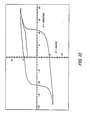
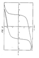
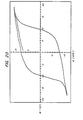
- the measurement was carried out by ramping the field from zero to a maximum (typically 22 kOe), through zero again to a negative maximum, and then back through zero to the positive maximum again, while the entire hysteresis loop was recorded,-(magnetization M vs. applied magnetic field H).
- ribbon samples were measured magnetically along three orthogonal directions: first, in the "x-direction", in the plane of the ribbon parallel to the spin direction (parallel to the length), second, the y-direction, in the plane of the ribbon perpendicular to the spin direction (parallel to the width), and finally in the z-direction, perpendicular to the plane of the ribbon.
- the sample was pre-magnetized in the appropriate direction using the pulsed magnetic field.
- the applied magnetic field necessary to fully saturate these materials should not be underestimated, In particular, once a virgin (unmagnetized) sample has been magnetized in an arbitrary direction, it is often extremely difficult to completely re-magnetize it in another direction. Examples of this magnetic training effect (magnetic training) are discussed below
- Iron-(Neodymium-Praseodymium)-Boron-Silicon The consolidation was carried out by rf induction heating in a quartz crucible. The ingot had the following measured composition.
- composition of a ribbon sample of this series, #400AA03 was measured (by EDS) to be 78.4 at% Fe, 11.0 at% Nd, 2.7 aL% Pr, 1.9 at.% Si, plus a nominal 6% B. This is apparently slightly richer in Si than the ingot alloy.
- Example III - 4 38AA Series -Wheel-speed dependence of magnetic parameters.
- the procedure described above was followed to prepare, quench and test an alloy of Iron-Neodymium-Boron-Silicon.
- the ingot had the measured composition (EDS and WDS) of 79 at% Fe, 11.7 at%Nd, 7.8 at.%B, and 1.6 at% Si. It was prepared by induction heating in a quartz crucible. The applicants had earlier indicated the nominal composition of the elements (which do not include Si) added to the ingot; the silicon comes presumably from partial reaction with the walls of the crucible.
- the quench parameters of these samples were similar to those in Example II above, except that the crucible-wheel distance was 9mm here, and the ribbon dimensions were typically 1.8mm wide by 38-45 microns thick.
- The. material of this example is the material presented as Example I of the co-pending patent application 801,996.
- the composition of the ingot which was rf induction melted in a pyrolytic boron nitride crucible, was measured - (by EDS and WDS -ref. no. 2259) to be Fe 77 . 5 Nd l3 . l Pr 0.8 B 8.0 Si 0.6 where the silicon figure may be comparable to the background level of the measurement
- the quench parameters were similar to those for Example IV above, except that the velocity of the 20" spinner wheel was 800 rpm, and the ribbon dimensions were 1.8mm wide x 38 to 45 microns thick.
- the material of this example is the material presented as Example III of the co-pending patent application 801,996.
- the quench parameters were similar to those for Examples IV and V above, except that the velocity of the 20" spinner wheel was 900 rpm, and the ribbon dimensions were 1.4mm wide x 35 to 48 microns thick.
- the magnetic parameters (pre-magnetized) for some typical ribbon samples measured along the spin direction are as follows:
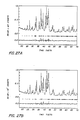
- Powder produced from this set of ribbons was subjected to x-ray diffraction.
- the Rietveld refinements of these powder diffraction plots, before and after refinement for alpha-iron, are shown in Figs. 28A and 28B.
- the refined atomic coordinates for this example are exhibited in summary Table VII.
- the material of this example is the material presented as Example IV of the co-pending patent application 801,996.
- the quench parameters were similar to those for Examples IV and V above, except that the velocity of the 20" spinner wheel was 700 rpm, the orifice diameter was 0.88mm, the crucible discharge pressure was 3.5 psi, and the ribbon dimensions were 1.1mm wide x 33 to 43 microns thick.
- Magnetic parameters (pre-magnetized) for some typical ribbon samples were measured along the spin direction as follows:
- Powder produced from this set of ribbons was subjected to x-ray diffraction.
- the Rietveld reginements of these powder diffraction plots, before and after refinement for afpha-iron, are shown in Figs. 1A and 1B.
- the refined atomic coordinates for this example are exhibited in Table VI earlier, and again in summary Table VII below.
- the ingot of iron, neodymium, boron, and silicon was prepared by induction melting in a quartz crucible following the procedures described above.
- the ingot had an average elemental analysis, in atomic percent by EDS and WDS of:
- the ingots were consolidated by arc melting buttons of alloy in high purity argon (99.98%).
- the starting materials were high quality: Fe 99.99%; Nd 99.9%; B 99.7%; and Si 99.99%.
- Each alloy button was remelted and inverted five times.
- a Zr getter (for oxygen) was used and showed no visible contamination.
- Pieces of the ingot and twins of the magnetically measured melt-spun ribbons had their compositions measured by energy dispersive scanning electron microscopy.
- a "twin” is a fragment broken off next to the bit of magnetically measured ribbon, and is therefore assumed to have essentially the same composition and microstructure.
- melt-spun ribbon is consistently higher in Si content that the ingot.
- the molten alloy acquires this Si from the quartz crucible. This points out the need to measure the composition at each stage of the fabrication.
- the average values of the magnetic properties were obtained from 3 distinct runs wherein each consisted of 10 separate ribbon pieces stacked together. For each measurement the ribbons were magnetically pulsed three times at 120kOe for 1 m sec. The magnetization measurements were performed in a VSM with a maximum applied field of 22kOe.
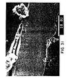
- the fine grain region (located on the wheel side of the melt-spin ribbon) was not resolved by polishing and etching, e.g., in 1 to 2 percent nitric acid in ethanol, but was determined to be less than 2,000 Angstroms. See Figures 30 and 31.
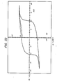
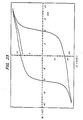
- This fine grain region is identified to be the good magnetic material, i.e., having a high energy product and high remanent magnetization. See the table above and the magnetization curves for 471AC01(3) and 477AA01(5).
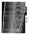
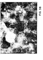
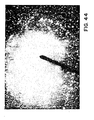
- the SEM photos are the cross sections of the appropriate twins. See Figures 34 and 35.
- the other two samples exhibit a superposition of the good and inferior magnetic material (the latter being identified with the large grain zone found on the free side of the ribbon, see the SEM photos) as shown in the magnetization curves. See Figures 32, 33, 36 and 37.
- the ribbon sample was mounted using standard micro- metallographic techniques, and an ion-beam etcher was used to thin part of the sample down to about one thousand angstroms. Observations were made on the two ribbon surfaces (after argon ion etching away the top half micron), the wheel side and the free side.
- the microstructure on the wheel side consisted primarily of very small equiaxed grains of the main tetragonal phase (with rare-earth to iron ratio consistent with Nd s Fe, ⁇ B), with grain sizes in the range from 100 to 1000 angstroms, that were found by electron diffraction to be randomly oriented. See Figures 38 through 40. There was also a small fraction of grains of alpha-iron, of typical size 500 angstroms or more. On the boundaries between the larger grains of the main tetragonal phase, there was some evidence of an additional phase or phases present as pherical inclusions relatively richer in Neodymium and Sulfur than the main phase. See Figures 41 and 42. Sulfur was not previously believed to be a constituent of the materials. The location of the Si remained difficult to determine.
- Magnetic measurements of the resultant as quenched ribbon showed it to have a low BH max of 1 to 2 megagaussoersteds and a low coercive force of 1 to 3 KOe.
- the magnetic alloy material as quenched is believed to be substantially isotropic.
- Ribbons from the product were wrapped in tantalum foil and sealed under Argon in quartz. After a six hour anneal at 650°C, the following magnetic parameters were obtained using the procedures described above:
- the ingot of iron, praseodymium, neodymium, boron, and silicon was prepared following the procedures described for above.
- the ingot had an average elemental analysis, in atomic percent by EDS and WDS of:
- Sample S715 was produced as described above for cold pressing and adhesive impregnation, using a tungsten carbide die in an hydraulic press and commercially available LOC-TITE (TM) 709 adhesive. Samples S735 was produced by cold pressing without adhesive using a steel die.
- the magnetic properties of the compacted bodies above are normalized to full density of the magnetic alloy material (we have been using the value 7.4 g/cc), they exhibit parameters that are within the range of the as-quenched ribbons of the present invention, e.g. energy product greater than 15 MGOe and remanence greater than 9 kOe.
- the magnetic properties of these compacted bodies are isotropic, so that they also to exhibit values of the magnetic retention parameter greater than 1.0.
- Ribbons spun and quenched from this run had typical magnetic parameters of about 7.8 MGoe for the maximum magnetic energy product and a coercive of about 12 kOe. These were not optimized as-quenched materials.
- the density of this sample was measured by the archimedes technique to be 7.48 gm/cc - (greater than 98% of theoretical x-ray density of 7.6 gm/cc).
- the magnetic properties of this material have not been optimized.
- An appropriately spun material should be chosen so that any influences of heating on the magnetic properties which occur during the consolidation process will cause the performance to be improved.
- the weighted average magnetic energy product of the ribbon was about 15.8 MGOe with a coercive force of about 18.5 kOe.
- the resultant ribbon fragment were then extruded in a polymeric binder in a sheet form.
- the magnetic properties of cube shaped samples were measured. The values reported below are corrected for demagnetization effects and normalized to 100% density of magnetic material.
- the density of magnetic material is the final product was 70 volume %. This example clearly demonstrates that a bonded magnetic may be made from the ribbon of the present invention without loss of properties.
Landscapes
- Engineering & Computer Science (AREA)
- Chemical & Material Sciences (AREA)
- Power Engineering (AREA)
- Crystallography & Structural Chemistry (AREA)
- Inorganic Chemistry (AREA)
- Nanotechnology (AREA)
- Composite Materials (AREA)
- Hard Magnetic Materials (AREA)
- Manufacturing Cores, Coils, And Magnets (AREA)
- Powder Metallurgy (AREA)
- Soft Magnetic Materials (AREA)
Applications Claiming Priority (8)
| Application Number | Priority Date | Filing Date | Title |
|---|---|---|---|
| US70526385A | 1985-02-25 | 1985-02-25 | |
| US70734385A | 1985-02-25 | 1985-02-25 | |
| US705263 | 1985-02-25 | ||
| US707343 | 1985-02-25 | ||
| US80199685A | 1985-11-25 | 1985-11-25 | |
| US801996 | 1985-11-25 | ||
| US81677886A | 1986-01-10 | 1986-01-10 | |
| US816778 | 1986-01-10 |
Publications (4)
| Publication Number | Publication Date |
|---|---|
| EP0195219A2 true EP0195219A2 (de) | 1986-09-24 |
| EP0195219A3 EP0195219A3 (en) | 1987-06-16 |
| EP0195219B1 EP0195219B1 (de) | 1991-04-10 |
| EP0195219B2 EP0195219B2 (de) | 1997-08-20 |
Family
ID=27505491
Family Applications (1)
| Application Number | Title | Priority Date | Filing Date |
|---|---|---|---|
| EP86101510A Expired - Lifetime EP0195219B2 (de) | 1985-02-25 | 1986-02-06 | Abgeschrecktes permanentmagnetisches Material |
Country Status (7)
| Country | Link |
|---|---|
| EP (1) | EP0195219B2 (de) |
| KR (1) | KR860006809A (de) |
| AU (1) | AU578518B2 (de) |
| CA (1) | CA1271394A (de) |
| DE (1) | DE3678596D1 (de) |
| IE (1) | IE57358B1 (de) |
| IN (1) | IN166487B (de) |
Cited By (17)
| Publication number | Priority date | Publication date | Assignee | Title |
|---|---|---|---|---|
| EP0229946A1 (de) * | 1986-01-10 | 1987-07-29 | Ovonic Synthetic Materials Company, Inc. | Permanentmagnetische Legierung |
| EP0260746A1 (de) * | 1986-09-17 | 1988-03-23 | Koninklijke Philips Electronics N.V. | Verfahren zur Herstellung von Spänen aus magnetischem Material mit Vorzugsrichtung der Kristallite, Späne und Magnete, die daraus hergestellt sind |
| US4952251A (en) * | 1989-05-23 | 1990-08-28 | Hitachi Metals, Ltd. | Magnetically anisotropic hotworked magnet and method of producing same |
| US4978398A (en) * | 1988-09-30 | 1990-12-18 | Hitachi Metals, Ltd. | Magnetically anisotropic hot-worked magnet and method of producing same |
| US5026419A (en) * | 1989-05-23 | 1991-06-25 | Hitachi Metals, Ltd. | Magnetically anisotropic hotworked magnet and method of producing same |
| EP0392077A3 (de) * | 1989-04-14 | 1991-06-26 | Hitachi Metals, Ltd. | Heissverformte anisotrope Magnete und deren Herstellung |
| US5098486A (en) * | 1989-05-23 | 1992-03-24 | Hitachi Metals, Ltd. | Magnetically anisotropic hotworked magnet and method of producing same |
| US5403408A (en) * | 1992-10-19 | 1995-04-04 | Inland Steel Company | Non-uniaxial permanent magnet material |
| US5634987A (en) * | 1992-07-16 | 1997-06-03 | The University Of Sheffield | Magnetic materials and method of making them |
| EP0935260A3 (de) * | 1998-02-06 | 1999-12-15 | Toda Kogyo Corp. | Lamellare Partikeln aus Seltenerd-Eisen basierte Legierung,ihrer Herstellungsverfahren und Verbundmagnet daraus |
| EP1017066A3 (de) * | 1998-12-28 | 2000-12-20 | Seiko Epson Corporation | Magnetpulver und isotropen Seltenerdmagneten |
| EP1061533A1 (de) * | 1999-06-11 | 2000-12-20 | Seiko Epson Corporation | Magnetpuder und isotropes Verbundmagnet |
| EP1061532A1 (de) * | 1999-06-11 | 2000-12-20 | Seiko Epson Corporation | Magnetpuder und isotropes Verbundmagnet |
| US6558482B1 (en) | 1999-07-22 | 2003-05-06 | Seiko Epson Corporation | Magnetic powder and isotropic bonded magnet |
| US20150251248A1 (en) * | 2011-09-29 | 2015-09-10 | GM Global Technology Operations LLC | Near Net Shape Manufacturing Of Rare Earth Permanent Magnets |
| CN109887697A (zh) * | 2013-11-05 | 2019-06-14 | 株式会社Ihi | 稀土永磁材料以及稀土永磁材料的制造方法 |
| CN112992458A (zh) * | 2021-02-05 | 2021-06-18 | 北京工业大学 | 一种Pr-Fe-(C,B)稀土永磁材料及其制备方法 |
Families Citing this family (1)
| Publication number | Priority date | Publication date | Assignee | Title |
|---|---|---|---|---|
| US6979409B2 (en) | 2003-02-06 | 2005-12-27 | Magnequench, Inc. | Highly quenchable Fe-based rare earth materials for ferrite replacement |
Family Cites Families (4)
| Publication number | Priority date | Publication date | Assignee | Title |
|---|---|---|---|---|
| CA1316375C (en) * | 1982-08-21 | 1993-04-20 | Masato Sagawa | Magnetic materials and permanent magnets |
| DE3379131D1 (en) * | 1982-09-03 | 1989-03-09 | Gen Motors Corp | Re-tm-b alloys, method for their production and permanent magnets containing such alloys |
| EP0124655B1 (de) * | 1983-05-06 | 1989-09-20 | Sumitomo Special Metals Co., Ltd. | Isotrope permanente Magnete und Verfahren zu ihrer Herstellung |
| AU573895B2 (en) * | 1984-09-17 | 1988-06-23 | Ovonic Synthetic Materials Company, Inc. | Hard magnetic material |
-
1986
- 1986-02-04 CA CA000501015A patent/CA1271394A/en not_active Expired - Lifetime
- 1986-02-06 EP EP86101510A patent/EP0195219B2/de not_active Expired - Lifetime
- 1986-02-06 DE DE8686101510T patent/DE3678596D1/de not_active Expired - Lifetime
- 1986-02-11 IN IN116/DEL/86A patent/IN166487B/en unknown
- 1986-02-21 AU AU53874/86A patent/AU578518B2/en not_active Ceased
- 1986-02-24 IE IE486/86A patent/IE57358B1/en not_active IP Right Cessation
- 1986-02-25 KR KR1019860001302A patent/KR860006809A/ko not_active Ceased
Cited By (23)
| Publication number | Priority date | Publication date | Assignee | Title |
|---|---|---|---|---|
| EP0229946A1 (de) * | 1986-01-10 | 1987-07-29 | Ovonic Synthetic Materials Company, Inc. | Permanentmagnetische Legierung |
| EP0260746A1 (de) * | 1986-09-17 | 1988-03-23 | Koninklijke Philips Electronics N.V. | Verfahren zur Herstellung von Spänen aus magnetischem Material mit Vorzugsrichtung der Kristallite, Späne und Magnete, die daraus hergestellt sind |
| US4978398A (en) * | 1988-09-30 | 1990-12-18 | Hitachi Metals, Ltd. | Magnetically anisotropic hot-worked magnet and method of producing same |
| EP0392077A3 (de) * | 1989-04-14 | 1991-06-26 | Hitachi Metals, Ltd. | Heissverformte anisotrope Magnete und deren Herstellung |
| US4952251A (en) * | 1989-05-23 | 1990-08-28 | Hitachi Metals, Ltd. | Magnetically anisotropic hotworked magnet and method of producing same |
| US5026419A (en) * | 1989-05-23 | 1991-06-25 | Hitachi Metals, Ltd. | Magnetically anisotropic hotworked magnet and method of producing same |
| US5098486A (en) * | 1989-05-23 | 1992-03-24 | Hitachi Metals, Ltd. | Magnetically anisotropic hotworked magnet and method of producing same |
| US5634987A (en) * | 1992-07-16 | 1997-06-03 | The University Of Sheffield | Magnetic materials and method of making them |
| US5403408A (en) * | 1992-10-19 | 1995-04-04 | Inland Steel Company | Non-uniaxial permanent magnet material |
| US6494968B1 (en) | 1998-02-06 | 2002-12-17 | Toda Kogyo Corporation | Lamellar rare earth-iron-boron-based magnet alloy particles, process for producing the same and bonded magnet produced therefrom |
| EP0935260A3 (de) * | 1998-02-06 | 1999-12-15 | Toda Kogyo Corp. | Lamellare Partikeln aus Seltenerd-Eisen basierte Legierung,ihrer Herstellungsverfahren und Verbundmagnet daraus |
| EP1017066A3 (de) * | 1998-12-28 | 2000-12-20 | Seiko Epson Corporation | Magnetpulver und isotropen Seltenerdmagneten |
| US6503415B1 (en) | 1998-12-28 | 2003-01-07 | Seiko Epson Corporation | Magnet powders and isotropic rare-earth bonded magnets |
| EP1061532A1 (de) * | 1999-06-11 | 2000-12-20 | Seiko Epson Corporation | Magnetpuder und isotropes Verbundmagnet |
| EP1061533A1 (de) * | 1999-06-11 | 2000-12-20 | Seiko Epson Corporation | Magnetpuder und isotropes Verbundmagnet |
| US6500277B1 (en) | 1999-06-11 | 2002-12-31 | Seiko Epson Corporation | Magnetic powder and isotropic bonded magnet |
| US6852246B2 (en) | 1999-06-11 | 2005-02-08 | Seiko Epson Corporation | Magnetic powder and isotropic bonded magnet |
| US6558482B1 (en) | 1999-07-22 | 2003-05-06 | Seiko Epson Corporation | Magnetic powder and isotropic bonded magnet |
| US7087185B2 (en) | 1999-07-22 | 2006-08-08 | Seiko Epson Corporation | Magnetic powder and isotropic bonded magnet |
| US20150251248A1 (en) * | 2011-09-29 | 2015-09-10 | GM Global Technology Operations LLC | Near Net Shape Manufacturing Of Rare Earth Permanent Magnets |
| US9272332B2 (en) * | 2011-09-29 | 2016-03-01 | GM Global Technology Operations LLC | Near net shape manufacturing of rare earth permanent magnets |
| CN109887697A (zh) * | 2013-11-05 | 2019-06-14 | 株式会社Ihi | 稀土永磁材料以及稀土永磁材料的制造方法 |
| CN112992458A (zh) * | 2021-02-05 | 2021-06-18 | 北京工业大学 | 一种Pr-Fe-(C,B)稀土永磁材料及其制备方法 |
Also Published As
| Publication number | Publication date |
|---|---|
| DE3678596D1 (de) | 1991-05-16 |
| KR860006809A (ko) | 1986-09-15 |
| EP0195219A3 (en) | 1987-06-16 |
| IN166487B (de) | 1990-05-19 |
| AU578518B2 (en) | 1988-10-27 |
| IE860486L (en) | 1986-08-25 |
| EP0195219B1 (de) | 1991-04-10 |
| CA1271394A (en) | 1990-07-10 |
| EP0195219B2 (de) | 1997-08-20 |
| IE57358B1 (en) | 1992-08-12 |
| AU5387486A (en) | 1986-08-28 |
Similar Documents
| Publication | Publication Date | Title |
|---|---|---|
| EP0195219B1 (de) | Abgeschrecktes permanentmagnetisches Material | |
| KR960008185B1 (ko) | 희토류-철계 영구자석 및 이의 제조방법 | |
| US4867785A (en) | Method of forming alloy particulates having controlled submicron crystallite size distributions | |
| EP0411571B1 (de) | Seltenerdpulver für Dauermagnet, Herstellungsverfahren und Verbundmagnet | |
| Ormerod | The physical metallurgy and processing of sintered rare earth permanent magnets | |
| Saito et al. | The development of high performance Nd–Fe–Co–Ga–B die upset magnets | |
| EP0249973B1 (de) | Dauermagnet-Material und Verfahren zur Herstellung | |
| CN103180917A (zh) | 稀土-铁-氮系合金材料及其制备方法、稀土-铁系合金材料及其制备方法 | |
| JP2003226944A (ja) | 希土類−鉄−硼素系磁石用合金粉末を用いた焼結磁石 | |
| JPS62276803A (ja) | 希土類−鉄系永久磁石 | |
| Hirosawa et al. | New aspects of Nd–Fe–B-based hydrogenation-disproportionation-desorption-recombination powders and anisotropic bonded magnets made from them: Microstructure and magnetic properties | |
| Liu et al. | Compositional optimization and new processes for nanocrystalline NdFeB-based permanent magnets | |
| Aich et al. | Rapidly solidified rare-earth permanent magnets: processing, properties, and applications | |
| Cook et al. | Rare-earth iron boron supermagnets | |
| EP0229946B1 (de) | Permanentmagnetische Legierung | |
| WO1990008593A1 (en) | Method and apparatus for making polycrystaline flakes of magnetic materials having strong grain orientation | |
| JPH1154353A (ja) | R−t−b系永久磁石の焼結方法 | |
| JP3645312B2 (ja) | 磁性材料と製造法 | |
| JP3209291B2 (ja) | 磁性材料とその製造方法 | |
| Koper et al. | Improving the Properties of Permanent Magnets: A Study of Patents, Patent Applications and Other Literature | |
| JPH06124812A (ja) | 窒化物磁性粉とその合成方法 | |
| JPH06112019A (ja) | 窒化物磁性材料 | |
| JP3209292B2 (ja) | 磁性材料とその製造方法 | |
| JPS61243154A (ja) | 磁性合金 | |
| JPH05152119A (ja) | 熱間加工した希土類元素−鉄−炭素磁石 |
Legal Events
| Date | Code | Title | Description |
|---|---|---|---|
| PUAI | Public reference made under article 153(3) epc to a published international application that has entered the european phase |
Free format text: ORIGINAL CODE: 0009012 |
|
| AK | Designated contracting states |
Kind code of ref document: A2 Designated state(s): CH DE FR GB IT LI NL SE |
|
| 17P | Request for examination filed |
Effective date: 19861111 |
|
| PUAL | Search report despatched |
Free format text: ORIGINAL CODE: 0009013 |
|
| RAP1 | Party data changed (applicant data changed or rights of an application transferred) |
Owner name: OVONIC SYNTHETIC MATERIALS COMPANY, INC. |
|
| AK | Designated contracting states |
Kind code of ref document: A3 Designated state(s): CH DE FR GB IT LI NL SE |
|
| 17Q | First examination report despatched |
Effective date: 19890223 |
|
| ITF | It: translation for a ep patent filed | ||
| GRAA | (expected) grant |
Free format text: ORIGINAL CODE: 0009210 |
|
| AK | Designated contracting states |
Kind code of ref document: B1 Designated state(s): CH DE FR GB IT LI NL SE |
|
| REF | Corresponds to: |
Ref document number: 3678596 Country of ref document: DE Date of ref document: 19910516 |
|
| ET | Fr: translation filed | ||
| PLBI | Opposition filed |
Free format text: ORIGINAL CODE: 0009260 |
|
| 26 | Opposition filed |
Opponent name: TDK CORPORATION Effective date: 19920110 |
|
| NLR1 | Nl: opposition has been filed with the epo |
Opponent name: TDK CORPORATION |
|
| PLAB | Opposition data, opponent's data or that of the opponent's representative modified |
Free format text: ORIGINAL CODE: 0009299OPPO |
|
| R26 | Opposition filed (corrected) |
Opponent name: TDK CORPORATION Effective date: 19920110 |
|
| PGFP | Annual fee paid to national office [announced via postgrant information from national office to epo] |
Ref country code: CH Payment date: 19940330 Year of fee payment: 9 |
|
| EAL | Se: european patent in force in sweden |
Ref document number: 86101510.5 |
|
| PG25 | Lapsed in a contracting state [announced via postgrant information from national office to epo] |
Ref country code: LI Effective date: 19950228 Ref country code: CH Effective date: 19950228 |
|
| PGFP | Annual fee paid to national office [announced via postgrant information from national office to epo] |
Ref country code: SE Payment date: 19960215 Year of fee payment: 11 |
|
| PLAW | Interlocutory decision in opposition |
Free format text: ORIGINAL CODE: EPIDOS IDOP |
|
| PLAW | Interlocutory decision in opposition |
Free format text: ORIGINAL CODE: EPIDOS IDOP |
|
| PG25 | Lapsed in a contracting state [announced via postgrant information from national office to epo] |
Ref country code: SE Effective date: 19970207 |
|
| PUAH | Patent maintained in amended form |
Free format text: ORIGINAL CODE: 0009272 |
|
| STAA | Information on the status of an ep patent application or granted ep patent |
Free format text: STATUS: PATENT MAINTAINED AS AMENDED |
|
| 27A | Patent maintained in amended form |
Effective date: 19970820 |
|
| AK | Designated contracting states |
Kind code of ref document: B2 Designated state(s): CH DE FR GB IT LI NL SE |
|
| REG | Reference to a national code |
Ref country code: CH Ref legal event code: AEN Free format text: MAINTIEN DU BREVET DONT L'ETENDUE A ETE MODIFIEE |
|
| NLR2 | Nl: decision of opposition | ||
| NLR3 | Nl: receipt of modified translations in the netherlands language after an opposition procedure | ||
| EUG | Se: european patent has lapsed |
Ref document number: 86101510.5 |
|
| ET3 | Fr: translation filed ** decision concerning opposition | ||
| ET2 | Fr: translation filed ** revision of the translation of the modified patent after opposition | ||
| ET3 | Fr: translation filed ** decision concerning opposition | ||
| REG | Reference to a national code |
Ref country code: GB Ref legal event code: IF02 |
|
| PGFP | Annual fee paid to national office [announced via postgrant information from national office to epo] |
Ref country code: NL Payment date: 20050110 Year of fee payment: 20 Ref country code: GB Payment date: 20050110 Year of fee payment: 20 |
|
| PGFP | Annual fee paid to national office [announced via postgrant information from national office to epo] |
Ref country code: FR Payment date: 20050202 Year of fee payment: 20 |
|
| PG25 | Lapsed in a contracting state [announced via postgrant information from national office to epo] |
Ref country code: IT Free format text: LAPSE BECAUSE OF NON-PAYMENT OF DUE FEES;WARNING: LAPSES OF ITALIAN PATENTS WITH EFFECTIVE DATE BEFORE 2007 MAY HAVE OCCURRED AT ANY TIME BEFORE 2007. THE CORRECT EFFECTIVE DATE MAY BE DIFFERENT FROM THE ONE RECORDED. Effective date: 20050206 |
|
| PGFP | Annual fee paid to national office [announced via postgrant information from national office to epo] |
Ref country code: DE Payment date: 20050228 Year of fee payment: 20 |
|
| PG25 | Lapsed in a contracting state [announced via postgrant information from national office to epo] |
Ref country code: GB Free format text: LAPSE BECAUSE OF EXPIRATION OF PROTECTION Effective date: 20060205 |
|
| PG25 | Lapsed in a contracting state [announced via postgrant information from national office to epo] |
Ref country code: NL Free format text: LAPSE BECAUSE OF EXPIRATION OF PROTECTION Effective date: 20060206 |
|
| REG | Reference to a national code |
Ref country code: GB Ref legal event code: PE20 |
|
| NLV7 | Nl: ceased due to reaching the maximum lifetime of a patent |
Effective date: 20060206 |
|
| PLAB | Opposition data, opponent's data or that of the opponent's representative modified |
Free format text: ORIGINAL CODE: 0009299OPPO |