EP0196019A2 - Rollenrotations-Offsetdruckmaschine mit einem Druckwerk für fliegenden Plattenwechsel - Google Patents
Rollenrotations-Offsetdruckmaschine mit einem Druckwerk für fliegenden Plattenwechsel Download PDFInfo
- Publication number
- EP0196019A2 EP0196019A2 EP86103809A EP86103809A EP0196019A2 EP 0196019 A2 EP0196019 A2 EP 0196019A2 EP 86103809 A EP86103809 A EP 86103809A EP 86103809 A EP86103809 A EP 86103809A EP 0196019 A2 EP0196019 A2 EP 0196019A2
- Authority
- EP
- European Patent Office
- Prior art keywords
- cylinder
- drive
- printing unit
- printing
- blanket
- Prior art date
- Legal status (The legal status is an assumption and is not a legal conclusion. Google has not performed a legal analysis and makes no representation as to the accuracy of the status listed.)
- Granted
Links
Images

Classifications
-
- B—PERFORMING OPERATIONS; TRANSPORTING
- B41—PRINTING; LINING MACHINES; TYPEWRITERS; STAMPS
- B41F—PRINTING MACHINES OR PRESSES
- B41F7/00—Rotary lithographic machines
- B41F7/02—Rotary lithographic machines for offset printing
- B41F7/12—Rotary lithographic machines for offset printing using two cylinders one of which serves two functions, e.g. as a transfer and impression cylinder in perfecting machines
Definitions
- the invention relates to a web-fed offset printing press with a plurality of printing units arranged one behind the other, in each of which a printing material web can be coated on both sides with ink, and a printing unit for flying plate changes, in which one plate cylinder and blanket cylinder pair are stopped for the plate change and the other is employed on a common rotating impression cylinder can be.
- an offset rotary printing press in which a plurality of printing units are arranged one behind the other, wherein a printing material web in each of the printing units can be coated with a color on both sides.
- the first printing unit a so-called single-printing unit, comprises a double large common impression cylinder, to which a pair of blanket-plate cylinders is attached, while the other pair of blanket-plate cylinders can be prepared for the plate change.
- This known printing machine has the disadvantage that a separate printing unit is required for the single-printing unit with a flying plate change.
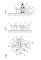
- Fig. 1 shows the cylinder arrangement of the first printing unit in a web offset rotary printing press which has a plurality of printing units for face and back printing, which are arranged one behind the other.
- the printing unit shown comprises a first pair of cylinders, consisting of a plate cylinder 1 and a blanket cylinder 2, and a second pair of cylinders, consisting of a plate cylinder 3 and a blanket cylinder 4.
- a printing material web 5 between the blanket cylinders 2 and 4 is usually printed on both sides, ie provided with a perfecting.
- the main drive for the cylinders 1 to 4 is fed in the printing unit in the printing unit from a gear 7, a bevel gear 6 which, like the other gears used, is preferably helically toothed.
- the gear wheel 7 is seated on a shaft 8 (FIG. 3) on which two clutches 9, 10 are also arranged.
- the shaft 8 is aligned with the axis of a common impression cylinder 11 for the blanket cylinders 2, 4 or is identical to this.
- Two gearwheels 11 ′, 11 ′′ are arranged on the shaft 8, and can optionally be fixedly connected to the drive shaft 8 by means of the couplings 9, 10.
- FIG. 2 shows the drive wheel train of the cylinders 1 to 4 on one side of the machine.
- the drive is advantageously initiated from the main drive by actuating the clutch 9 in such a way that the bevel gear 6 drives the gear 11 '.
- the gear 11 ' meshes with the gear 2' on the axis of the rubber blanket cylinder 2.
- This gear 2 'arranged on the axis of the rubber blanket cylinder then directs the drive directly to the meshing drive wheel 1' of the plate cylinder 1 and the meshing gear 4 'of the blanket cylinder 4.
- the double-wide gear 3' of the plate cylinder 3 also meshes with the gear 4 ', so that the cylinders 1 to 4 can be driven by the main drive in the straight printing reverse printing operation shown in Fig.1.
- the drive thus takes place according to FIG. 1 from B to A1 and A2 to A3.
- the impression cylinder 11 serves as a paper guide roller for the web 5 to be printed during normal perfecting and counter-printing operations. In this operating mode, it is also possible to slightly turn off the impression cylinder 11 serving as the paper guide roller from the blanket cylinder 2. It is separated from the blanket cylinder 4 anyway. Conventional conventional eccentrics, which are indicated in FIGS. 1 and 4 but not described in more detail, can be used for this. The impression cylinder 11 is also separated from the blanket cylinder 4.
- the printing unit in addition to the operating mode shown in FIG. 1, can also be used as a single-printing unit with a flying plate change.
- This is indicated schematically in Figure 4.
- the print carrier web 5 is not passed between the two blanket cylinders 2 and 4, but rather around the impression cylinder 11.
- the main drive is introduced via the impression cylinder 11 or via the gearwheels 11 'or 11' 'arranged on it.
- bevel gear 6, i.e. from the main drive 7, 8 only the gears 2 ', 1' and thus the cylinders 2 and 1 or the gears 11 '', 4 'and 3' and thus the cylinders 4 and 3 are driven.
- the non-driven plate cylinder 1 or 3 with the associated Gurnmituch cylinder can be stopped for a plate change.
- the cylinder for example 1, is accelerated from the auxiliary drive 12 via a bevel gear 14, a clutch 16 and a further bevel gear 18 to the speed of the main drive and is synchronized with it.
- the coupling 15 separates the auxiliary drive 12 from the lower plate cylinder 3.
- a corresponding conventional electronic circuit ensures that the auxiliary drive 12 is connected to the plate cylinder 1 or the plate cylinder 3 either after corresponding preparatory work.
- the cylinders 1 and 2 can then be connected to the impression cylinder 11, i.e. the blanket cylinder 2 is turned on the impression cylinder 1 by actuating the eccentric.
- the main drive 6, 7 is separated from the cylinder pair 3 and 4 and in turn the gear 4 'is displaced and, after a corresponding plate change on the plate cylinder 3, the auxiliary drive via a bevel gear 13 of the clutch 15 and a bevel gear 17 of the plate cylinder 3 and thus the blanket cylinder 4 is accelerated and synchronized to the operating speed, after which the adjustment to the impression cylinder 11 takes place in the same way.
- the drive takes place via B1 and C2 or B2 and Cl.
- a profile shift is carried out in the drive gearwheels used. As indicated in FIGS. 2, 3 and 5, a negative profile shift is carried out on the gears 1 1 , 4 ', 11' in the manner according to the invention, while a positive profile shift is carried out on the gears 2 '', 2 ', 11''and3' Profile shift is made.
Landscapes
- Engineering & Computer Science (AREA)
- Mechanical Engineering (AREA)
- Inking, Control Or Cleaning Of Printing Machines (AREA)
- Rotary Presses (AREA)
Abstract
Description
- Die Erfindung betrifft eine Rollenrotation-Offsetdruckmaschine mit mehreren hintereinander angeordneten Druckwerken, in denen jeweils eine Bedruckstoffbahn beidseitig mit Farbe belegt werden kann und einem Druckwerk für fliegenden Plattenwechsel, in dem ein Plattenzylinder-Gummituchzylinderpaar für den Plattenwechsel stillgesetzt und das andere an einen gemeinsamen rotierenden Gegendruckzylinder angestellt werden kann.
- Aus dem auf der DRUPA 1982 verteilten Prospekt "Albert A101" der Firma Albert Frankenthal ist eine Offsetrotationsdruckmaschine bekannt, bei der mehrere Druckwerke hintereinander angeordnet sind, wobei eine Bedruckstoffbahn in jedem der Druckwerke beidseitig mit einer Farbe belegt werden kann. Das erste Druckwerk, ein sogenanntes Ein-Druckwerk, umfaßt einen doppelt großen gemeinsamen Gegendruckzylinder, an den jeweils ein Gummituch-Plattenzylinderpaar angestellt ist, während das andere Gummituch-Plattenzylinderpaar für den Plattenwechsel vorbereitet werden kann. Diese bekannte Druckmaschine weist den Nachteil auf, daß für das Ein-Druckwerk mit fliegendem Plattenwechsel ein gesondertes Druckwerk benötigt wird.
- Aufgabe der Erfindung ist es, mindestens ein Druckwerk einer Rollenrotations-Offsetdruckmaschine mit mehreren Schön- und Widerdruckwerken so zu verbessern, daß in diesem Druckwerk sowohl in herkömmlicher Weise nach dem Schön- und Widerdruckprinzip gearbeitet, als auch dieses Druckwerk als Ein-Druckwerk mit fliegendem Plattenwechsel verwendbar ist und daß der Antriebsräderzug an einer Seite der Maschine angeordnet werden kann. Diese Aufgabe wird durch die Anwendung der Merkmale des kennzeichnenden Teils des Anspruchs 1 gelöst. Vorteilhafte Weiterbildungen ergeben sich aus den Unteransprüchen und aus der Beschreibung in Verbindung mit den Zeichnungen. In diesen zeigen:
- Fig.l das Zylinderschema des erfindungsgemäßen Druckwerkes im Schön- und Widerdruckbetrieb,
- Fig.2 und 3 den Antriebsräderzug für die Betriebsweise gemäß Fig.l,
- Fig.4 das erfindungsgemäße Druckwerk als Ein-Druckwerk mit fliegendem Plattenwechsel und
- Fig.5 den Antriebsräderzug für die Betriebsweise gemäß Fig.4.
- Fig. 1 zeigt die Zylinderanordnung des ersten Druckwerkes in einer Rollenoffset-Rotationsdruckmaschine, die mehrere Druckwerke für Schön- und Widerdruck aufweist, die hintereinander angeordnet sind. Das dargestellte Druckwerk umfaßt ein erstes Zylinderpaar, bestehend aus einem Plattenzylinder 1 und einem Gummituchzylinder 2, und ein zweites Zylinderpaar, bestehend aus einem Plattenzylinder 3 und einem Gummituchzylinder 4. In solchen Druckwerken wird üblicherweise eine Bedruckstoffbahn 5 zwischen den Gummituchzylindern 2 und 4 beidseitig bedruckt, d.h. mit einem Schön- und Widerdruck versehen.
- In erfindungsgemäßer Weise wird in dem Druckwerk bei der vorangehend erwähnten Betriebsweise der Hauptantrieb für die Zylinder 1 bis 4 von einem Zahnrad 7, einem Kegelrad 6, das wie die übrigen verwendeten Zahnräder vorzugsweise schräg verzahnt ist, zugeleitet. Das Zahnrad 7 sitzt auf einer Welle 8 (Fig.3), auf der des weiteren zwei Kupplungen 9, 10 angeordnet sind. Die Welle 8 fluchtet mit der Achse eines gemeinsamen Gegendruckzylinders 11 für die Gummituchzylinder 2, 4 oder ist mit dieser identisch. Auf der Welle 8 sind zwei Zahnräder 11', 11" angeordnet, die mittels der Kupplungen 9, 10 wahlweise fest mit der Antriebswelle 8 verbindbar sind. Fig.2 zeigt den Antriebsräderzug der Zylinder 1 bis 4 an einer Maschinenseite. Eingeleitet wird in vorteilhafter Weise vom Hauptantrieb her der Antrieb durch Betätigung der Kupplung 9 in der Weise, daß vom Kegelrad 6 das Zahnrad 11' angetrieben wird. Das Zahnrad 11' kämmt mit dem Zahnrad 2' auf der Achse des Gummituchzylinders 2. Dieses auf der Achse des Gummituchzylinders angeordnete Zahnrad 2' leitet dann den Antrieb direkt auf das mit ihm kämmende Antriebsrad 1' des Plattenzylinders 1 und das mit ihm kämmende Zahnrad 4' des Gummituchzylinders 4. Das doppelt breite Zahnrad 3' des Plattenzylinders 3 kämmt ebenfalls mit dem Zahnrad 4', so daß die Zylinder 1 bis 4 bei dem in Fig.1 dargestellten Schöndruck-Widerdruckbetrieb vom Hauptantrieb her antreibbar sind. Der Antrieb erfolgt also gemäß Fig.1 von B zu A1 und A2 nach A3.
- In vorteilhafter Weise dient der Gegendruckzylinder 11 beim normalen Schön- und Widerdruckbetrieb für die zu bedruckende Bahn 5 als Papierleitwalze. Bei dieser Betriebsart ist es auch möglich, den als Papierleitwalze dienenden Gegendruckzylinder 11 von dem Gummituchzylinder 2 geringfügig abzustellen. Von dem Gummituchzylinder 4 ist er ohnehin getrennt. Hierfür können übliche, in den Figuren 1 und 4 angedeutete aber nicht näher bezeichnete herkömmliche Stellexzenter verwendet werden. Von dem Gummituchzylinder 4 ist der Gegendruckzylinder 11 ebenfalls getrennt.
- Gemäß der Erfindung kann neben der in Fig.1 dargestellten Betriebsart das Druckwerk auch als Ein-Druckwerk mit fliegendem Plattenwechsel eingesetzt werden. Dies ist in Fig.4 schematisch angedeutet. Hierfür wird die Druckträgerbahn 5 nicht zwischen den beiden Gummituchzylindern 2 und 4, sondern um den Gegendruckzylinder 11 teilweise herumgeführt. Auch bei dieser Betriebsweise wird der Hauptantrieb über den Gegendruckzylinder 11 bzw. über die auf ihm angeordneten Zahnräder 11' oder 11'' eingeleitet. Je nachdem, ob die oberen Zylinder 1 und 2 stillgesetzt werden sollen, um am Plattenzylinder 1 einen Plattenwechsel vornehmen zu können oder ob dies bei den unteren Zylindern 3, 4 erfolgen soll, wird mit Hilfe der Kupplungen 9 und 10 entweder das Zahnrad 11' oder das Zahnrad 11'' von der Antriebswelle 8 gelöst. Somit werden entweder vom Kegelrad 6, d.h. vom Hauptantrieb 7, 8 her nur die Zahnräder 2', 1' und somit die Zylinder 2 und 1 oder die Zahnräder 11'', 4' und 3' und somit die Zylinder 4 und 3 angetrieben.
- Lediglich das Zahnrad 4' muß verschoben werden, wie in Fig. 2, 4 angedeutet ist. Der jeweils nicht angetriebene Plattenzylinder 1 oder 3 mit dem zugehörigen Gurnmituchzylinder kann für einen Plattenwechsel stillgesetzt werden. Nach erfolgtem Plattenwechsel wird der Zylinder, beispielsweise 1, von dem Hilfsantrieb 12 her über ein Kegelrad 14, eine Kupplung 16 und ein weiteres Kegelrad 18 auf die Drehzahl des Hauptantriebes beschleunigt und mit diesem synchronisiert. In diesem Fall trennt die Kupplung 15 den Hilfsantrieb 12 vom unteren Plattenzylinder 3. Durch eine entsprechende herkömmliche elektronische Schaltung ist sichergestellt, daß der Hilfsantrieb 12 entweder nach entsprechenden Vorbereitungsarbeiten mit dem Plattenzylinder 1 oder dem Plattenzylinder 3 verbunden wird. Nach erfolgter Beschleunigung und Synchronisierung über den Hilfsantrieb 12 können dann die Zylinder 1 und 2 mit dem Gegendruckzylinder 11 in Verbindung gebracht werden, d.h. der Gummituchzylinder 2 wird durch Betätigung der Stellexzenter an den Gegendruckzylinder 1 angestellt.
- Im umgekehrten Fall wird durch Betätigung der Kupplung 10 der Hauptantrieb 6, 7 von dem Zylinderpaar 3 und 4 getrennt und wiederum das Zahnrad 4' verschoben und nach entsprechendem Plattenwechsel am Plattenzylinder 3 der Hilfsantrieb über ein Kegelrad 13 der Kupplung 15 und ein Kegelrad 17 der Plattenzylinder 3 und somit der Gummituchzylinder 4 auf die Betriebsdrehzahl beschleunigt und synchronisiert, wonach in der gleichen Weise die Anstellung an den Gegendruckzylinder 11 erfolgt. Gemäß Fig.2 erfolgt der Antrieb über B1 und C2 oder B2 und Cl.
- Für das erfindungsgemäße Druckwerk ist es wesentlich, daß bei den verwendeten Antriebszahnrädern eine Profilverschiebung vorgenommen wird. Wie in den Figuren 2, 3 und 5 angedeutet, wird in erfindungsgemäßer Weise an den Zahnrädern 11, 4', 11' eine negative Profilverschiebung vorgenommen, während an den Zahnrädern 2'', 2', 11''und 3' eine positive Profilverschiebung vorgenommen wird.
Claims (4)
daß in dem Druckwerk beim Schöndruck-Widerdruckbetrieb ein Gegendruckzylinder (11) als Papierleitwalze für die zwischen den Gummituchzylindern (2, 4) geführte Bahn (5) verwendet wird,
daß auf der Achse (8) des Gegendruckzylinders (11) zwei Zahnräder (11', 11'') positioniert sind, die über Kupplungen (9, 10) den Hauptantrieb B (6, 7, 8) wahlweise mit einem oder beiden Gummituchzylinder-Antriebsrädern (2', 4') verbinden,
daß ein Gummituchzylinder-Antriebsrad (4') mit einem doppelt breiten Plattenzylinder-Antriebsrad (3') kämmt und axial verschiebbar ist, und daß im Ein-Druckbetrieb (fliegender Plattenwechsel) der Antrieb (1', 2') jeweils eines Plattenzylinder-Gummituchzylinderpaares (1, 2) von dem über den Gegendruckzylinder (11) zugeleiteten Hauptantrieb (6, 7, 8) abgekuppelt wird (A1 oder A2).
Applications Claiming Priority (2)
| Application Number | Priority Date | Filing Date | Title |
|---|---|---|---|
| DE3510823 | 1985-03-26 | ||
| DE3510823A DE3510823C1 (de) | 1985-03-26 | 1985-03-26 | Rollenrotations-Offsetdruckmaschine mit einem Druckwerk fuer fliegenden Plattenwechsel |
Publications (3)
| Publication Number | Publication Date |
|---|---|
| EP0196019A2 true EP0196019A2 (de) | 1986-10-01 |
| EP0196019A3 EP0196019A3 (en) | 1987-06-16 |
| EP0196019B1 EP0196019B1 (de) | 1989-12-13 |
Family
ID=6266299
Family Applications (1)
| Application Number | Title | Priority Date | Filing Date |
|---|---|---|---|
| EP86103809A Expired EP0196019B1 (de) | 1985-03-26 | 1986-03-20 | Rollenrotations-Offsetdruckmaschine mit einem Druckwerk für fliegenden Plattenwechsel |
Country Status (3)
| Country | Link |
|---|---|
| EP (1) | EP0196019B1 (de) |
| JP (1) | JPS61273957A (de) |
| DE (2) | DE3510823C1 (de) |
Cited By (4)
| Publication number | Priority date | Publication date | Assignee | Title |
|---|---|---|---|---|
| GB2205070A (en) * | 1986-12-24 | 1988-11-30 | Roland Man Druckmasch | Connection and registration of printing units |
| EP0612614A1 (de) * | 1993-02-22 | 1994-08-31 | Heidelberger Druckmaschinen Aktiengesellschaft | Rollen-Rotationsdruckmaschine mit Eindruckwerk für fliegenden Druckformwechsel |
| EP0826494A1 (de) * | 1996-08-28 | 1998-03-04 | KOENIG & BAUER-ALBERT AKTIENGESELLSCHAFT | Druckeinheit |
| WO2002024453A1 (de) * | 2000-09-20 | 2002-03-28 | Koenig & Bauer Aktiengesellschaft | Druckeinheiten mit antriebsverbund und kupplung |
Families Citing this family (4)
| Publication number | Priority date | Publication date | Assignee | Title |
|---|---|---|---|---|
| DE3510823C1 (de) | 1985-03-26 | 1986-09-11 | Roland Man Druckmasch | Rollenrotations-Offsetdruckmaschine mit einem Druckwerk fuer fliegenden Plattenwechsel |
| DE3614029C1 (de) * | 1986-04-25 | 1987-04-02 | Roland Man Druckmasch | Rollenrotations-Offsetdruckmaschine mit einem Druckwerk fuer fliegenden Plattenwechsel |
| DE3825145A1 (de) * | 1988-07-23 | 1990-01-25 | Koenig & Bauer Ag | Rollenrotations-offsetdruckmaschine mit einem druckwerk fuer fliegenden plattenwechsel |
| DE19853114B4 (de) * | 1998-11-18 | 2010-01-28 | Manroland Ag | Doppeldruckwerk einer Rotationsdruckmaschine |
Family Cites Families (8)
| Publication number | Priority date | Publication date | Assignee | Title |
|---|---|---|---|---|
| US3329086A (en) * | 1966-06-14 | 1967-07-04 | Miehle Goss Dexter Inc | Perfecting or multicolor offset printing press |
| JPS5114922A (en) * | 1974-07-29 | 1976-02-05 | Taketoshi Yano | Kawarano seizohoho oyobi sonosochi |
| DE2844418C3 (de) * | 1978-10-12 | 1982-02-11 | Albert-Frankenthal Ag, 6710 Frankenthal | Rollen-Rotationsdruckmaschine mit einer Einrichtung zum Herstellen von Druckerzeugnissen mit wechselnden Eindrucken |
| SE426153B (sv) * | 1979-01-22 | 1982-12-13 | Wifag Maschf | Drivanordning for en valsrotations offsettryckmaskin |
| US4240346A (en) * | 1979-01-29 | 1980-12-23 | Harris Corporation | Web printing press |
| JPS55103959A (en) * | 1979-02-02 | 1980-08-08 | Tokyo Kikai Seisakusho:Kk | Printing mode selector for printing drum of rotary press |
| JPS56111669A (en) * | 1980-02-06 | 1981-09-03 | Tokyo Kikai Seisakusho:Kk | Printing mode switching device in blanket drum of offset rotary printing press |
| DE3510823C1 (de) | 1985-03-26 | 1986-09-11 | Roland Man Druckmasch | Rollenrotations-Offsetdruckmaschine mit einem Druckwerk fuer fliegenden Plattenwechsel |
-
1985
- 1985-03-26 DE DE3510823A patent/DE3510823C1/de not_active Expired
-
1986
- 1986-03-20 EP EP86103809A patent/EP0196019B1/de not_active Expired
- 1986-03-20 DE DE8686103809T patent/DE3667426D1/de not_active Expired - Lifetime
- 1986-03-25 JP JP61065038A patent/JPS61273957A/ja active Pending
Cited By (7)
| Publication number | Priority date | Publication date | Assignee | Title |
|---|---|---|---|---|
| GB2205070A (en) * | 1986-12-24 | 1988-11-30 | Roland Man Druckmasch | Connection and registration of printing units |
| GB2205070B (en) * | 1986-12-24 | 1991-01-30 | Roland Man Druckmasch | A rotary printing machine with selectively connectible printing units |
| EP0612614A1 (de) * | 1993-02-22 | 1994-08-31 | Heidelberger Druckmaschinen Aktiengesellschaft | Rollen-Rotationsdruckmaschine mit Eindruckwerk für fliegenden Druckformwechsel |
| US5381734A (en) * | 1993-02-22 | 1995-01-17 | Heidelberger Druckmaschinen Ag | Web-fed rotary printing press with imprinting unit for flying printing-form exchange |
| EP0826494A1 (de) * | 1996-08-28 | 1998-03-04 | KOENIG & BAUER-ALBERT AKTIENGESELLSCHAFT | Druckeinheit |
| WO2002024453A1 (de) * | 2000-09-20 | 2002-03-28 | Koenig & Bauer Aktiengesellschaft | Druckeinheiten mit antriebsverbund und kupplung |
| US6827011B2 (en) | 2000-09-20 | 2004-12-07 | Koenig & Bauer Aktiengesellschaft | Printers comprising a drive assembly and a coupling |
Also Published As
| Publication number | Publication date |
|---|---|
| DE3667426D1 (de) | 1990-01-18 |
| DE3510823C1 (de) | 1986-09-11 |
| EP0196019B1 (de) | 1989-12-13 |
| EP0196019A3 (en) | 1987-06-16 |
| JPS61273957A (ja) | 1986-12-04 |
Similar Documents
| Publication | Publication Date | Title |
|---|---|---|
| EP0919372B1 (de) | Druckwerk für eine Rotationsdruckmaschine | |
| DE4430693B4 (de) | Antriebe für eine Rollenrotations-Offsetdruckmaschine | |
| EP0154836B1 (de) | Registerstellvorrichtung für eine Rotationsdruckmaschine | |
| EP0997273B1 (de) | Druckwerk einer Rollenrotations-Druckmaschine | |
| DE3432572A1 (de) | Rotationsdruckpresse | |
| EP1155825A2 (de) | Druckwerksanordnung in einer Rollenrotationsdruckmaschine | |
| DE2844418C3 (de) | Rollen-Rotationsdruckmaschine mit einer Einrichtung zum Herstellen von Druckerzeugnissen mit wechselnden Eindrucken | |
| EP0243721B1 (de) | Rollenrotations-Offsetdruckmaschine mit einem Druckwerk für fliegenden Plattenwechsel | |
| EP0286982A2 (de) | Registerstellvorrichtung | |
| EP0352483A2 (de) | Flexodruckmaschine | |
| DE3045611C2 (de) | Registerstelleinrichtung einer Bogen-Rotationsoffsetdruckmaschine für gleichzeitigen Schön- und Widerdruck | |
| DE2753433C2 (de) | Verfahren und Vorrichtung zum Voreinstellen der Formzylinder von Mehrfarbenrollen-Rotationsdruckmaschinen | |
| EP0401656A2 (de) | Vorrichtung zum Einstellen des Seiten- und Umfangsregisters in einer Rotationsdruckmaschine | |
| EP0196019B1 (de) | Rollenrotations-Offsetdruckmaschine mit einem Druckwerk für fliegenden Plattenwechsel | |
| DE3510822C1 (de) | Rollenrotations-Offsetdruckmaschine mit fliegendem Plattenwechsel | |
| DE3922559C2 (de) | Offsetdruckwerk | |
| DE3805209C2 (de) | ||
| EP0705689B1 (de) | Antrieb für eine Mehrfarbenbogendruckmaschine | |
| DE3832891A1 (de) | Offset-druckmaschine zum drucken einer kontinuierlichen bahn | |
| DE3644445C2 (de) | ||
| DE2553768C3 (de) | Rollen-Rotationsdruckmaschine | |
| EP0498012A1 (de) | Flexodruckmaschine mit Wechselspur-Hilfszahnrad | |
| CH686426A5 (de) | Druckpresse mit aneinander anstellbaren Drucktuchzylindern. | |
| DE234969C (de) | ||
| DE10206891A1 (de) | Druckwerksantrieb |
Legal Events
| Date | Code | Title | Description |
|---|---|---|---|
| PUAI | Public reference made under article 153(3) epc to a published international application that has entered the european phase |
Free format text: ORIGINAL CODE: 0009012 |
|
| AK | Designated contracting states |
Kind code of ref document: A2 Designated state(s): CH DE FR GB IT LI SE |
|
| PUAL | Search report despatched |
Free format text: ORIGINAL CODE: 0009013 |
|
| AK | Designated contracting states |
Kind code of ref document: A3 Designated state(s): CH DE FR GB IT LI SE |
|
| 17P | Request for examination filed |
Effective date: 19870519 |
|
| 17Q | First examination report despatched |
Effective date: 19881108 |
|
| ITF | It: translation for a ep patent filed | ||
| GRAA | (expected) grant |
Free format text: ORIGINAL CODE: 0009210 |
|
| AK | Designated contracting states |
Kind code of ref document: B1 Designated state(s): CH DE FR GB IT LI SE |
|
| REF | Corresponds to: |
Ref document number: 3667426 Country of ref document: DE Date of ref document: 19900118 |
|
| GBT | Gb: translation of ep patent filed (gb section 77(6)(a)/1977) | ||
| ET | Fr: translation filed | ||
| PLBE | No opposition filed within time limit |
Free format text: ORIGINAL CODE: 0009261 |
|
| STAA | Information on the status of an ep patent application or granted ep patent |
Free format text: STATUS: NO OPPOSITION FILED WITHIN TIME LIMIT |
|
| 26N | No opposition filed | ||
| PGFP | Annual fee paid to national office [announced via postgrant information from national office to epo] |
Ref country code: SE Payment date: 19930222 Year of fee payment: 8 |
|
| ITTA | It: last paid annual fee | ||
| PG25 | Lapsed in a contracting state [announced via postgrant information from national office to epo] |
Ref country code: SE Free format text: LAPSE BECAUSE OF NON-PAYMENT OF DUE FEES Effective date: 19940321 |
|
| EUG | Se: european patent has lapsed |
Ref document number: 86103809.9 Effective date: 19941010 |
|
| PGFP | Annual fee paid to national office [announced via postgrant information from national office to epo] |
Ref country code: GB Payment date: 19960215 Year of fee payment: 11 |
|
| PGFP | Annual fee paid to national office [announced via postgrant information from national office to epo] |
Ref country code: FR Payment date: 19960220 Year of fee payment: 11 Ref country code: CH Payment date: 19960220 Year of fee payment: 11 |
|
| PGFP | Annual fee paid to national office [announced via postgrant information from national office to epo] |
Ref country code: DE Payment date: 19960223 Year of fee payment: 11 |
|
| PG25 | Lapsed in a contracting state [announced via postgrant information from national office to epo] |
Ref country code: GB Effective date: 19970320 |
|
| PG25 | Lapsed in a contracting state [announced via postgrant information from national office to epo] |
Ref country code: LI Effective date: 19970331 Ref country code: CH Effective date: 19970331 |
|
| GBPC | Gb: european patent ceased through non-payment of renewal fee |
Effective date: 19970320 |
|
| REG | Reference to a national code |
Ref country code: CH Ref legal event code: PL |
|
| PG25 | Lapsed in a contracting state [announced via postgrant information from national office to epo] |
Ref country code: FR Free format text: LAPSE BECAUSE OF NON-PAYMENT OF DUE FEES Effective date: 19971128 |
|
| PG25 | Lapsed in a contracting state [announced via postgrant information from national office to epo] |
Ref country code: DE Effective date: 19971202 |
|
| REG | Reference to a national code |
Ref country code: FR Ref legal event code: ST |
|
| PG25 | Lapsed in a contracting state [announced via postgrant information from national office to epo] |
Ref country code: IT Free format text: LAPSE BECAUSE OF NON-PAYMENT OF DUE FEES;WARNING: LAPSES OF ITALIAN PATENTS WITH EFFECTIVE DATE BEFORE 2007 MAY HAVE OCCURRED AT ANY TIME BEFORE 2007. THE CORRECT EFFECTIVE DATE MAY BE DIFFERENT FROM THE ONE RECORDED. Effective date: 20050320 |