EP0196019A2 - Machine à imprimer rotative offset à bobines avec un mécanisme d'impression pour changement de plaques volant - Google Patents
Machine à imprimer rotative offset à bobines avec un mécanisme d'impression pour changement de plaques volant Download PDFInfo
- Publication number
- EP0196019A2 EP0196019A2 EP86103809A EP86103809A EP0196019A2 EP 0196019 A2 EP0196019 A2 EP 0196019A2 EP 86103809 A EP86103809 A EP 86103809A EP 86103809 A EP86103809 A EP 86103809A EP 0196019 A2 EP0196019 A2 EP 0196019A2
- Authority
- EP
- European Patent Office
- Prior art keywords
- cylinder
- drive
- printing unit
- printing
- blanket
- Prior art date
- Legal status (The legal status is an assumption and is not a legal conclusion. Google has not performed a legal analysis and makes no representation as to the accuracy of the status listed.)
- Granted
Links
Images

Classifications
-
- B—PERFORMING OPERATIONS; TRANSPORTING
- B41—PRINTING; LINING MACHINES; TYPEWRITERS; STAMPS
- B41F—PRINTING MACHINES OR PRESSES
- B41F7/00—Rotary lithographic machines
- B41F7/02—Rotary lithographic machines for offset printing
- B41F7/12—Rotary lithographic machines for offset printing using two cylinders one of which serves two functions, e.g. as a transfer and impression cylinder in perfecting machines
Definitions
- the invention relates to a web-fed offset printing press with a plurality of printing units arranged one behind the other, in each of which a printing material web can be coated on both sides with ink, and a printing unit for flying plate changes, in which one plate cylinder and blanket cylinder pair are stopped for the plate change and the other is employed on a common rotating impression cylinder can be.
- an offset rotary printing press in which a plurality of printing units are arranged one behind the other, wherein a printing material web in each of the printing units can be coated with a color on both sides.
- the first printing unit a so-called single-printing unit, comprises a double large common impression cylinder, to which a pair of blanket-plate cylinders is attached, while the other pair of blanket-plate cylinders can be prepared for the plate change.
- This known printing machine has the disadvantage that a separate printing unit is required for the single-printing unit with a flying plate change.
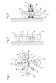
- Fig. 1 shows the cylinder arrangement of the first printing unit in a web offset rotary printing press which has a plurality of printing units for face and back printing, which are arranged one behind the other.
- the printing unit shown comprises a first pair of cylinders, consisting of a plate cylinder 1 and a blanket cylinder 2, and a second pair of cylinders, consisting of a plate cylinder 3 and a blanket cylinder 4.
- a printing material web 5 between the blanket cylinders 2 and 4 is usually printed on both sides, ie provided with a perfecting.
- the main drive for the cylinders 1 to 4 is fed in the printing unit in the printing unit from a gear 7, a bevel gear 6 which, like the other gears used, is preferably helically toothed.
- the gear wheel 7 is seated on a shaft 8 (FIG. 3) on which two clutches 9, 10 are also arranged.
- the shaft 8 is aligned with the axis of a common impression cylinder 11 for the blanket cylinders 2, 4 or is identical to this.
- Two gearwheels 11 ′, 11 ′′ are arranged on the shaft 8, and can optionally be fixedly connected to the drive shaft 8 by means of the couplings 9, 10.
- FIG. 2 shows the drive wheel train of the cylinders 1 to 4 on one side of the machine.
- the drive is advantageously initiated from the main drive by actuating the clutch 9 in such a way that the bevel gear 6 drives the gear 11 '.
- the gear 11 ' meshes with the gear 2' on the axis of the rubber blanket cylinder 2.
- This gear 2 'arranged on the axis of the rubber blanket cylinder then directs the drive directly to the meshing drive wheel 1' of the plate cylinder 1 and the meshing gear 4 'of the blanket cylinder 4.
- the double-wide gear 3' of the plate cylinder 3 also meshes with the gear 4 ', so that the cylinders 1 to 4 can be driven by the main drive in the straight printing reverse printing operation shown in Fig.1.
- the drive thus takes place according to FIG. 1 from B to A1 and A2 to A3.
- the impression cylinder 11 serves as a paper guide roller for the web 5 to be printed during normal perfecting and counter-printing operations. In this operating mode, it is also possible to slightly turn off the impression cylinder 11 serving as the paper guide roller from the blanket cylinder 2. It is separated from the blanket cylinder 4 anyway. Conventional conventional eccentrics, which are indicated in FIGS. 1 and 4 but not described in more detail, can be used for this. The impression cylinder 11 is also separated from the blanket cylinder 4.
- the printing unit in addition to the operating mode shown in FIG. 1, can also be used as a single-printing unit with a flying plate change.
- This is indicated schematically in Figure 4.
- the print carrier web 5 is not passed between the two blanket cylinders 2 and 4, but rather around the impression cylinder 11.
- the main drive is introduced via the impression cylinder 11 or via the gearwheels 11 'or 11' 'arranged on it.
- bevel gear 6, i.e. from the main drive 7, 8 only the gears 2 ', 1' and thus the cylinders 2 and 1 or the gears 11 '', 4 'and 3' and thus the cylinders 4 and 3 are driven.
- the non-driven plate cylinder 1 or 3 with the associated Gurnmituch cylinder can be stopped for a plate change.
- the cylinder for example 1, is accelerated from the auxiliary drive 12 via a bevel gear 14, a clutch 16 and a further bevel gear 18 to the speed of the main drive and is synchronized with it.
- the coupling 15 separates the auxiliary drive 12 from the lower plate cylinder 3.
- a corresponding conventional electronic circuit ensures that the auxiliary drive 12 is connected to the plate cylinder 1 or the plate cylinder 3 either after corresponding preparatory work.
- the cylinders 1 and 2 can then be connected to the impression cylinder 11, i.e. the blanket cylinder 2 is turned on the impression cylinder 1 by actuating the eccentric.
- the main drive 6, 7 is separated from the cylinder pair 3 and 4 and in turn the gear 4 'is displaced and, after a corresponding plate change on the plate cylinder 3, the auxiliary drive via a bevel gear 13 of the clutch 15 and a bevel gear 17 of the plate cylinder 3 and thus the blanket cylinder 4 is accelerated and synchronized to the operating speed, after which the adjustment to the impression cylinder 11 takes place in the same way.
- the drive takes place via B1 and C2 or B2 and Cl.
- a profile shift is carried out in the drive gearwheels used. As indicated in FIGS. 2, 3 and 5, a negative profile shift is carried out on the gears 1 1 , 4 ', 11' in the manner according to the invention, while a positive profile shift is carried out on the gears 2 '', 2 ', 11''and3' Profile shift is made.
Landscapes
- Engineering & Computer Science (AREA)
- Mechanical Engineering (AREA)
- Inking, Control Or Cleaning Of Printing Machines (AREA)
- Rotary Presses (AREA)
Applications Claiming Priority (2)
| Application Number | Priority Date | Filing Date | Title |
|---|---|---|---|
| DE3510823 | 1985-03-26 | ||
| DE3510823A DE3510823C1 (de) | 1985-03-26 | 1985-03-26 | Rollenrotations-Offsetdruckmaschine mit einem Druckwerk fuer fliegenden Plattenwechsel |
Publications (3)
| Publication Number | Publication Date |
|---|---|
| EP0196019A2 true EP0196019A2 (fr) | 1986-10-01 |
| EP0196019A3 EP0196019A3 (en) | 1987-06-16 |
| EP0196019B1 EP0196019B1 (fr) | 1989-12-13 |
Family
ID=6266299
Family Applications (1)
| Application Number | Title | Priority Date | Filing Date |
|---|---|---|---|
| EP86103809A Expired EP0196019B1 (fr) | 1985-03-26 | 1986-03-20 | Machine à imprimer rotative offset à bobines avec un mécanisme d'impression pour changement de plaques volant |
Country Status (3)
| Country | Link |
|---|---|
| EP (1) | EP0196019B1 (fr) |
| JP (1) | JPS61273957A (fr) |
| DE (2) | DE3510823C1 (fr) |
Cited By (4)
| Publication number | Priority date | Publication date | Assignee | Title |
|---|---|---|---|---|
| GB2205070A (en) * | 1986-12-24 | 1988-11-30 | Roland Man Druckmasch | Connection and registration of printing units |
| EP0612614A1 (fr) * | 1993-02-22 | 1994-08-31 | Heidelberger Druckmaschinen Aktiengesellschaft | Machine à imprimer rotative offset à bobines avec un mécanisme d'impression volant pour changement de plaques |
| EP0826494A1 (fr) * | 1996-08-28 | 1998-03-04 | KOENIG & BAUER-ALBERT AKTIENGESELLSCHAFT | Unité d'impression |
| WO2002024453A1 (fr) * | 2000-09-20 | 2002-03-28 | Koenig & Bauer Aktiengesellschaft | Unites d'impression a ensemble d'entrainement et accouplement |
Families Citing this family (4)
| Publication number | Priority date | Publication date | Assignee | Title |
|---|---|---|---|---|
| DE3510823C1 (de) | 1985-03-26 | 1986-09-11 | Roland Man Druckmasch | Rollenrotations-Offsetdruckmaschine mit einem Druckwerk fuer fliegenden Plattenwechsel |
| DE3614029C1 (de) * | 1986-04-25 | 1987-04-02 | Roland Man Druckmasch | Rollenrotations-Offsetdruckmaschine mit einem Druckwerk fuer fliegenden Plattenwechsel |
| DE3825145A1 (de) * | 1988-07-23 | 1990-01-25 | Koenig & Bauer Ag | Rollenrotations-offsetdruckmaschine mit einem druckwerk fuer fliegenden plattenwechsel |
| DE19853114B4 (de) * | 1998-11-18 | 2010-01-28 | Manroland Ag | Doppeldruckwerk einer Rotationsdruckmaschine |
Family Cites Families (8)
| Publication number | Priority date | Publication date | Assignee | Title |
|---|---|---|---|---|
| US3329086A (en) * | 1966-06-14 | 1967-07-04 | Miehle Goss Dexter Inc | Perfecting or multicolor offset printing press |
| JPS5114922A (en) * | 1974-07-29 | 1976-02-05 | Taketoshi Yano | Kawarano seizohoho oyobi sonosochi |
| DE2844418C3 (de) * | 1978-10-12 | 1982-02-11 | Albert-Frankenthal Ag, 6710 Frankenthal | Rollen-Rotationsdruckmaschine mit einer Einrichtung zum Herstellen von Druckerzeugnissen mit wechselnden Eindrucken |
| SE426153B (sv) * | 1979-01-22 | 1982-12-13 | Wifag Maschf | Drivanordning for en valsrotations offsettryckmaskin |
| US4240346A (en) * | 1979-01-29 | 1980-12-23 | Harris Corporation | Web printing press |
| JPS55103959A (en) * | 1979-02-02 | 1980-08-08 | Tokyo Kikai Seisakusho:Kk | Printing mode selector for printing drum of rotary press |
| JPS56111669A (en) * | 1980-02-06 | 1981-09-03 | Tokyo Kikai Seisakusho:Kk | Printing mode switching device in blanket drum of offset rotary printing press |
| DE3510823C1 (de) | 1985-03-26 | 1986-09-11 | Roland Man Druckmasch | Rollenrotations-Offsetdruckmaschine mit einem Druckwerk fuer fliegenden Plattenwechsel |
-
1985
- 1985-03-26 DE DE3510823A patent/DE3510823C1/de not_active Expired
-
1986
- 1986-03-20 EP EP86103809A patent/EP0196019B1/fr not_active Expired
- 1986-03-20 DE DE8686103809T patent/DE3667426D1/de not_active Expired - Lifetime
- 1986-03-25 JP JP61065038A patent/JPS61273957A/ja active Pending
Cited By (7)
| Publication number | Priority date | Publication date | Assignee | Title |
|---|---|---|---|---|
| GB2205070A (en) * | 1986-12-24 | 1988-11-30 | Roland Man Druckmasch | Connection and registration of printing units |
| GB2205070B (en) * | 1986-12-24 | 1991-01-30 | Roland Man Druckmasch | A rotary printing machine with selectively connectible printing units |
| EP0612614A1 (fr) * | 1993-02-22 | 1994-08-31 | Heidelberger Druckmaschinen Aktiengesellschaft | Machine à imprimer rotative offset à bobines avec un mécanisme d'impression volant pour changement de plaques |
| US5381734A (en) * | 1993-02-22 | 1995-01-17 | Heidelberger Druckmaschinen Ag | Web-fed rotary printing press with imprinting unit for flying printing-form exchange |
| EP0826494A1 (fr) * | 1996-08-28 | 1998-03-04 | KOENIG & BAUER-ALBERT AKTIENGESELLSCHAFT | Unité d'impression |
| WO2002024453A1 (fr) * | 2000-09-20 | 2002-03-28 | Koenig & Bauer Aktiengesellschaft | Unites d'impression a ensemble d'entrainement et accouplement |
| US6827011B2 (en) | 2000-09-20 | 2004-12-07 | Koenig & Bauer Aktiengesellschaft | Printers comprising a drive assembly and a coupling |
Also Published As
| Publication number | Publication date |
|---|---|
| DE3667426D1 (de) | 1990-01-18 |
| DE3510823C1 (de) | 1986-09-11 |
| EP0196019B1 (fr) | 1989-12-13 |
| EP0196019A3 (en) | 1987-06-16 |
| JPS61273957A (ja) | 1986-12-04 |
Similar Documents
| Publication | Publication Date | Title |
|---|---|---|
| EP0919372B1 (fr) | Groupe imprimant pour une rotative | |
| DE4430693B4 (de) | Antriebe für eine Rollenrotations-Offsetdruckmaschine | |
| EP0154836B1 (fr) | Dispositif de répérage pour rotatives d'impression | |
| EP0997273B1 (fr) | Groupe imprimant d'une presse à bobines | |
| DE3432572A1 (de) | Rotationsdruckpresse | |
| EP1155825A2 (fr) | Arrengement des groupes imprimants dans une presse rotative pour bandes | |
| DE2844418C3 (de) | Rollen-Rotationsdruckmaschine mit einer Einrichtung zum Herstellen von Druckerzeugnissen mit wechselnden Eindrucken | |
| EP0243721B1 (fr) | Rotative offset avec une unité d'impression pour le changement de plaques en marche | |
| EP0286982A2 (fr) | Dispositif de mise en registre | |
| EP0352483A2 (fr) | Machine d'impression flexographique | |
| DE3045611C2 (de) | Registerstelleinrichtung einer Bogen-Rotationsoffsetdruckmaschine für gleichzeitigen Schön- und Widerdruck | |
| DE2753433C2 (de) | Verfahren und Vorrichtung zum Voreinstellen der Formzylinder von Mehrfarbenrollen-Rotationsdruckmaschinen | |
| EP0401656A2 (fr) | Dispositif pour régler la position latérale et circonférentielle dans une presse à imprimer rotative | |
| EP0196019B1 (fr) | Machine à imprimer rotative offset à bobines avec un mécanisme d'impression pour changement de plaques volant | |
| DE3510822C1 (de) | Rollenrotations-Offsetdruckmaschine mit fliegendem Plattenwechsel | |
| DE3922559C2 (de) | Offsetdruckwerk | |
| DE3805209C2 (fr) | ||
| EP0705689B1 (fr) | Entraînement pour une machine à imprimer des feuilles en plusieurs couleurs | |
| DE3832891A1 (de) | Offset-druckmaschine zum drucken einer kontinuierlichen bahn | |
| DE3644445C2 (fr) | ||
| DE2553768C3 (de) | Rollen-Rotationsdruckmaschine | |
| EP0498012A1 (fr) | Machine d'impression flexographique avec engrenage auxiliaire pour changement de voie d'entraînement | |
| CH686426A5 (de) | Druckpresse mit aneinander anstellbaren Drucktuchzylindern. | |
| DE234969C (fr) | ||
| DE10206891A1 (de) | Druckwerksantrieb |
Legal Events
| Date | Code | Title | Description |
|---|---|---|---|
| PUAI | Public reference made under article 153(3) epc to a published international application that has entered the european phase |
Free format text: ORIGINAL CODE: 0009012 |
|
| AK | Designated contracting states |
Kind code of ref document: A2 Designated state(s): CH DE FR GB IT LI SE |
|
| PUAL | Search report despatched |
Free format text: ORIGINAL CODE: 0009013 |
|
| AK | Designated contracting states |
Kind code of ref document: A3 Designated state(s): CH DE FR GB IT LI SE |
|
| 17P | Request for examination filed |
Effective date: 19870519 |
|
| 17Q | First examination report despatched |
Effective date: 19881108 |
|
| ITF | It: translation for a ep patent filed | ||
| GRAA | (expected) grant |
Free format text: ORIGINAL CODE: 0009210 |
|
| AK | Designated contracting states |
Kind code of ref document: B1 Designated state(s): CH DE FR GB IT LI SE |
|
| REF | Corresponds to: |
Ref document number: 3667426 Country of ref document: DE Date of ref document: 19900118 |
|
| GBT | Gb: translation of ep patent filed (gb section 77(6)(a)/1977) | ||
| ET | Fr: translation filed | ||
| PLBE | No opposition filed within time limit |
Free format text: ORIGINAL CODE: 0009261 |
|
| STAA | Information on the status of an ep patent application or granted ep patent |
Free format text: STATUS: NO OPPOSITION FILED WITHIN TIME LIMIT |
|
| 26N | No opposition filed | ||
| PGFP | Annual fee paid to national office [announced via postgrant information from national office to epo] |
Ref country code: SE Payment date: 19930222 Year of fee payment: 8 |
|
| ITTA | It: last paid annual fee | ||
| PG25 | Lapsed in a contracting state [announced via postgrant information from national office to epo] |
Ref country code: SE Free format text: LAPSE BECAUSE OF NON-PAYMENT OF DUE FEES Effective date: 19940321 |
|
| EUG | Se: european patent has lapsed |
Ref document number: 86103809.9 Effective date: 19941010 |
|
| PGFP | Annual fee paid to national office [announced via postgrant information from national office to epo] |
Ref country code: GB Payment date: 19960215 Year of fee payment: 11 |
|
| PGFP | Annual fee paid to national office [announced via postgrant information from national office to epo] |
Ref country code: FR Payment date: 19960220 Year of fee payment: 11 Ref country code: CH Payment date: 19960220 Year of fee payment: 11 |
|
| PGFP | Annual fee paid to national office [announced via postgrant information from national office to epo] |
Ref country code: DE Payment date: 19960223 Year of fee payment: 11 |
|
| PG25 | Lapsed in a contracting state [announced via postgrant information from national office to epo] |
Ref country code: GB Effective date: 19970320 |
|
| PG25 | Lapsed in a contracting state [announced via postgrant information from national office to epo] |
Ref country code: LI Effective date: 19970331 Ref country code: CH Effective date: 19970331 |
|
| GBPC | Gb: european patent ceased through non-payment of renewal fee |
Effective date: 19970320 |
|
| REG | Reference to a national code |
Ref country code: CH Ref legal event code: PL |
|
| PG25 | Lapsed in a contracting state [announced via postgrant information from national office to epo] |
Ref country code: FR Free format text: LAPSE BECAUSE OF NON-PAYMENT OF DUE FEES Effective date: 19971128 |
|
| PG25 | Lapsed in a contracting state [announced via postgrant information from national office to epo] |
Ref country code: DE Effective date: 19971202 |
|
| REG | Reference to a national code |
Ref country code: FR Ref legal event code: ST |
|
| PG25 | Lapsed in a contracting state [announced via postgrant information from national office to epo] |
Ref country code: IT Free format text: LAPSE BECAUSE OF NON-PAYMENT OF DUE FEES;WARNING: LAPSES OF ITALIAN PATENTS WITH EFFECTIVE DATE BEFORE 2007 MAY HAVE OCCURRED AT ANY TIME BEFORE 2007. THE CORRECT EFFECTIVE DATE MAY BE DIFFERENT FROM THE ONE RECORDED. Effective date: 20050320 |