EP0196094B1 - Système de transmission d'informations à plusieurs éléments - Google Patents
Système de transmission d'informations à plusieurs éléments Download PDFInfo
- Publication number
- EP0196094B1 EP0196094B1 EP86104186A EP86104186A EP0196094B1 EP 0196094 B1 EP0196094 B1 EP 0196094B1 EP 86104186 A EP86104186 A EP 86104186A EP 86104186 A EP86104186 A EP 86104186A EP 0196094 B1 EP0196094 B1 EP 0196094B1
- Authority
- EP
- European Patent Office
- Prior art keywords
- information
- signal
- transmission
- priority
- transmitted
- Prior art date
- Legal status (The legal status is an assumption and is not a legal conclusion. Google has not performed a legal analysis and makes no representation as to the accuracy of the status listed.)
- Expired - Lifetime
Links
- 230000005540 biological transmission Effects 0.000 title claims description 185
- 238000000034 method Methods 0.000 description 8
- 238000004891 communication Methods 0.000 description 7
- 238000010586 diagram Methods 0.000 description 7
- 238000012544 monitoring process Methods 0.000 description 6
- 230000006870 function Effects 0.000 description 5
- 230000004044 response Effects 0.000 description 4
- 230000008054 signal transmission Effects 0.000 description 3
- 238000012546 transfer Methods 0.000 description 3
- 230000005856 abnormality Effects 0.000 description 2
- 238000010276 construction Methods 0.000 description 2
- 238000007796 conventional method Methods 0.000 description 1
- 230000010485 coping Effects 0.000 description 1
- 230000001419 dependent effect Effects 0.000 description 1
- 230000000694 effects Effects 0.000 description 1
- 238000012423 maintenance Methods 0.000 description 1
- 230000001737 promoting effect Effects 0.000 description 1
- 238000004092 self-diagnosis Methods 0.000 description 1
- 238000004904 shortening Methods 0.000 description 1
- 230000001360 synchronised effect Effects 0.000 description 1
Images


Classifications
-
- H—ELECTRICITY
- H04—ELECTRIC COMMUNICATION TECHNIQUE
- H04L—TRANSMISSION OF DIGITAL INFORMATION, e.g. TELEGRAPHIC COMMUNICATION
- H04L12/00—Data switching networks
- H04L12/28—Data switching networks characterised by path configuration, e.g. LAN [Local Area Networks] or WAN [Wide Area Networks]
- H04L12/42—Loop networks
- H04L12/423—Loop networks with centralised control, e.g. polling
-
- G—PHYSICS
- G08—SIGNALLING
- G08C—TRANSMISSION SYSTEMS FOR MEASURED VALUES, CONTROL OR SIMILAR SIGNALS
- G08C15/00—Arrangements characterised by the use of multiplexing for the transmission of a plurality of signals over a common path
- G08C15/06—Arrangements characterised by the use of multiplexing for the transmission of a plurality of signals over a common path successively, i.e. using time division
- G08C15/12—Arrangements characterised by the use of multiplexing for the transmission of a plurality of signals over a common path successively, i.e. using time division the signals being represented by pulse characteristics in transmission link
-
- H—ELECTRICITY
- H04—ELECTRIC COMMUNICATION TECHNIQUE
- H04Q—SELECTING
- H04Q9/00—Arrangements in telecontrol or telemetry systems for selectively calling a substation from a main station, in which substation desired apparatus is selected for applying a control signal thereto or for obtaining measured values therefrom
- H04Q9/14—Calling by using pulses
Definitions
- This invention relates to multi-element information transmission systems and more particularly to a multi-element information transmission system suitable for inputting a multi-element information signal string including plural kinds of information signals such as video signals of television cameras, process signals and status signals of control units and transmitting specified one and/or ones of these signals with priority.
- JP-A-56-111345 discloses an information priority transmission system representative of a technique directed to the above transmission system for plants.
- a transmission frame consisting of a sync word, a station number word and an item word is prepared in a particular station and this frame signal is transmitted to different stations.
- the item word herein referred to consists of various data items.
- the particular station prepares a transmission frame consisting of a sync word, a priority transmission flag, a station number word and a priority transmission word, and this frame signal is transmitted to different stations.
- the priority transmission flag herein referred to indicates that a specified data is being transmitted with priority.
- the particular station selects the data subject to priority transmission from the item word to be transmitted during the normal transmission and reconstructs the priority transmission word by assembling the selected data in a single item word.
- the priority transmission word is prepared by the particular station and transmitted with priority during the priority transmission.
- a particular terminal also prepares an information piece of its own to be transmitted with priority and transmits the information piece, with the result that the aforementioned problems are encountered.
- the conventional techniques have unapplicability to the data transmission in plants wherein a great amount of data from a great number of terminals are to be transmitted.
- An object of this invention is to provide a multi-element information transmission system for such transmission of various signals from a plurality of slave stations to a master station as in a plant, which can transmit, as necessary, a specified signal with priority at a short period under synchronization settled between the slave stations.
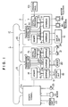
- Fig. 1 shows a multi-element information transmission system according to an embodiment of the invention exemplarily constructed as a transmission system of loop type wherein a central controller serving as a master station is connected toga plurality of remote terminals S1, ----, S n serving as slave stations through a loop transmission path 1.
- the multi-element information transmission system is adapted for transmission of a multi-element information signal in which information signals obtained from a plurality of different information generating sources are assembled.
- the information signal of multi-element information is exemplified at sections (a) and (b) in Fig. 4.
- Each of the remote terminals S1, ----, S n is connected with industrial television camera or cameras (ITV cameras) for monitoring states of apparatus of a plant, sensors for measuring status parameters (temperature, pressure, flow rate and the like) of the plant, and plant apparatus control units for controlling apparatus such as for example valves, pumps and motors of the plant.
- the ITV cameras are designated by reference numerals 21, 24 and 25, the sensors by 20 and 23, and the plant apparatus control units by 19 and 22.
- the ITV cameras 21, 24 and 25 monitor apparatus to be monitored and produce video signals representative of pieces of monitoring information concerning the apparatus.
- the sensors 20 and 23 produce information signals representative of status parameters of controllable apparatus of the plant.
- the signals from the sensors 20 and 23 may be fetched by the control units 19 and 22, respectively.
- each of the remote terminals S1, ----, S n is constructed as will be explained below by way of example of the remote terminal S1.
- the remote terminal S has a transmission control unit 13, a memory 14, a central processor 15, and interfaces 16 to 18.
- the transmission control unit 13, memory 14, central processor 15 and interfaces 16 to 18 are coupled together through a bus 50 serving as a signal transmission channel in the remote terminal S.
- the remote terminal S is connected to the control controller 2 by way of the transmission control unit 13 connected to the loop transmission path 1.
- the central processor 15 of the remote terminal S collectively controls the remote terminal S. Signals produced from the ITV cameras 21, 24 and 25 are fetched into the remote terminal S by means of the video interface 18. Signals from the sensor 20 are fetched into the remote terminal S by means of the process signal fetching interface 17.
- the plant apparatus control unit 19 provides a status parameter of its own which is such information on maintenance as results of self-diagnosis, and the information is fetched into the remote terminal S through the status information fetching interface 16. Pieces of the information fetched into the remote terminal S through the respective interfaces are sent to the loop transmission path 1 by means of the transmission control unit 13 controlled by the central processor 15, so as to be transmitted to the central controller 2.
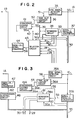
- the transmission control unit 13 has a sync signal detector circuit 35, a time slot counter circuit 36, a serial/parallel converter 37, a separator circuit 38, a coincidence judging circuit 41, a selector circuit 43, and a parallel/serial converter 44.
- the coincidence judging circuit 41 is adapted to decide a time for commencement of transmission of a priority information signal.
- a portion 1A of loop transmission path 1 on the input side of the remote terminal S is connected to the sync signal detector circuit 35.
- the time slot counter circuit 36 and serial/parallel converter 37 are also connected to the loop transmission path portion 1A.
- a portion 1B of loop transmission path 1 on the output side of the remote terminal S is connected to the parallel/serial converter 44.
- the output of the sync signal detector circuit 35 is connected to the time slot counter circuit 36 via a line 51.
- a line 52 connects the output of the time slot counter circuit 36 to the coincidence judging circuit 41.
- the serial/parallel converter 37 is coupled with the bus 50 and also connected to the separator circuit 38 via a line 53.
- a line 39 coupled with the bus 50 connects to the coincidence judging circuit 41.
- a line 40 coupled to the bus 50 connects to the separator circuit 38 and selector circuit 43.
- a line 42 connected to the output of the coincidence judging circuit 41 also connects to the separator circuit 38 and selector circuit 43.
- Lines 31, 32 and 33 connected to individual output terminals of the separator circuit 38 connect to the separator circuit 43.
- Lines 26, 27 and 28 extending from the selector circuit 43 respectively connect to the interfaces 16, 17 and 18.
- a line 54 connects the output of the selector circuit 43 to the input of the parallel/serial converter 44.
- the central controller 2 functions to fetch and process information signals transmitted from the remote terminals S1, ----, S n and also functions to transmit control signals inclusive of transmission control signals. However, the control signals are herein limited to transmission control signals. As shown in Fig. 1, the central controller 2 has a transmission control unit 5, a central processor 7, a memory 6, a video display interface 9, and a data transfer interface 8. A bus 55 serving as a signal transmission channel in the central controller 2 is coupled to the transmission control unit 5, central processor 7, memory 6 and interfaces 8 and 9. Video signals produced from the ITV cameras connected to the remote terminals are displayed on monitor televisions M1 to M m by way of the video display interface 9. Process information signals produced from the sensors 20 and 23 and signals indicative of states of the control units 19 and 22 are outputted to a display unit 10 by way of the data transfer interface 8.
- the transmission control unit 5 has a sync signal detector circuit 35A, a time slot counter circuit 36a, a serial/parallel converter 37A, a separator circuit 38A, a coincidence judging circuit 41A, a transmission control circuit 46, and a parallel/serial converter 47.
- the sync signal detector circuit 35A, time slot counter circuit 36A, serial/parallel converter 37A and coincidence judging circuit 41A have the same constructions as those of the sync signal detector circuit 35, time slot counter circuit 36, serial/parallel converter 37 and coincidence judging circuit 41 of the remote terminal S, and function in the same way.
- a portion 1C of loop transmission path l on the input side of the central controller 2 is connected to the sync signal detector circuit 35A.
- the loop transmission path portion 1A which is the output as viewed from the central controller 2, is connected to the parallel/serial converter 47.
- the loop transmission path portion 1C is also connected to the time slot counter circuit 36A and serial/parallel converter 37A.
- the output of the sync signal detector circuit 35A is connected to the time slot counter circuit 36A via a line 56.
- Respectively connected to two input terminals of the coincidence judging circuit 41A are lines 57 and 58, the former line extending from the output of the time slot counter circuit 36A and the latter line being coupled with the bus 55.
- the serial/parallel converter 37A is coupled to the bus 55 and also connected to one input terminal of the separator circuit 38A via a line 59.
- the other input terminal of the separator circuit 38A is connected to a line 60 coupled with the bus 55.
- a line 61 connects the output of the coincidence judging circuit 41A to the separator circuit 38A whose output terminals are connected to lines 20 and 30.
- the line 29 connects to the data interface 8 and the line 30 connects to the video display interface 9.
- the transmission control circuit 46 coupled with the bus 55 is connected to the parallel/serial converter 47 via a line 62.
- an information signal string which contains in an orderly manner, as exemplified at section (a) in Fig. 4, video signals I1 I2, I3, ----, I i produced from the ITV cameras connected to the respective remote terminals S (video signals outputted from different ITV cameras are suffixed differently) and data signals P produced from the sensors and control units connected to the respective remote terminals S.
- the video signals outputted from two ITV cameras can be transmitted simultaneously in one frame.
- a sync signal SYN for synchronization of the information transmission signal string is exemplarily allotted to the zero-th time slot.
- Each bit is constituted by the same number of bits (for example, 8 bits).
- Signals from the sensors 20 and 23 and control units 19 and 22 constituting the data signals P are allotted to the time slots (3n + 3) in a manner, for example, as shown in Fig. 5.
- the video signal I1 corresponds to an output signal from the ITV camera 21, the video signal I2 to an output signal from an ITV camera not shown which is connected to the video interface 18, the video signal I3 to an output signal from the ITV camera 24, and the video signal I4 to an output signal from the ITV camera 25.
- Video signals represented by I5 and I with the ensuing suffix correspond to output signals from ITV cameras, not shown, connected to the remote terminal S n . It is noted that analog video signals produced from the ITV cameras are sampled at a predetermined period so as to be converted into digital video signals which are allotted to the time slots of the information transmission signal string.
- one picture frame on screen imaged by one ITV camera is formed by all of the digital video signals allotted to the n time slots 1, 4, 7, 10, ----, (3n + 1).
- another picture frame imaged by another ITV camera is formed by all of the digital video signals allotted to the n time slots 2, 5, 8, 11, ----, (3n + 2).
- priority transmission of, for example, the video signal produced from the ITV camera 24 connected to the remote terminal S1 is carried out as will be described below.
- the central controller 2 first transmits to each of the remote terminals S an information transmission signal string in which, as shown at section (b) in Fig. 4, a priority change information signal C is assigned to, for example, the area of a time slot at time T1 normally designated by the data signal P.
- a code violation code which is different from the transmission code for the other pieces of information is exemplarily used for the priority change information signal.
- the priority change information signal may be allotted to a preset specified time slot of the information transmission signal string or may be prepared in the form of a specified pattern, though increased in bit number, for the sake of ensuring easy identification of the priority change information signal contained in the information transmission signal string.
- the priority change information signal C includes pieces of information which are indicative of "an address of a remote terminal S connected to an ITV camera, sensor or plant apparatus control unit which delivers an information signal to be transmitted with priority", “the kind of the information signal to be transmitted with priority”, “time slot allotment information for determining which time slot in the information transmission signal string the priority change information signal should be allotted to", "a period of the priority transmission” and "a switching command for determining an instant at which the priority transmission commences".
- the information of "the kind of an information signal” is adapted to designate either a plant apparatus or any of ITV camera and sensor which produces an information signal.
- An information signal related to the kind designated by the information "the kind of an information signal” is a priority information signal which is required to be transmitted at a short period. If the entirety of the priority change information signal shown in Fig. 6 can not be encompassed by the time slot C at time T1 shown at (b) in Fig. 4, a surplus of the priority change information signal may be allotted to a time slot into which a data signal P occurring after time T1 is inserted. For convenience, whether the priority change information signal is allotted to a single time slot or a plurality of time slots may be determined in advance in accordance with the type of transmission system.
- the operator While watching the display unit 10 and monitor televisions M1 to M m , the operator designates an apparatus of the plant (the kind of an information signal), information about which is desired to be acquainted of with priority, by manipulating an operation panel 63.
- the kind of an information signal thus designated is inputted to the central processor 7 of the central controller 2.
- the central processor 7 inputted with the kind of an information signal prepares a priority change information signal of Fig. 6 corresponding thereto and sents it to the transmission control circuit 46 via the bus 55.
- the central processor 7 selects information necessary for preparation of this priority change information signal from the memory 6.
- the priority change information signal may automatically be prepared at the central processor 7 on the basis of an information signal outputted from a remote terminal S and contained in an information transmission signal string delivered to the central controller 2, in order that when occurrence of abnormality in the plant is decided, an information signal needed for coping with the abnormality in the plant can be transmitted with priority at a short period.
- the thus inputted priority change information signal is assigned by the transmission control circuit 46 to the area of the time slot at time T1 shown at (b) in Fig. 4.
- a parallel signal outputted from the transmission control circuit 46 contains a plurality of time slots including the priority change information signal and converted by the parallel/serial converter 47 into a one-frame information transmission signal string (L at (b) in Fig. 4) headed with the sync signal which in turn is sent to the loop transmission path portion 1A.
- Each one-frame information transmission signal string to be delivered out of the parallel/serial converter 47 has the same bit number (the same time slot number). Contents of the priority change information signal prepared at the central processor are stored in the memory 6.
- each remote terminal S When receiving an information transmission signal string containing a priority change information signal and delivered out of the central controller 2 as described above, each remote terminal S operates as follows. If a particular remote terminal S receives the priority change information signal designating an address of its own, the particular remote terminal transmits with priority a specified information signal of its own corresponding to "the kind of an information signal" designated by the priority change information signal (an information signal concerning a specified ITV camera, sensor or plant apparatus control unit connected to the particular remote terminal). If the particular remote terminal S receives the priority change information signal designating an address of a different remote terminal, it prevents an information signal of its own from being transmitted with priority and allows a specified information signal of the different remote terminal to be transmitted with priority.
- a priority change information signal C of an information transmission signal string SG1 transmitted from the central controller 2 exemplarily has "an address of a remote terminal” indicative of "S1"' “the kind of an information signal” indicative of "apparatus A” and “time slot allotment information” indicative of "(3n + 1)", and that the priority change information signal does not designate the period of the priority transmission.
- the remote terminal S1 when the information transmission signal string SG1 transmitted from the central controller 2 reaches the remote terminal S1, this remote terminal first detects a sync signal contained in the information transmission signal string SG1 by means of the sync signal detector circuit 35. Concurrently therewith, the serial/parallel converter 37 converts the inputted information transmission signal string SG1 into a parallel signal at the rate of one time slot (8 bits). In this embodiment, one time slot is formed by 8 bits. In response to the sync signal delivered out of the sync signal detector circuit 35, the time slot counter circuit 36 starts to count the number of time slots of the information transmission signal string SG1 by counting the number of bits at the rate of 8 bits.
- the parallel signal originating from the serial/parallel converter 37 is sent to the separator circuit 38 via line 53 and to the central processor 15 via bus 50.
- the central processor 15 fetches the priority change information signal C contained in the time slot having the code violation code and decodes contents shown in Fig. 6 of the priority change information signal. Specifically, the central processor 15 of the remote terminal S1 judges whether "an address of a remote terminal" contained in the priority change information signal C coincides with an address of the remote terminal S1. If coincident, the central processor 15 sends command signals to the interface 18 connected to the ITV camera 24 monitoring the "apparatus A" and to the interface 17 connected to the sensor 20 mounted to the "apparatus A".
- the interfaces 18 and 17 inputted with the command signals respectively fetch a video signal I3 of the ITV camera 24 and an output signal of the sensor 20 into the remote terminal S1 even after time T2.
- the video signal I3 stands for a priority information signal.
- a switching command signal SG2 indicative of a time at which the priority transmission commences is sent to the coincidence judging circuit 41, and an information transmission pattern signal SG3 indicative of what information pattern is to be transmitted is sent to the separator circuit 38 and selector circuit 43.
- the switching command signal SG2 indicates the "time t2"
- the information transmission pattern signal SG3 indicates an information transmission pattern (for example, "I3, I5 P” or “I3, I6, P") for an information transmission signal string after the "time T2", which pattern is reconstructed in consideration of the "time slot allotment information" of the priority change information signal and an information transmission pattern which has been designated before inputting the priority change information signal.
- the latter information transmission pattern which has been so scheduled before inputting the priority change information signal as to be transmitted after the time t2, is sent in advance from the central controller 2 to the memory 14.
- the coincidence judging circuit 41 When a sync signal within a transmission frame following the transmission frame, as indicated by L at (b) in Fig. 4, containing the priority change information signal C, both the transmission frames being contained in the information transmission signal string, is fetched into the remote terminal S1, the coincidence judging circuit 41 generates a priority transmission commencement signal SG4. In other words, the coincidence judging circuit 41 sends the priority transmission commencement signal SG4 to the separator circuit 38 and selector circuit 43 when the output signal of the time slot counter circuit 36 coincides with the switching command signal SG2. The separator circuit 38 and selector circuit 43 have also been applied with the information transmission pattern signal SG3, as described previously.
- the information transmission pattern signal SG3 has the video signal I3 at the time slots (3n + 1), and the data signal P at the time slots (3n + 3).
- the separator circuit 38 responsive to the output signal of the serial/parallel converter 37 and the signals SG3 and SG4 produces a parallel signal consisting of the time slots (3n + 1) on line 31, a parallel signal including the time slots (3n + 2) on line 32 and a parallel signal including the time slots (3n + 3) on line 33.
- the selector circuit 43 is applied with these parallel signals via the lines 31 to 33. Output signals from the interfaces 16, 17 and 18 are also connected to the selector circuit 43 via lines 26, 27 and 28. Currently, however, the output signals of the interfaces 18 and 17 selected by the central processor 15 on the basis of the priority change information signal, especially, the video signal I3 of the ITV camera 24 and the output signal of the sensor 20 are applied to the selector circuit 43. In response to the priority transmission commencement signal SG4, the selector circuit 43 allots these output signal from the interfaces 18 and 17 to the parallel signals of the corresponding time slot numbers on the basis of the information transmission pattern signal SG3.
- the video signal I3 is allotted to the parallel signal corresponding to the time slots (3n + 1), and the output signal (data signal) of the sensor 20 is allotted to the parallel signal corresponding to the time slots (3n + 3). Since there is no signal to be allotted to the parallel signal corresponding to the time slots (3n + 2), this parallel signal remains intact and the selector circuit 43 delivers out this parallel signal as it is.
- Time slot signals of the time slots (3n + 1), (3n + 2) and (3n + 3) delivered out of the selector circuit 43 are converted by the parallel/serial converter 44 into an information transmission signal string having each transmission frame which is headed with the sync signal SYN followed by the time slots (3n + 1), (3n + 2) and (3n + 3) in this order. This information transmission signal string is transferred to the remote terminal S2 next to the remote terminal S1.
- the selection of the video signal I3 produced from the ITV camera 24 continues until a different priority change information signal occurs.
- the other pieces of information which are not designated by the priority change information signal are cyclically selected on the basis of a command which is transmitted in advance from the central controller 2 to each remote terminal S and stored in the memory 14. If the switching at the time T2 is difficult to achieve from the stand-point of hardware (for example, switching speed), switching may conveniently be completed during the period of the sync signal SYN.
- the remote terminal S n will allot, as shown at (a) in Fig. 4, a video signal I5 of another ITV camera and a video signal I6 of a further ITV camera to time slots (3n + 1) and time slots (3n + 2) of a one-frame information transmission signal string immediately after the time T2.
- the central processor 15 of the remote terminal S n decodes the priority change information signal to recognize that the video signal I3 of the ITV camera 24 is allotted to the time slots (3n + 1) of the one-frame information transmission signal string immediately after the time t2 and changes the information transmission pattern such that the video signal I5 is allotted to the time slots (3n + 2) of the one-frame information transmission signal string immediately after the time t2.
- the remote terminal S n decodes the contents of the priority change information signal C by means of the central processor 15 and prepares a new information transmission pattern signal SG3 which meets the priority change information signal in consideration of the information transmission pattern after the time t2 which has previously been stored in the memory 14 and "time slot allotment information" designated by the priority change information signal.
- the new information transmission pattern signal SG3 is stored in the memory 14 of the remote terminal S n .
- the central processor 15 of the remote terminal S n judges whether "an address of a remote terminal" designated by the priority change information signal coincides with an address of the remote terminal S n .
- the central processor 15 of the remote terminal S n judges whether the newly prepared information transmission pattern signal SG3 contains an information signal which is to be transmitted from the remote terminal S n . If there is the information signal to be transmitted from the remote terminal S n , the central processor 15 sends a command signal to an interface of the remote terminal S n which is connected to an output source of the information signal in question. Since, in this embodiment, the output source corresponds to the ITV camera 25, the interface 18 of the remote terminal S n fetches the video signal I5 of the ITV camera 25 after the time t2.
- the sync signal detector circuit 35, time slot counter circuit 36, serial/parallel converter 37, separator circuit 38 and coincidence judging circuit 41 operate in the same manner as those of the remote terminal S1.
- a priority transmission commencement signal SG4 When, in the remote terminal S n , a priority transmission commencement signal SG4 is applied to the selector circuit 43, this selector circuit 43 responds to the information transmission pattern signal SG3 to allot the output signal of that interface to a parallel signal of the corresponding time slot number.
- the video signal I5 is allotted by the selector circuit 43 to the parallel signal corresponding to the time slots (3n + 2).
- the selector circuit 43 of the remote terminal S n delivers out these input parallel signals as they are.
- the parallel/serial converter 44 of the remote terminal S n transmits onto the loop transmission path portion 1C a transmission frame, as indicated by L1 at (b) in Fig. 4, of information transmission signal string which is headed with the sync signal SYN. This information transmission signal string is received by the central controller 2.
- the video signal I3 is representative of a motion image and the video signal I5 is representative of a still image.
- each remote terminal S prepares a new information transmission pattern prior to the commencement of transmission of a priority information signal, on the basis of the priority change information signal and transmits the information signal based on the new information transmission pattern at the time of the commencement of transmission of the priority information signal. Accordingly, all of the remote terminals S effect substantially simultaneous (exactly simultaneous in terms of the human sense of time) reconstruction of their information transmission patterns into new ones based on the priority change information signal.
- each remote terminal S reconstructs its information transmission pattern simultaneously to transmit a specified information signal to the central controller 2 at a short period.
- the central controller 2 operates as follows.
- the circuits 35A, 36A, 37A, 38A and 41A operate in the same manner as the corresponding circuits of the transmission control unit 13 included in the remote terminal S.
- the priority change information signal is an output information signal transmitted by itself.
- the central processor 7 decodes the contents of the priority change information signal stored in the memory 6 and sends the information transmission pattern signal SG3 to the separator circuit 38A and the switching command signal SG2 to the coincidence judging circuit 41A.
- the coincidence judging circuit 41A Upon coincidence of an output signal of the time slot counter circuit 36A with a switching time (time t2) indicated by the switching command signal SG2, the coincidence judging circuit 41A sends the priority transmission commencement signal SG4 to the separator circuit 38A.
- the separator circuit 38A sends the parallel signals, delivered out of the serial/parallel converter 37A and then separated time slot by time slot, to lines 29 and 30, respectively, on the basis of the information transmission pattern signal SG3.
- a data signal P on the line 29 is displayed on the display unit 10.
- the video signals I3 and I5 on the line 30 are respectively displayed on the monitor television M1 for motion image and the monitor television M m for still image.
- the time for the commencement of priority transmission is determined by inputting the switching command for the priority change information signal as desired but depending upon the type of a system used, it may be fixedly set in the central controller and each remote terminal, as will clearly be seen from the explanation given so far.
- the output signal from the ITV camera is exemplarily treated as the information to be transmitted with priority but the other signals may obviously be treated as such.
- Fig. 7 which employs transmission paths 101-1, ----, 101-n.
- Reference numerals 11 and 12 denote monitor televisions.
- each remote terminal S decodes a priority change information signal transmitted from the central controller 2
- necessary information may be transmitted after channel patterns of a transmission frame to be subsequently transmitted are reconstructed in accordance with the priority change information signal, as will be described in connection with the following embodiments.
- FIG. 8 Another embodiment of the invention for this purpose as constructed in Fig. 8 is applicable to the loop type information transmission system, and still another embodiment for this purpose as constructed in Fig. 9 is applicable to the multi-drop type information transmission system.
- an exclusive signal line 100 is connected between the central controller 2 and each of the remote terminals S1, S2, ----, S n , and a command signal is transmitted from the central controller 2 to each remote terminal through the signal line 100 in order to reconstruct channel patterns of a transmission frame at the same timing and then to transmit necessary information.
- Fig. 8 in addition to the transmission path 1, an exclusive signal line 100 is connected between the central controller 2 and each of the remote terminals S1, S2, ----, S n , and a command signal is transmitted from the central controller 2 to each remote terminal through the signal line 100 in order to reconstruct channel patterns of a transmission frame at the same timing and then to transmit necessary information.
- the aforementioned command signal is transmitted to all of the remote terminals S; especially through transmission paths 101-1, ----, 101-n for transmission of signals from the central controller 2 to each of the remote terminals S1, ----, S n , so that the respective terminals S1, ----, S n may reconstruct channel patterns of a transmission frame at the same timing and transmit necessary information. It will be readily understandable to use the exclusive signal line as in Fig. 8.
- the present invention ensures that specified information can be transmitted, as necessary, with priority and without the loss of the information, thereby improving monitoring and controlling functions of the plant. Moreover, the operational burden on the operator can greatly be lessened.
- the invention may be applied very advantageously to the plant or the like which has a great number of points to be monitored or controlled.
- the invention may be applied with great effectiveness to a system for automatic and priority transmission of video information and sound information which are treated significantly in relation to specified criteria in, for example, a television conference.
Landscapes
- Engineering & Computer Science (AREA)
- Computer Networks & Wireless Communication (AREA)
- Physics & Mathematics (AREA)
- General Physics & Mathematics (AREA)
- Signal Processing (AREA)
- Selective Calling Equipment (AREA)
- Small-Scale Networks (AREA)
- Closed-Circuit Television Systems (AREA)
Claims (8)
- Système de transmission d'informations à plusieurs éléments comprenant :
une pluralité de postes asservis (S₁-Sn) recevant et/ou émettant une pluralité de signaux d'informations concernant des dispositifs devant être commandés et/ou des dispositifs devant être contrôlés; et
un poste maître (2) pour émettre vers et recevoir à partir de chacun desdits postes asservis (S₁-Sn), d'autres signaux d'informations et lesdits signaux d'informations de dispositifs dans des créneaux temporels prédéterminés,
caractérisé en ce que- le poste maître (2) est adapté pour émettre, un signal d'information de changement de priorité désignant l'un des signaux d'informations de dispositifs, aux postes asservis respectifs (S₁-Sn), ce signal commandant chaque poste asservi pour qu'il émette un signal d'information de dispositif spécifié avec une priorité, le signal d'information de changement de priorité étant émis dans un créneau temporel également utilisé pendant l'émission normale de données, l'information de priorité étant codée par un code spécifique pour cette information, lesdits postes asservis respectifs aptes à répondre audit signal d'information de changement de priorité étant agencés de manière à reconstituer leurs nouveaux profils d'émission d'informations et émettre leurs signaux d'informations de dispositifs en fonction des nouveaux profils d'émission d'informations, et dans lequel le signal d'information de dispositif désigné est émis avec une période d'émission inférieure à sa période normale d'émission, tandis qu'au moins l'un des signaux d'informations de dispositifs autre que le signal d'information désigné est émis avec une période d'émission supérieure à sa période normale d'émission. - Système de transmission d'informations à plusieurs éléments selon la revendication 1, caractérisé en ce que
le poste maître (2) affecte lesdits signaux d'informations de dispositifs à des créneaux temporels dans une voie de transmission (1) et reçoit un signal d'information de dispositif spécifié avec priorité, à partir des postes asservis respectifs, et comprend :
des moyens (5,6,7) pour ajouter un signal d'information de changement de priorité (C) pour modifier la priorité des signaux d'informations émis par chaque poste asservi (S₁-Sn) en direction dudit poste maître (2), à une suite de signaux de transmission d'informations devant être émis en direction de chaque poste asservi, ladite suite de signaux contenant un signal de synchronisation affecté à un créneau temporel pour la synchronisation de la transmission d'informations entre ledit poste maître et ledit poste asservi respectif, et différents signaux d'informations y compris lesdits signaux d'informations de dispositifs devant être émis par chaque poste asservi en direction dudit poste maître et qui sont affectés à d'autres créneaux temporels; et
des moyens (5,6,7) pour séparer et traiter les signaux d'informations émis par chaque poste asservi, sur la base dudit signal d'information de changement de priorité, lesdits postes asservis respectifs (S₁-Sn) comprennent :
des moyens (35,36) pour détecter le signal de synchronisation contenu dans la suite de signaux de transmission d'informations émise par ledit poste maître et compter le nombre de créneaux temporels qui succède au créneau temporel affecté au signal de synchronisation; et
des moyens (38,43;13,14,15) pour reconstituer des profils d'émission des postes asservis respectifs en fonction dudit signal d'information de changement de priorité lorsqu'une valeur de comptage délivrée par lesdits moyens de détection et de comptage coïncide avec une valeur d'un ordre de commutation désigné par ledit signal d'information de changement de priorité. - Système de transmission d'informations à plusieurs éléments selon la revendication 2, dans lequel ledit signal d'information de changement de priorité comprend une information indicative d'une adresse d'un poste asservi désigné pour l'émission du signal d'information de dispositif spécifié avec priorité, une information indicative du type du signal d'information de dispositif spécifié devant être émis avec priorité, une information d'affectation de créneau temporel pour désigner quel créneau temporel est utilisé pour l'émission prioritaire, une information indicative de la période de l'émission prioritaire, et un ordre de commutation indicatif de l'instant de démarrage de l'émission prioritaire.
- Système de transmission d'informations à plusieurs éléments selon la revendication 2, dans lequel lesdits moyens additionneurs (5,6,7) affectent le signal d'information de changement de priorité à un créneau temporel prédéterminé.
- Système de transmission d'informations à éléments multiples selon la revendication 1, dans lequel le code spécifique est différent d'un code des autres signaux d'information.
- Système de transmission d'informations à éléments multiples selon la revendication 2, dans lequel lesdits moyens de séparation et de traitement dudit poste maître comprennent des moyens pour détecter un signal de synchronisation contenu dans une suite de signaux de transmission d'informations, émise par chaque poste asservi, et compter le nombre de créneaux temporels succédant à un créneau temporel affecté au signal de synchronisation, et des moyens pour reconstituer des profils de réception conformément audit signal d'information de changement de priorité lorsqu'une valeur de comptage délivrée par lesdits moyens de détection et de comptage coïncide avec une valeur d'un ordre de commutation désigné par ledit signal d'information de changement de priorité émis en direction de chaque poste asservi, ce qui permet le traitement de différents signaux d'information à la cadence du créneau temporel.
- Système de transmission d'informations à plusieurs éléments selon la revendication 2, dans lequel ladite suite de signaux de transmission d'informations est constituée par une suite de signaux de transmission d'informations à plusieurs éléments.
- Système de transmission d'informations à plusieurs éléments selon la revendication 6, dans lequel ladite suite de signaux de transmission d'informations est constituée par une suite de signaux de transmission d'informations à plusieurs éléments.
Applications Claiming Priority (2)
| Application Number | Priority Date | Filing Date | Title |
|---|---|---|---|
| JP60063118A JPH0783368B2 (ja) | 1985-03-27 | 1985-03-27 | 多元情報伝送システム |
| JP63118/85 | 1985-03-27 |
Publications (3)
| Publication Number | Publication Date |
|---|---|
| EP0196094A2 EP0196094A2 (fr) | 1986-10-01 |
| EP0196094A3 EP0196094A3 (en) | 1989-03-22 |
| EP0196094B1 true EP0196094B1 (fr) | 1992-07-08 |
Family
ID=13220049
Family Applications (1)
| Application Number | Title | Priority Date | Filing Date |
|---|---|---|---|
| EP86104186A Expired - Lifetime EP0196094B1 (fr) | 1985-03-27 | 1986-03-26 | Système de transmission d'informations à plusieurs éléments |
Country Status (5)
| Country | Link |
|---|---|
| US (1) | US4727539A (fr) |
| EP (1) | EP0196094B1 (fr) |
| JP (1) | JPH0783368B2 (fr) |
| KR (1) | KR940007553B1 (fr) |
| DE (1) | DE3685894T2 (fr) |
Families Citing this family (16)
| Publication number | Priority date | Publication date | Assignee | Title |
|---|---|---|---|---|
| GB8529369D0 (en) * | 1985-11-29 | 1986-01-08 | Mark Jon W | Integrated voice/data networking |
| US5200743A (en) * | 1989-09-01 | 1993-04-06 | Bently Nevada | Multiple remote sensor system for real time analog sensing and differential cummunication |
| JPH0695686B2 (ja) * | 1990-08-24 | 1994-11-24 | 登 山口 | データ通信ユニットおよびデータ通信装置 |
| JP2857501B2 (ja) * | 1991-02-18 | 1999-02-17 | マツダ株式会社 | 多重伝送装置 |
| JP2636534B2 (ja) * | 1991-03-22 | 1997-07-30 | 三菱電機株式会社 | 通信システム |
| WO1992017875A1 (fr) * | 1991-04-08 | 1992-10-15 | Hitachi, Ltd. | Procede et appareil pour traitement d'images ou de donnees, et procede et appareil de controle les mettant en ×uvre |
| DE69203525T3 (de) * | 1991-04-26 | 2002-08-08 | Pioneer Electronic Corp., Tokio/Tokyo | Datenübertragungssystem in einem Fahrzeug. |
| DE69324873T2 (de) * | 1992-09-21 | 1999-10-21 | Canon K.K., Tokio/Tokyo | Netzsystem und Terminalgerät |
| JP3548352B2 (ja) * | 1996-10-25 | 2004-07-28 | キヤノン株式会社 | 遠隔カメラ制御システム及び装置及びその方法 |
| JP3374054B2 (ja) * | 1997-09-01 | 2003-02-04 | 富士通株式会社 | 伝送装置の同期メッセージ処理方法 |
| JP3864545B2 (ja) * | 1998-03-17 | 2007-01-10 | ソニー株式会社 | 無線通信方法、通信局及び制御局 |
| JP3963417B2 (ja) * | 1999-11-19 | 2007-08-22 | 株式会社東芝 | データ同期処理のための通信方法および電子機器 |
| DE102009026807A1 (de) * | 2009-06-08 | 2010-12-09 | Robert Bosch Gmbh | Verfahren und Vorrichtung zur Fehlerüberwachung eines mehrere Anlagen aufweisenden Gesamtsystems |
| WO2015019393A1 (fr) * | 2013-08-05 | 2015-02-12 | 富士機械製造株式会社 | Système de communication multiplex et équipement de placement |
| EP4614224A3 (fr) | 2013-12-23 | 2025-11-26 | Lg Innotek Co. Ltd | Appareil de déplacement de lentille |
| JP6732136B2 (ja) * | 2017-09-05 | 2020-07-29 | 三菱電機株式会社 | 車載機器、信号出力装置、車載機器設定システム、および信号値情報取得方法 |
Family Cites Families (9)
| Publication number | Priority date | Publication date | Assignee | Title |
|---|---|---|---|---|
| US3633169A (en) * | 1970-05-28 | 1972-01-04 | Raytheon Co | Demand access digital-communications system |
| JPS4940602A (fr) * | 1972-08-24 | 1974-04-16 | ||
| US3845472A (en) * | 1972-12-15 | 1974-10-29 | Johnson Service Co | Data communication system employing a series loop |
| JPS51117287A (en) * | 1975-04-09 | 1976-10-15 | Hitachi Ltd | Process of remote monitoring |
| US4340961A (en) * | 1980-03-06 | 1982-07-20 | Atomic Energy Of Canada Limited | Distributed multi-port communications system |
| JPS5825742A (ja) * | 1981-08-10 | 1983-02-16 | Mitsubishi Electric Corp | デ−タ転送方法 |
| US4608685A (en) * | 1984-04-30 | 1986-08-26 | Northern Telecom Limited | Packet and circuit switched communications network |
| JPS6124338A (ja) * | 1984-07-12 | 1986-02-03 | Nec Corp | 多方向多重通信方式 |
| US4663756A (en) * | 1985-08-29 | 1987-05-05 | Sperry Corporation | Multiple-use priority network |
-
1985
- 1985-03-27 JP JP60063118A patent/JPH0783368B2/ja not_active Expired - Fee Related
-
1986
- 1986-03-26 DE DE8686104186T patent/DE3685894T2/de not_active Expired - Lifetime
- 1986-03-26 EP EP86104186A patent/EP0196094B1/fr not_active Expired - Lifetime
- 1986-03-26 US US06/844,321 patent/US4727539A/en not_active Expired - Lifetime
- 1986-03-26 KR KR1019860002254A patent/KR940007553B1/ko not_active Expired - Fee Related
Also Published As
| Publication number | Publication date |
|---|---|
| KR940007553B1 (ko) | 1994-08-19 |
| EP0196094A2 (fr) | 1986-10-01 |
| DE3685894T2 (de) | 1992-12-24 |
| JPH0783368B2 (ja) | 1995-09-06 |
| EP0196094A3 (en) | 1989-03-22 |
| JPS61222342A (ja) | 1986-10-02 |
| US4727539A (en) | 1988-02-23 |
| DE3685894D1 (de) | 1992-08-13 |
| KR860007798A (ko) | 1986-10-17 |
Similar Documents
| Publication | Publication Date | Title |
|---|---|---|
| US4727539A (en) | Multi-element information transmission system | |
| US5111425A (en) | Single chip communication data processor with direct memory access controller having a channel control circuit | |
| US5491792A (en) | Sequence of events system using a redundant analog I/O board system | |
| US4593154A (en) | Loop-type data transmission/reception network | |
| DE69432842T2 (de) | Nachrichtennetz mit zeitkoordinierter Stationsaktivität | |
| DE19621384A1 (de) | Steuerverfahren für ein Steuersystem mit verteilter Fern-Eingabe/Ausgabe | |
| JPH0714162B2 (ja) | デイジタル多顧客データインタフエース | |
| US4769839A (en) | Method and device for the transfer of data in a data loop | |
| EP0125809A2 (fr) | Système de commande d'ordinateurs distribués | |
| US6259704B1 (en) | Digital transmission network | |
| US4718062A (en) | Telecommunication system for alternatingly transmitting circuit-switched and packet-switched information | |
| US6195365B1 (en) | Process for communicating over an optical bus simultaneously supporting different bit rates | |
| KR20020019952A (ko) | 수치제어시스템 및 이 수치제어시스템에서의 통신타이밍의설정방법 | |
| US4282400A (en) | Signaling unit for interchange of data with multipoint line selection units and data terminals | |
| US7039051B2 (en) | Data sending system | |
| JPH0686289A (ja) | 画像モニタリング方法 | |
| EP0416235B1 (fr) | Procédé de communication de données pour un réseau en anneau ayant des stations esclaves portables pouvant être connecté à des boîtes de jonction qui sont connectées en permanence avec le réseau | |
| JPH08289487A (ja) | 電力系統監視制御システム | |
| JPH09214510A (ja) | ネットワークの警報収集方法 | |
| JPH0275242A (ja) | 伝送路監視制御方式 | |
| JPH09181721A (ja) | ポーリング方式 | |
| JPS63229943A (ja) | パケツト多重装置 | |
| JPH02288442A (ja) | 複数プロトコル制御装置 | |
| JP2000324480A (ja) | 監視カメラシステム | |
| JPH0898287A (ja) | 監視制御装置 |
Legal Events
| Date | Code | Title | Description |
|---|---|---|---|
| PUAI | Public reference made under article 153(3) epc to a published international application that has entered the european phase |
Free format text: ORIGINAL CODE: 0009012 |
|
| AK | Designated contracting states |
Kind code of ref document: A2 Designated state(s): DE GB |
|
| PUAL | Search report despatched |
Free format text: ORIGINAL CODE: 0009013 |
|
| AK | Designated contracting states |
Kind code of ref document: A3 Designated state(s): DE GB |
|
| 17P | Request for examination filed |
Effective date: 19890704 |
|
| 17Q | First examination report despatched |
Effective date: 19910408 |
|
| GRAA | (expected) grant |
Free format text: ORIGINAL CODE: 0009210 |
|
| AK | Designated contracting states |
Kind code of ref document: B1 Designated state(s): DE GB |
|
| REF | Corresponds to: |
Ref document number: 3685894 Country of ref document: DE Date of ref document: 19920813 |
|
| PLBE | No opposition filed within time limit |
Free format text: ORIGINAL CODE: 0009261 |
|
| STAA | Information on the status of an ep patent application or granted ep patent |
Free format text: STATUS: NO OPPOSITION FILED WITHIN TIME LIMIT |
|
| 26N | No opposition filed | ||
| PGFP | Annual fee paid to national office [announced via postgrant information from national office to epo] |
Ref country code: GB Payment date: 19940316 Year of fee payment: 9 |
|
| PGFP | Annual fee paid to national office [announced via postgrant information from national office to epo] |
Ref country code: DE Payment date: 19940530 Year of fee payment: 9 |
|
| PG25 | Lapsed in a contracting state [announced via postgrant information from national office to epo] |
Ref country code: GB Effective date: 19950326 |
|
| GBPC | Gb: european patent ceased through non-payment of renewal fee |
Effective date: 19950326 |
|
| PG25 | Lapsed in a contracting state [announced via postgrant information from national office to epo] |
Ref country code: DE Effective date: 19951201 |