EP0196127A2 - Procédé et dispositif pour changer des bobines de mèche avec raccordement automatique de mèche à des machines à filer de la laine cardée - Google Patents
Procédé et dispositif pour changer des bobines de mèche avec raccordement automatique de mèche à des machines à filer de la laine cardée Download PDFInfo
- Publication number
- EP0196127A2 EP0196127A2 EP86200318A EP86200318A EP0196127A2 EP 0196127 A2 EP0196127 A2 EP 0196127A2 EP 86200318 A EP86200318 A EP 86200318A EP 86200318 A EP86200318 A EP 86200318A EP 0196127 A2 EP0196127 A2 EP 0196127A2
- Authority
- EP
- European Patent Office
- Prior art keywords
- roving
- rovings
- packages
- new
- procedure
- Prior art date
- Legal status (The legal status is an assumption and is not a legal conclusion. Google has not performed a legal analysis and makes no representation as to the accuracy of the status listed.)
- Granted
Links
- 238000000034 method Methods 0.000 title claims abstract description 23
- 210000002268 wool Anatomy 0.000 title claims abstract description 11
- 238000010008 shearing Methods 0.000 claims abstract description 4
- 238000007599 discharging Methods 0.000 claims abstract description 3
- 238000009987 spinning Methods 0.000 claims description 34
- 230000000717 retained effect Effects 0.000 claims description 3
- 230000008030 elimination Effects 0.000 claims 1
- 238000003379 elimination reaction Methods 0.000 claims 1
- 230000033001 locomotion Effects 0.000 description 4
- 230000015572 biosynthetic process Effects 0.000 description 2
- 230000000694 effects Effects 0.000 description 2
- 229910000831 Steel Inorganic materials 0.000 description 1
- 230000005540 biological transmission Effects 0.000 description 1
- 238000007383 open-end spinning Methods 0.000 description 1
- 230000035515 penetration Effects 0.000 description 1
- 239000010959 steel Substances 0.000 description 1
- 239000004753 textile Substances 0.000 description 1
- 238000009941 weaving Methods 0.000 description 1
- 238000004804 winding Methods 0.000 description 1
Images



Classifications
-
- D—TEXTILES; PAPER
- D01—NATURAL OR MAN-MADE THREADS OR FIBRES; SPINNING
- D01H—SPINNING OR TWISTING
- D01H9/00—Arrangements for replacing or removing bobbins, cores, receptacles, or completed packages at paying-out or take-up stations ; Combination of spinning-winding machine
- D01H9/005—Arrangements for replacing or removing bobbins, cores, receptacles, or completed packages at paying-out or take-up stations ; Combination of spinning-winding machine for removing empty packages or cans and replacing by completed (full) packages or cans at paying-out stations; also combined with piecing of the roving
-
- D—TEXTILES; PAPER
- D01—NATURAL OR MAN-MADE THREADS OR FIBRES; SPINNING
- D01H—SPINNING OR TWISTING
- D01H15/00—Piecing arrangements ; Automatic end-finding, e.g. by suction and reverse package rotation; Devices for temporarily storing yarn during piecing
Definitions
- This invention concerns a procedure to change roving packages simultaneously, with automatic re-attachment of the roving on machines to spin carded wool.
- the invention concerns a procedure to carry out the simultaneous automatic exchange of roving packages fed to a machine to spin carded wool, the empty tubes being withdrawn at the same time.
- the invention provides also for the automatic re-attachment of the roving at each spinning unit and the shearing of the roving currently being processed so that the almost empty packages can be discharged.
- the invention concerns also a device that carries out such procedure.
- patent GB-A-2,094,359 discloses a device to detect a missing supply roving and to replace bobbins in positions where the roving is missing owing to exhaustion of the bobbin or breakage of the roving.
- This device comprises a trolley that patrols along the spinning machine and is equipped with means able to detect the lack of roving supply.
- the trolley includes means able to withdraw the exhausted bobbin or bobbins with broken roving and to replace them with a full bobbin or bobbins and reattach the roving supply.
- Such device can replace only one bobbin at a time, the replacement taking place only at the spinning unit affected on each occasion by breakage of roving or exhaustion of the bobbin.
- Patent BE-A-698218 is known and discloses a device . specifically intended to unwind and separate rovings when roving packages are exchanged on spinning machines.
- This device contains roving packages in a reserve position, with the roving pre-arranged in means able to take it to correspond with the roving being processed and to perform splicing of the same.
- the packages in the reserve position do not take the place of the packages being processed but are unwound in their reserve position by an unwinding roll.
- This device entails, therefore, problems for the operator to take corrective action if the roving breaks.
- Patent DE-A-2.521.851 discloses a device to change the cans for open-end spinning machines, the device comprising trolleys to support and move the cans; a device to shear the roving being processed is included in correspondence with the spinning units.
- the roving packages of carded 'wool are fed to a spinning machine on a conveyor. They are then positioned by hand on appropriate supports for unwinding.
- the roving from each package is fed into the machine by hand; the machine operative takes the roving, passes it between the feed rolls and splices the ends of the new roving with the roving currently being processed by rubbing them together into a cylindrical formation and winding them about each other.
- a purpose of this invention is to enable these operations, which have been performed by hand hitherto, to be carried out automatically.
- the machine operative will have only the task of checking the degree of unwinding of the package, of positioning the rovings in appropriate grippers and of permitting a cycle of simultaneous automatic exchange of all the packages and re-attachment of the respective rovings to begin.
- Such permission may possibly be given automatically if an automatic detector is provided to monitor the degree of emptiness of the roving packages currently being processed and the correct positioning of the roving packages hung on the delivery conveyor.
- This invention provides an arm able to take full roving packages from a conveyor preferably located along and above a spinning machine.
- Such arm takes the full packages of roving and places them on an appropriate support so as to be unwound in cooperation with an unwinding roll.
- the exhausted packages are discharged from such support onto an appropriate conveyor at the same time as a new roving package is inserted. These operations are performed simultaneously for all the spinning units.
- means are provided to take the roving and to superimpose the roving of the new packages on the roving of the packages currently being processed, the latter roving being cut and then kept engaged by pneumatic or mechanical means.
- the ends of the rovings are placed, superimposed one on the other, on an appropriate aspiration grill, which not only has the task of retaining such ends but also imparts to the fibres of the two rovings a certain degree of mutual intermingling by friction between the fibres, such intermingling being able to provide a drawing effect as far as the outlet from the feed rolls, which by compressing the fibres contribute to an increase in the union of the rovings.
- the roving and the splice obtain a false twist imparted to them by a device which contributes towards providing the splice with strength.
- the final union is performed at the moment when the fibres acquire their final twist through the normal spinning system.
- Scissors of a type known in the art cut simultaneously the roving coming from the rovings packages currently being processed.
- the roving packages are exchanged preferably with the ring rails halted at top dead centre.
- the bobbin of the spinning machine is connected up and the splice becomes positioned in the underwinding, which is eliminated later in the subsequent operations even if the type of splice thus obtained does not create any problems during weaving. In this way there will be no trace of the splice in the completed yarn packages.
- the splice can be performed with the carriage in any position if it is not desired to eliminate the splice. In this case the splice will remain in the yarn package.
- This invention is therefore obtained with a procedure to change roving packages simultaneously, with automatic re-attachment of the roving on machines to spin carded wool, the roving packages being delivered by a conveyor, the procedure being characterised in that it comprises:
- the invention is also embodied with a device to change roving packages, with automatic re-attachment of the roving on machines to spin carded wool, the device comprising a conveyor to bear roving packages with forked supports, means to support roving packages momentarily, means to discharge package support rods, means to shear rovings, and means to impart false twist, which device is characterised in that it includes:
- a device 10 to doff roving packages is fitted to a spinning machine 11.
- a frame of the machine is referenced with 111, whereas 12 is a ring carriage able to move vertically with alternating motion to form a yarn package on a bobbin 13.
- a false twist device 14 which in itself is known, is disposed above the spinning machine 11 and is actuated in a known manner; this device 14 is already included in the spinning machine and is employed to contribute towards formation of the splice between the old and new rovings, as we shall see later.
- a conveyor 15 to deliver roving packages 16, which are supported by forked supports 18 for instance, is comprised in a known manner above the spinning machine 11.
- An empty package support rod 17 and a conveyor 19 to remove empty rods from the spinning machine 11 are included.
- a drafting roll 20 causes unwinding of the roving package in the working position of the latter on package supports or guides 35 (see also Fig.2).
- the device 10 comprises essentially an articulated arm 21 able to take the roving package 16 from its support 18 on the conveyor 15 and to bring it to a waiting position 16A and an unwinding position 16B.
- the device 10 includes also an arm 28 bearing a gripper 29 at its end; such arm 28 is normally located at position 28A in Fig.l.
- the machine operative has to start a cycle in which the articulated arm 21 takes the roving package 16 from the conveyor 15 and positions it at 16A.
- the package 16 is rotated by hand for the end of the roving to be engaged.
- the package 16 is taken from 16A to 16B and the arm 28 is lowered automatically to position 28B at the same time.
- an aspiration intake 30 with a grill 230 receives the new roving 34.
- such intake 30 has already engaged the roving 33 currently being processed, on the surface of the grill 230.
- the aspiration action of the intake 30 is carried out by means of a pipe 130 cooperating with an aspiration duct 31 running along the spinning machine 11.
- Such aspiration action causes a certain intermingling of the fibres of the two rovings 33-34, as we said earlier. This is made possible owing to the fact that the grill 230 acts as a support surface for the two rovings 33-34.
- a pair of scissors 32 serves to cut the roving 33 currently being processed..
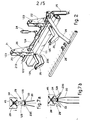
- Fig.2 shows the structure of the upper part of the device 10 in greater detail.
- a pair of arms 22 can be seen on a shaft 124 driven by an actuator 24.
- Lever arms 23, pivoted at 123 on the arms 22, are driven by actuators 26.
- the articulated arm 21 By means of the articulated arm 21 it is possible, as can be seen in Fig.l, to actuate engagement of the roving packages 16 and the transfer of the same onto guides 35.
- the latter consist substantially of channel sections, made of steel plate for instance, with an inlet 135 and outlet 235.
- means 42 are included to clamp the roving packages 16 axially and to impart a rotation thereto at the beginning of the cycle so as to facilitate the unwinding of the new roving 34 without the latter becoming broken.
- Such means 42 serve to enable a given quantity of roving to be unwound during lowering of the arm 28 bearing the end of the roving in the grippers 29, and also to enable the lever arm 23 to be displaced at the same time.
- the means 42 include an actuator 27 with a rack 37.
- rack acts on a toothed wheel 38, which bears a cross-shaped headstock 39 able to engage the end 36 of the support rod 17.
- the actuator 27 bears a support element 41 on which the toothed wheel 38 is pivoted.
- an actuator 40 consisting of a pneumatic cylinder solidly fixed to the other end of the lever arm 23.
- Fig.5 shows a detail of the delivery of the new roving 34 by the arm 28 with the gripper 29 to the aspiration intake 30. It is possible to see the roving currently being processed 33 engaged in the intake 30 and in a drafting unit 44 consisting of a'pair of rolls.
- Such roving 33 passes through a thread-guide 60 and between a stationary blade 132 and movable blade 232 of the scissors 32.
- the movable blade 232 is operated through a transmission 143 by an actuation bar 43, which actuates all the scissors serving the various spinning units.
- the arm 28 is shown in the position where it delivers the new roving 34 to the aspiration intake 30.
- the arm 28 moves towards the intake 30 in the direction of the arrow of Fig.7a.
- the end of the intake 30 causes the opening of the grippers 129, which are kept open by a spring 45 having two stable positions.
- the new roving 34 is caught by the intake 30, and the aspiration action at the surface of the grill 230 produces a first mutual penetration of the fibres of the new and current rovings 33-34.
- a preferred cycle of the exchange of roving packages according to Fig.8.
- the machine operative first of all sets in motion a package pre-arrangement cycle, which takes place when the roving packages 16 are in a suitable position above their respective spinning units, that is to say, a position which enables the packages to be engaged by the articulated arm 21.
- the actuator 26 moves the secondary arm 23 to its raised position 23A of Fig.l for engagement of the roving package 16.
- the secondary arm 23 takes the package 16 from the conveyor 15 by means of terminal engagement hooks 223 cooperating with the pivot ends 36 of the support rod 17.
- the articulated arm 21 is then lowered by the actuator 24 until it has brought the package 16 to position 16A.
- the machine operative positions the new rovings 34 coming from the packages 16 at position 16A between the grippers 29 of the arm 28 in its position 28A; she then actuates closure of the headstocks 39 by means of the actuator 40 by using the push button.
- the grippers 29 are now kept closed by the action of the springs 45 having two stable positions.
- the real cycle for exchanging the roving packages 16, as shown in Fig.8, then begins. First of all the spindles are halted (step 46) and then the aspiration is started (step 49) through the duct 31.
- the aspiration action at the intake 30 aspirates and engages on the grill 230 the roving 33 currently being processed.
- the scissors are actuated (step 50 of Fig.8) and the current roving 33 is sheared.
- the current roving 33 is now engaged only by the drafting unit 44 and aspiration intake 30.
- step 51 the rotation of the drafting roll 20 is inverted (step 51) so as to enable the segment of sheared roving not engaged by the aspiration intake 30 to be re-wound on the rod of the current roving package 33, and also so as to assist the discharge of such rod 17 with its remaining roving.
- the headstocks 39 are now rotated (step 53), and the arm 28 is lowered (step 54) and takes with it the roving 34 of the new package engaged in the gripper 29.
- step 52 The return movement of the secondary arm 23 (step 52) almost at the same time as the previous step brings the new roving package 16 from position 16A to position 16B. Towards the end of this travel the new package 16 presses against the support rod 17, which is thus discharged through the outlets 235 ' of the guides 35. The rod 17 falls onto the conveyor 19 (step 55 of Fig.8) and is removed.
- the rod 17 can be discharged by a mechanical thruster 61, such as a lever or the like, rather than by the new roving package 16.
- the headstocks 39 are opened immediately after the beginning of discharge of the support rod 17 so as to enable the new package 16 to fall into the appropriate guides 35 (step 56).
- Splicing takes place on the grill 230 of the aspiration intake by means of a first intermingling of the fibres when the new 34 and old 33 rovings are brought into contact with each other, as shown in Figs.7a and 7b, for instance.
- step 47 The working of the machine is then re-started (step 47) and the ring carriage 12 is therefore lowered (step 58).
- the splice is perfected by passing through the drafting unit 44 and then receiving false twists from the false twist device 14; thereafter it obtains the real twists by passing through the drafting unit.
- the bobbin 33 is connected up and the splice descends into the underwinding, which will be eliminated, as is known.
- the splice can be made while normal working proceeds, and in this way the splice will remain on the bobbin of yarn.
- the splice which can be made according to the invention is very slender and homogeneous and does not entail problems in the subsequent processes. It can therefore also remain on the bobbin.
- the fuses (step 48) thereafter are halted again and doffing is carried out by any required method.
- Fig.9 shows a variant of the invention in which a rigid arm 121 is comprised instead of the articulated arm 21 of Fig.l.
- This rigid arm 121 takes the roving package 16 from the forked support 18 by being lifted until it engages the ends of the support rod of the roving package 16 and raises such ends from the terminal hooks of the forked support 18.
- the forked support 18 comprises an articulated joint 218 and, as soon as it is freed of the roving package 16, rotates slightly owing to the effect of a counterweight 118 or analogous return means, such as a return spring or the like. In this way the ends of the forked support 18 can no longer engage the package 16.
- the roving 34 is positioned on the gripper 29. Since the engagement position of the package 16A is higher than that in the embodiment of Fig.l, a raised gangway or other analogous means may be provided for the machine operative so as to enable her to position the roving 34 in the gripper 29 by hand in an easy manner.
- the new roving package is put within the support guides 35 by mere clockwise rotation of the rigid arm 121.
- the rod 17 or exhausted roving package is discharged by means of a lever 61 actuated by a pneumatic cylinder.
- the working cycle is analogous to that described earlier.
Landscapes
- Engineering & Computer Science (AREA)
- Mechanical Engineering (AREA)
- Textile Engineering (AREA)
- Spinning Or Twisting Of Yarns (AREA)
Priority Applications (1)
| Application Number | Priority Date | Filing Date | Title |
|---|---|---|---|
| AT86200318T ATE43865T1 (de) | 1985-03-27 | 1986-03-03 | Verfahren und vorrichtung zum wechseln von faserbandwickeln mit automatischer faserbandanknuepfung an spinnmaschinen fuer kardierte wolle. |
Applications Claiming Priority (2)
| Application Number | Priority Date | Filing Date | Title |
|---|---|---|---|
| IT8335185 | 1985-03-27 | ||
| IT8335185 | 1985-03-27 |
Publications (3)
| Publication Number | Publication Date |
|---|---|
| EP0196127A2 true EP0196127A2 (fr) | 1986-10-01 |
| EP0196127A3 EP0196127A3 (en) | 1986-12-10 |
| EP0196127B1 EP0196127B1 (fr) | 1989-06-07 |
Family
ID=11320571
Family Applications (1)
| Application Number | Title | Priority Date | Filing Date |
|---|---|---|---|
| EP86200318A Expired EP0196127B1 (fr) | 1985-03-27 | 1986-03-03 | Procédé et dispositif pour changer des bobines de mèche avec raccordement automatique de mèche à des machines à filer de la laine cardée |
Country Status (5)
| Country | Link |
|---|---|
| US (1) | US4651515A (fr) |
| EP (1) | EP0196127B1 (fr) |
| JP (1) | JPH0657893B2 (fr) |
| AT (1) | ATE43865T1 (fr) |
| DE (1) | DE3663825D1 (fr) |
Cited By (6)
| Publication number | Priority date | Publication date | Assignee | Title |
|---|---|---|---|---|
| EP0274676A1 (fr) * | 1987-01-15 | 1988-07-20 | S. BIGAGLI & C. SpA | Dispositif pour rattacher des mèches de fibres textiles |
| EP0303577A1 (fr) * | 1987-08-10 | 1989-02-15 | OFFICINE GAUDINO di P. GAUDINO & C. S.a.s. | Dispositif automatique pour échanger des bobines de mèche d'un métier à filer des fibres textiles |
| EP0361306A1 (fr) * | 1988-09-21 | 1990-04-04 | Kabushiki Kaisha Toyoda Jidoshokki Seisakusho | Rattache automatique d'une mèche dans une machine textile |
| EP0448518A3 (en) * | 1990-03-22 | 1991-12-04 | Howa Machinery Limited | Method and apparatus for synchronously piecing roving for a continuous feeding thereof to a ring spinning frame |
| US5343689A (en) * | 1990-03-22 | 1994-09-06 | Howa Machinery, Ltd. | Method and apparatus for synchronously piecing roving for a continuous feeding thereof to a ring spinning frame |
| ITUB20155494A1 (it) * | 2015-11-11 | 2017-05-11 | Gbs Srl 59100 Prato / It | Dispositivo automatico per la alimentazione dei subbi di stoppino in una filanda |
Families Citing this family (2)
| Publication number | Priority date | Publication date | Assignee | Title |
|---|---|---|---|---|
| DE3817405A1 (de) * | 1988-05-21 | 1989-11-30 | Fritz Stahlecker | Verfahren und vorrichtung zum spulenwechseln |
| CN110106588B (zh) * | 2019-04-25 | 2024-05-07 | 江阴高瓴智能科技有限公司 | 一种便于更换纱锭的环锭细纱机 |
Family Cites Families (9)
| Publication number | Priority date | Publication date | Assignee | Title |
|---|---|---|---|---|
| US869044A (en) * | 1905-03-29 | 1907-10-22 | William H Arnold-Forster | Apparatus for doffing spools from the spindles of fly-frames. |
| BE620116A (fr) * | 1962-07-12 | |||
| GB1137879A (en) * | 1965-06-16 | 1968-12-27 | Bielska Fabryka Masz Wlokienni | Ring spinning frames |
| BE698218A (fr) * | 1967-05-09 | 1967-10-16 | ||
| DE2521851A1 (de) * | 1975-05-16 | 1976-11-25 | Schlafhorst & Co W | Verfahren und vorrichtung zum wechseln der faserbandbehaelter einer spinnmaschine |
| ES8203999A1 (es) * | 1981-03-10 | 1982-05-01 | Pons Ubach Antonia | Aparato automatico para la alimentacion de mecha en maquinascontinuas de hilar |
| GB2102032B (en) * | 1981-05-18 | 1984-12-19 | Pacini Cesare | False twist drafting device for continuous working of slubbings of textile materials |
| IT1210503B (it) * | 1982-10-12 | 1989-09-14 | Savio Spa | Filatoi di tipo open-end.dispositivo perfezionato di riattacco filo e levata rocche per |
| US4473997A (en) * | 1983-04-29 | 1984-10-02 | Howa Kogyo Kabushiki Kaisha | Method and apparatus for switching roving bobbins in a spinning frame |
-
1986
- 1986-03-03 DE DE8686200318T patent/DE3663825D1/de not_active Expired
- 1986-03-03 EP EP86200318A patent/EP0196127B1/fr not_active Expired
- 1986-03-03 AT AT86200318T patent/ATE43865T1/de not_active IP Right Cessation
- 1986-03-25 JP JP61066992A patent/JPH0657893B2/ja not_active Expired - Fee Related
- 1986-03-27 US US06/844,588 patent/US4651515A/en not_active Expired - Lifetime
Cited By (6)
| Publication number | Priority date | Publication date | Assignee | Title |
|---|---|---|---|---|
| EP0274676A1 (fr) * | 1987-01-15 | 1988-07-20 | S. BIGAGLI & C. SpA | Dispositif pour rattacher des mèches de fibres textiles |
| EP0303577A1 (fr) * | 1987-08-10 | 1989-02-15 | OFFICINE GAUDINO di P. GAUDINO & C. S.a.s. | Dispositif automatique pour échanger des bobines de mèche d'un métier à filer des fibres textiles |
| EP0361306A1 (fr) * | 1988-09-21 | 1990-04-04 | Kabushiki Kaisha Toyoda Jidoshokki Seisakusho | Rattache automatique d'une mèche dans une machine textile |
| EP0448518A3 (en) * | 1990-03-22 | 1991-12-04 | Howa Machinery Limited | Method and apparatus for synchronously piecing roving for a continuous feeding thereof to a ring spinning frame |
| US5343689A (en) * | 1990-03-22 | 1994-09-06 | Howa Machinery, Ltd. | Method and apparatus for synchronously piecing roving for a continuous feeding thereof to a ring spinning frame |
| ITUB20155494A1 (it) * | 2015-11-11 | 2017-05-11 | Gbs Srl 59100 Prato / It | Dispositivo automatico per la alimentazione dei subbi di stoppino in una filanda |
Also Published As
| Publication number | Publication date |
|---|---|
| EP0196127B1 (fr) | 1989-06-07 |
| DE3663825D1 (en) | 1989-07-13 |
| US4651515A (en) | 1987-03-24 |
| JPH0657893B2 (ja) | 1994-08-03 |
| JPS61266621A (ja) | 1986-11-26 |
| EP0196127A3 (en) | 1986-12-10 |
| ATE43865T1 (de) | 1989-06-15 |
Similar Documents
| Publication | Publication Date | Title |
|---|---|---|
| EP0348678B1 (fr) | Procédé pour saisir et introduire une mèche dans un métier à filer à bout libre et dispositif pour la mise en oeuvre de ce procédé | |
| US4899531A (en) | Method and apparatus for automatic exchange of roving bobbins of a ring spinning machine | |
| CN104816981B (zh) | 筒管安装装置以及纱线卷取机 | |
| US4638955A (en) | Yarn handling apparatus for winding machine | |
| CZ146091A3 (en) | Process and apparatus for automatic feeding a fiber strand to a textile machine | |
| US4653263A (en) | Process for piecing yarn on an open end spinning machine | |
| CN111441112B (zh) | 一种纺纱装置及其自动落纱和上纱方法 | |
| DE3801965A1 (de) | Verfahren und einrichtung zum raschen wiederherstellen des spinnbetriebs | |
| EP0196127B1 (fr) | Procédé et dispositif pour changer des bobines de mèche avec raccordement automatique de mèche à des machines à filer de la laine cardée | |
| US4178748A (en) | Open-end spinning machine apparatus with a traveling device for bobbin exchange and method of using same | |
| DE4443818B4 (de) | Kreuzspulen herstellende Textilmaschine | |
| US5473879A (en) | Open-end spinning machine for producing cross-wound bobbins | |
| US4389840A (en) | Method of automatically doffing the full bobbin packages from, and donning the empty bobbin tubes onto, the spindles of a preparatory spinning machine | |
| US4987645A (en) | Automatic piecing of overlapped leading and trailing ends of slivers in a textile machine | |
| JPH0351331A (ja) | 精紡機における糸取扱い方法並びに装置 | |
| US6662542B2 (en) | Open-end spinning device and process for temporary receiving a yarn | |
| EP0303577B1 (fr) | Dispositif automatique pour échanger des bobines de mèche d'un métier à filer des fibres textiles | |
| US3398522A (en) | Textile machine | |
| JPH03505240A (ja) | 紡績機の作動方法及びその方法を実施するためのサービスロボット | |
| EP0320802A1 (fr) | Procédé et dispositif pour la fabrication d'une bobine croisée | |
| SK277982B6 (en) | Method of trapping, treatment and leading of sliver end into the spinning unit of open-end spinning machine and device for realization of this method | |
| EP0419968B1 (fr) | Manipulation de bobines de mèche et de mèche dans un métier à filer | |
| CN213203307U (zh) | 一种基于agv车的须条接头装置 | |
| EP1769110B1 (fr) | Appareil et procede d'insertion et de preacheminement de ruban dans une unite de filage | |
| JPH01192837A (ja) | 篠換機における篠切断装置 |
Legal Events
| Date | Code | Title | Description |
|---|---|---|---|
| PUAI | Public reference made under article 153(3) epc to a published international application that has entered the european phase |
Free format text: ORIGINAL CODE: 0009012 |
|
| AK | Designated contracting states |
Kind code of ref document: A2 Designated state(s): AT BE CH DE FR GB LI NL |
|
| PUAL | Search report despatched |
Free format text: ORIGINAL CODE: 0009013 |
|
| AK | Designated contracting states |
Kind code of ref document: A3 Designated state(s): AT BE CH DE FR GB LI NL |
|
| 17P | Request for examination filed |
Effective date: 19870506 |
|
| 17Q | First examination report despatched |
Effective date: 19880526 |
|
| GRAA | (expected) grant |
Free format text: ORIGINAL CODE: 0009210 |
|
| AK | Designated contracting states |
Kind code of ref document: B1 Designated state(s): AT BE CH DE FR GB LI NL |
|
| PG25 | Lapsed in a contracting state [announced via postgrant information from national office to epo] |
Ref country code: NL Effective date: 19890607 Ref country code: LI Effective date: 19890607 Ref country code: CH Effective date: 19890607 Ref country code: AT Effective date: 19890607 |
|
| REF | Corresponds to: |
Ref document number: 43865 Country of ref document: AT Date of ref document: 19890615 Kind code of ref document: T |
|
| REF | Corresponds to: |
Ref document number: 3663825 Country of ref document: DE Date of ref document: 19890713 |
|
| ET | Fr: translation filed | ||
| REG | Reference to a national code |
Ref country code: CH Ref legal event code: PL |
|
| NLV1 | Nl: lapsed or annulled due to failure to fulfill the requirements of art. 29p and 29m of the patents act | ||
| PLBE | No opposition filed within time limit |
Free format text: ORIGINAL CODE: 0009261 |
|
| STAA | Information on the status of an ep patent application or granted ep patent |
Free format text: STATUS: NO OPPOSITION FILED WITHIN TIME LIMIT |
|
| 26N | No opposition filed | ||
| REG | Reference to a national code |
Ref country code: FR Ref legal event code: CL |
|
| REG | Reference to a national code |
Ref country code: GB Ref legal event code: IF02 |
|
| PGFP | Annual fee paid to national office [announced via postgrant information from national office to epo] |
Ref country code: GB Payment date: 20030305 Year of fee payment: 18 |
|
| PGFP | Annual fee paid to national office [announced via postgrant information from national office to epo] |
Ref country code: FR Payment date: 20030310 Year of fee payment: 18 |
|
| PGFP | Annual fee paid to national office [announced via postgrant information from national office to epo] |
Ref country code: DE Payment date: 20030313 Year of fee payment: 18 |
|
| PGFP | Annual fee paid to national office [announced via postgrant information from national office to epo] |
Ref country code: BE Payment date: 20030522 Year of fee payment: 18 |
|
| PG25 | Lapsed in a contracting state [announced via postgrant information from national office to epo] |
Ref country code: GB Free format text: LAPSE BECAUSE OF NON-PAYMENT OF DUE FEES Effective date: 20040303 |
|
| PG25 | Lapsed in a contracting state [announced via postgrant information from national office to epo] |
Ref country code: BE Free format text: LAPSE BECAUSE OF NON-PAYMENT OF DUE FEES Effective date: 20040331 |
|
| BERE | Be: lapsed |
Owner name: S. *BIGAGLI & C. S.P.A. Effective date: 20040331 |
|
| PG25 | Lapsed in a contracting state [announced via postgrant information from national office to epo] |
Ref country code: DE Free format text: LAPSE BECAUSE OF NON-PAYMENT OF DUE FEES Effective date: 20041001 |
|
| GBPC | Gb: european patent ceased through non-payment of renewal fee | ||
| PG25 | Lapsed in a contracting state [announced via postgrant information from national office to epo] |
Ref country code: FR Free format text: LAPSE BECAUSE OF NON-PAYMENT OF DUE FEES Effective date: 20041130 |
|
| REG | Reference to a national code |
Ref country code: FR Ref legal event code: ST |