EP0419968B1 - Manipulation de bobines de mèche et de mèche dans un métier à filer - Google Patents
Manipulation de bobines de mèche et de mèche dans un métier à filer Download PDFInfo
- Publication number
- EP0419968B1 EP0419968B1 EP19900117733 EP90117733A EP0419968B1 EP 0419968 B1 EP0419968 B1 EP 0419968B1 EP 19900117733 EP19900117733 EP 19900117733 EP 90117733 A EP90117733 A EP 90117733A EP 0419968 B1 EP0419968 B1 EP 0419968B1
- Authority
- EP
- European Patent Office
- Prior art keywords
- strand
- machine
- creel
- package
- spinning
- Prior art date
- Legal status (The legal status is an assumption and is not a legal conclusion. Google has not performed a legal analysis and makes no representation as to the accuracy of the status listed.)
- Expired - Lifetime
Links
Images


Classifications
-
- D—TEXTILES; PAPER
- D01—NATURAL OR MAN-MADE THREADS OR FIBRES; SPINNING
- D01H—SPINNING OR TWISTING
- D01H15/00—Piecing arrangements ; Automatic end-finding, e.g. by suction and reverse package rotation; Devices for temporarily storing yarn during piecing
-
- D—TEXTILES; PAPER
- D01—NATURAL OR MAN-MADE THREADS OR FIBRES; SPINNING
- D01H—SPINNING OR TWISTING
- D01H9/00—Arrangements for replacing or removing bobbins, cores, receptacles, or completed packages at paying-out or take-up stations ; Combination of spinning-winding machine
- D01H9/005—Arrangements for replacing or removing bobbins, cores, receptacles, or completed packages at paying-out or take-up stations ; Combination of spinning-winding machine for removing empty packages or cans and replacing by completed (full) packages or cans at paying-out stations; also combined with piecing of the roving
Definitions
- the invention relates to an apparatus and a process for manipulating feed packages or feed strands in a spinning machine, and to a spinning machine with such apparatus.
- the invention is intended in particular for use in connection with apparatus according to our European patent application No. 90106217.4 of 31 March 1990 ("Transporting packages of spinnable strand in and to the creel of a textile machine"), and the corresponding PCT application No. PCT/EP90/00517.
- the invention can also be applied in combination with other equipment.
- the invention therefore foresees a travelling device for manipulating (handling) of strand packages or of strands at a spinning machine.
- the spinning machine can be a ring spinning machine or another type of spinning machine having a spinning position fed by strand packages.
- the device in accordance with the invention is characterised in that it is provided both with means for introducing a new strand package into the creel and also with means to make a strand end ready for introduction into a spinning position.
- the spinning position can comprise a drafting arrangement so that the introduction of the strand into the spinning position necessitates threading of the strand into the drafting arrangement.
- the device can preferably travel on at least one rail in the creel or above the creel so that in performing its function the means for making ready of the strand end extends downwardly or laterally from the device into the creel.
- the device is preferably provided with two different means, one of the said means being adapted for introducing of a package into the creel and the other being adapted for making ready of a strand end.
- the means for making ready of a strand end can be arranged to introduce the strand into a joining device so that this device operates at a suitable point of time to join the new strand with a strand already running to the spinning position, for example in accordance with our European patent application No. 296 546.
- This means could, however, also be designed to thread the strand into a continually running drafting arrangement (for example in accordance with DOS 36 26 268 or EP 310 906).
- this means can be provided with a strand piecing device (for example in accordance with EP 213 962 or DOS 38 02 414) so that the device itself forms a suitable join between the new strand and the strand already running to the spinning position.
- the machine is preferably provided with a sensor system in order to determine the appropriate point of time for the join to be made, and with an indicating means to indicate that this point of time has been reached.
- the sensor system can be formed in accordance with our German patent application No. 39 00 507 or in accordance with DDR-PS 252592.
- the travelling device can be provided with its own sensor means to recognise the indication provided by the machine.
- communication means could be provided to enable transfer to the travelling device of a signal regarding the necessity for a strand joining operation at an identifiable spinning position.
- the strand may be threaded into a drafting unit of the spinning position in preparation for a subsequent yarn piecing operation performed by a separate robot.
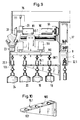
- Figure 15 shows in longitudinal elevation a ring spinning machine 220 supported by feet 222 on the floor 224 of the spinning room.
- the machine comprises a frame work made up of transverse supports ("Samsons") 226 carrying longitudinal elements which extend along the whole length of the machine.
- the machine is symmetrical about a central longitudinal plane CP that is, the machine is "double-sided" with two rows of spinning positions facing outwardly in opposite directions from this central plane.
- Each spinning position comprises a drafting section 228 and spindle unit 230 with thread guiding elements 232 between the drafting section and the spindle unit.
- Each spinning position can be of generally conventional construction, and is therefore illustrated only in general outline in Figure 15 without any detail.
- Suitable drive arrangements are provided for both the drafting section 228 and the spindle unit 230.
- the machine also comprises a pneumatic system including a suction channel 234 extending longitudinally thereof and having branch tubes (not shown) communicating with respective spinning positions to collect waste material therefrom.
- a pneumatic system including a suction channel 234 extending longitudinally thereof and having branch tubes (not shown) communicating with respective spinning positions to collect waste material therefrom.
- branch tubes not shown
- One such end head is indicated in outline at 235 in Figure 15.
- a modern machine will normally be provided with an automatically operating doffer for removing completed yarn packages from the spindle units 230 and replacing them with fresh tubes ready for winding of new yarn packages.
- a doffing mechanism is indicated at 237 in a "packed away" condition. The doffing mechanism remains in this condition during normal spinning operation, but must be extended outwards and upwards for a doffing operation. Since the latter is not affected by this invention, the extended condition of the doffer is not shown.
- a modern ring spinning machine includes a large number of spinning positions, for example 1000 to 1200 such positions equally divided between the two rows on opposite sides of plane CP.
- Service personnel or a service tender for tending the individual spinning positions can stand (be supported) on floor 224 and can move freely along the machine with good access to the individual spinning positions.
- a spinning position servicing tender is shown in general outline at 239. Details of such tenders can be seen from European patent application No. 90106217, but this invention is not restricted to use in combination with service tenders of that kind.
- each support 240 normally carries two suspension devices 242 on which roving tubes 244 are suspended to hang freely from the respective suspension device 242.
- each tube 244 When it is first mounted in the creel 236, each tube 244 carries a package 246 of roving to be spun in a respective spinning position associated with that particular transverse support 240.
- Roving withdrawn from this package is passed over suitable guides, for example longitudinal guide rods 248 mounted on the support posts 238, so as to run from the respective packages over the associated guides into the individual drafting sections 228.
- suitable guides for example longitudinal guide rods 248 mounted on the support posts 238, so as to run from the respective packages over the associated guides into the individual drafting sections 228.
- the run of roving has been omitted from Figure 15 in order to maintain clarity of the overall illustration and because this arrangement is well-known to the man skilled in the spinning art.
- roving packages that is packages of slightly twisted strand prepared on a roving frame.
- the invention is clearly not limited to machines based on a roving feed. Ring twisting machines for example, take yarn packages as infeed.
- the creel In order to maintain the service area immediately adjacent the spinning positions clear, the creel is normally disposed so that the suspended packages are held above head height for service personnel or above any region which has to be crossed by a service tender.
- the conventional supports 240 can be converted into transverse paths along which roving packages and/or package tubes can be moved to and from a delivery system transporting the packages and/or tubes to and from the ring spinning machine.
- Each transverse path 240 can be extended as indicated in dotted lines at 258 to provide space for a reserve position such that a newly delivered full package 254 can be moved from the outermost conveying path 256 into a reserve position of an individual transverse path while the working positions (illustrated in full lines) are still occupied by at least partially wound packages delivering strand to the respective spinning positions.
- Figure 1 shows an overhead transport rail 5 which leads from a roving frame 6 via a points system 7 into a respective overhead rail 11 encircling a ring spinning machine 10.
- the overhead rail 11 extends along both longitudinal sides of the machine 10.
- the machine comprises a drive head 13 and second end housing 12 with spinning positions (not illustrated in Figure 1) in two rows along respective longitudinal sides of the machine 10.
- the machine further comprises a creel provided above the spinning positions and including creel paths 16 in the form of rails which are arranged (when viewed in plan) at right angles to the central longitudinal plane 17 of the machine.
- the rails 17 are preferably horizontal but can also have a small angle to the horizontal in the vertical plane.
- Each rail leads through the operating or working positions of the packages for the associated spinning position. There are two such positions, namely the first operating position 18 and the second operating position 19. Each rail also leads through a reserve position 20. It would of course be possible to provide one points device for each machine side. In this case, two different overhead transport rails could be provided for the respective longitudinal sides of the ring spinning machine 10.
- a carrier train or trolley 23 brings full packages 24 from the overhead transport system 5 onto the overhead rail 11 associated with the machine.
- the train or trolley 23 can be driven on the system 5 and/or on the rail 11 by means of a drive motor, a friction roller drive or by means of a chain drive (for example in accordance with DOS 37 28 843).
- Each package 24 has its own associated support element 25 with which the package 24 remains in association throughout the operation to be described in this specification.
- Each support 25 has a pair of limbs 85 ( Figure 3) defining an opening to receive a rail 16 and each having a free end. The free ends of limbs 85 together form a releasable connection with an inverted U-shaped intermediate portion 26 fixedly connected with the trolley 23.
- the creel rails 16 are not joined continuously by stationary points devices with the encircling rail 11. Instead, a travelling transfer device 29 is provided which is adapted to move packages along a creel rail 16 and "simultaneously" (as part of the same transfer operation) to transfer a new full package 24 onto the same creel rail.
- the transfer device 29 can travel in the region above the creel rails 16 on its own guide rails 30, being supported by means of rollers 31.
- the transfer device 29 may or may not be self driven, but it will include at least means for performing a transfer function for transferring packages into and through the creel in a direction towards the central longitudinal plane 17.
- the transfer device When a package at position 18 becomes empty through supply of its strand to an associated spinning position, the transfer device not only transfers a new full package 24 from the trolley 23 onto the appropriate rail 16 but also transfers almost simultaneously the packages already present on that rail at positions 20, 19, 18 in a direction towards the plane 17. This transfer operation is carried out in such manner that the empty package at position 18 is transferred from the rail 16 onto one of the support pins 33 of the stationary intermediate storage belt 32.
- the direction of movement of the packages on the rail 16 is illustrated in Figure 1 by means of arrows.
- At least one creel path or rail 36 which is disposed parallel to the rails 16 of the creel, serves to return the empty packages from the receiving belt 32 back to the carrier train 23.
- the transfer device 29 is dragged along by the trolley 23 by means of a drag lever 38 which engages on the intermediate portion 26. Trolley 23 and transfer device 29 are moved in the direction of the arrow A.
- An initiator device 39 in the form of a pivotable lever moves with only a low degree of play along the outer ends of the rail 16.
- Operation of the initiator 39 sets a motor 43 in operation causing rotation of an eccentric disc 44 and motion of a rod 45.
- the connector rod 45 causes pivotable movement of a body 49 around a threaded spindle 50. This pivotable movement of body 49 continues until the body comes into engagement with the flange 51 and possibly the upright 52 of the rail 16. It is advantageous to arrange for variable speed of rotation of the drive to the trolley 23 so that after the initiator 39 has been operated the drive can be switched into a crawl gear. This reduces or prevents a disturbing swinging of the packages on the trolley 23.
- a transfer motor 55 is activated and rotates the threaded spindle 50 by way of a chain 56.
- the body 49 is thereby moved in a direction towards the central longitudinal plane 17 of the machine.
- Body 49 is provided with a pusher rod 57 which in the illustrated case is fitted with three grippers 58. These grippers 58 come into engagement with the supports 25 and move the packages carried by the rail along that rail.
- the package previously at position 18 passes from the rail 16 onto a support pin 33 on the central belt, and the reserve position 20 becomes empty.
- the package previously at working position 19 is moved inwards into working position 18 and the package previously at the reserve position 20 is moved into working position 19.
- the carrier train 23 is still engaging (via the intermediate part 26) with the spring biased drag lever 38 and is pushing the latter into the position illustrated in dotted lines.
- Motion of the drag lever 38 into the dotted line position moves the front support 25 on the trolley past a transfer head 61 on a dog-leg lever 62 pivotally mounted on the transfer device 29.
- transfer head 61 is itself held by means of a spring bias (not shown) on the lever 62.
- drag lever 38 reaches the dotted line position, the front support 25 is taken up by a curved intermediate rail section 63 which is fixedly mounted on the transfer device 29 and is aligned at this time with the relevant rail 16.
- a further, pivotally mounted transfer motor 64 is activated and swings the dog-lever 62 by means of a threaded spindle 65.
- the swinging movement of lever 62 causes movement of the front support 25 together with a package 24 carried thereby along the intermediate rail section 63 and onto the rail 16 aligned therewith. Movement of the support 25 continues until it occupies the reserve position 20.
- the body 49 is still resting in engagement with the rail 16.
- the body 49 is pivoted slightly upwards and is moved in a direction away from the longitudinal central plane 17 of the machine. This slight upward pivotal movement enables return movement of the grippers 58. During this return movement, the body 14 remains in engagement with the flange 51 of the rail 16. This is enabled by providing the flange 51 and the engaging portion of the body 49 with the same radius 68.
- Pusher rod 57 could also be formed with a telescoping spring-bias structure if a predetermined sequence of operating times is required for the grippers 58.
- Drag lever 38 which is provided with a roller 69 running on a curved guide 70 having a curved end section, is still pressed by a spring force from the trolley 23 in the direction of the arrow A.
- roller 69 moves onto the curved section of guide 70 the drag lever pivots in a direction towards the central longitudinal plane 17 (away from the trolley 23) and enables further travel of the intermediate part 26 (that is, of the carrier train 23).
- the spring force then moves the drag lever 38 back into the position illustrated in full lines and the succeeding intermediate portion 26 carrying a full package 24 comes into engagement with the drag lever 38 due to the movement of the carrier train 23.
- the transfer device 29 slides backwards relative to the trolley 23 through one spacing on the trolley or train 23.
- the transfer device remains stationary relative to the ring spinning machine.
- the way in which the empty packages 18 can be transferred from the intermediate storage band 32 back to the trolley 23 is also shown in our European patent application No. 90106900.
- the limb 71 of the drag lever 38 which engages the intermediate portion 26 of the trolley has a length such that the trolley 23 together with the transfer device 29 coupled therewith can travel easily and without tipping around the curves 72 of the rail 11 encircling the machine.
- All movement sequences involved in the transfer operation that is shifting of the package 24 via the intermediate curved rail section 63, lowering and then pivoting upwards of the body 49, displacement of the packages on the rail 16, and the return movement of the grippers 58, are controlled by electrical means and carried out by electromechanical means. These sequences are therefore independent of the movement of the carrier train 23. Accordingly, it is possible to hold the trolley 23 stationary during the package exchange operation. Coordination of the various movement sequences is ensured by a microprocessor 75. Electrical current is provided to the transfer device 29 by means of a sliding contact 77 engaging one or more current buses 76.
- Figure 5 shows a second embodiment of transfer device 29 which in this case is formed as a locomotive for the train.
- the device is self-drivable by means of a motor 81 coupled with at least one roller 31.
- Electrical current is provided to all motors arranged on the locomotive 29 from an accumulator 82 which can be periodically recharged by means of a charging station 83 arranged at one of the curved ends 72 of the encircling rail 11.
- the curved intermediate rail section 63 of Figure 2 is replaced by a straight intermediate rail section 84.
- This straight intermediate section 84 can be made superfluous provided that either the rail 16 of the creel can be extended or that the encircling rail 11 for the support train 23 can be arranged very close to the ends of the creel rails 16. In either case, the creel rails 16 extend into the immediate neighbourhood of the carrier train 23.
- the supports 25 have (as regards the section made up by the limbs 85) an orientation rotated through 90 degrees relative to the first embodiment (compare Figure 3 with Figure 8).
- the longitudinal axis of the support 25 undergoes a change of direction in the course of a transfer movement from the carrier train 23 onto a rail 16. This change of direction of the support 25 is unnecessary in the case of an embodiment in accordance with Figure 5. This simplifies the return of the empty packages from the receiving path 32 via the rail 37 onto the carrier train 33.
- the pusher rod 57 is now provided with four grippers 58 and the movement sequence is simplified.
- the packages on the rail 16 are displaced in the direction of the central longitudinal plane 17 of the machine, and also the package 24 aligned with this particular rail 16 is shifted from the carrier train 23 onto the rail 16.
- the inner package initially at position 18 passes from the rail 16 onto a receiving pin 33 on the central receiving path.
- the sequence is reversed in the case of return of empty packages. In the latter case, a linear movement occurs from the receiving pin 33 of the central conveying path via the rail 37 onto the carrier train 23.
- the locomotive transfer device 29 can also be used for the return of packages onto the carrier train 23. It is therefore unnecessary to provide an additional package returning means for this purpose.
- the initiating device 95 in this case is in the form of a sensor having a sensing field corresponding to the length of a package supporting tube and it responds to the presence of the strand 99 in this sensing field.
- a sensor 100 can be provided to respond to the presence of the strand 96.
- sensors 101 ( Figure 7) are provided, preferably as a pair, to detect the dimensions of the strand body remaining in the innermost package (at position 18).
- An effective operating procedure is as follows.
- the locomotive 29 alone (without the carrier train 23) travels along its guide rails and detects by means of the sensors 95, 100 or 101 those creel rails 16 requiring a package change.
- the data derived by means of this sensing operation is stored in the microprocessor 75 and passed to a central control (not shown).
- the central control can then direct a carrier train 23 from the roving frame 6 via the transport rail 5 onto the appropriate rail 11 encircling the relevant ring spinning machine.
- the locomotive or transfer device 29 is coupled to the front end of the carrier train 23 at the first creel rail 16 (as viewed from the points device 7) at which a package change operation is required.
- This coupling can be formed by means of a non-illustrated entrainment lever or means of a gear wheel 98.
- Packages 24 of the carrier train 23 can then be transferred sequentially onto those creel rails 16 which have already been identified as in need of a package change operation and have been stored in the microprocessor 75.
- the transfer device can transmit a signal to the control center indicating that the train 23 no longer carries any full packages 24.
- the return of packages to the train can then be initiated, again from the control center.
- the locomotive transfer device 29 is guided to the return creel rail 37 and the intermediate storage belt 32 is set in motion.
- the carrier train 23 with, for example, approximately sixty packages 24, can be guided via the points device 7 onto the encircling rail 11 and can be positioned in alignment with the first sixty creel rails 16 (viewed from the points device 7).
- the transfer device 29 with the stored data regarding creel rails 16 upon which a package exchange operation is required can now extract those packages 24 from the carrier train 23 lying opposite rails 16 upon which a package exchange operation is necessary.
- the transfer device 29 acting as a locomotive can move the carrier train along the machine to the next following section of sixty creel rails.
- the carrier train 23 no longer carries a continuous row of packages 24.
- this is unlikely to prove a major disadvantage because the sensor 91 of the locomotive 29 can automatically locate the packages 24 on the carrier train 23 in passing the train.
- the locomotive 29 therefore services within this second section all of those rails 16 which are currently aligned with a full package 24 on the train 23.
- the locomotive 29 can displace the train 23 by means of the gear wheel 89 until a full package 24 lies opposite the relevant rail 16.
- the supports for packages are here formed as cylindrical elements 25.1.
- the creel rails 16.1 each consist of two yokes 105 arranged at a small spacing such that the shaft 106 of the supports 25.1 can be moved along between a pair of yokes 105.
- Each yoke 105 is provided with recesses 107, the recesses of a pair of yokes 105 together corresponding to the section of the cylindrical supports 25.1.
- the holders for the package 24 on the carrier train 23, and the holders for the packages 24 on the receiving belt 32.1 are correspondingly formed as forked elements.
- Both runs of the receiving belt 32.1 are arranged to one side of the central longitudinal plane 17 of the machine.
- the locomotive transfer device has a yoke 110 on which grippers 58.1 in the form of Casablanca pins are secured. Alternative possibilities involve for example magnets.
- the yoke 110 and the grippers 58.1 grasp the supports 25.1 centrally.
- the packages already on the rail at positions 20, 19, 18 are gripped simultaneously and are lifted by pneumatic, hydraulic or (preferably) electromechanical lifting and lowering means 111.
- the means 111 are provided in a shifting body 49.1.
- the packages are shifted through one step in the direction of the central longitudinal plane 17 of the machine (position B) and are lowered (position C).
- the lowering movement causes release of the packages by the grippers 58.1.
- the packages are therefore transferred in a series "jumps" along the creel rails 16.1.
- the return of the empty packages can in this case also be carried out by means of the locomotive transfer device.
- the suction system comprises a source of underpressure (not illustrated here) which in a system according to European patent application No. 89123852 is mounted on a chassis of a piecing robot.
- the source of underpressure will be mounted upon the chassis of the transfer device in accordance with the latter application.
- the suction system further comprises a storage tube 134 ( Figure 11) which is connected to the source of underpressure and is fitted with a mouth portion 136.
- Mouth portion 136 of the suction system is preferably formed by a rigid element for example a metallic tube 166.
- This rigid part 166 can be held in a holder 168 so that the movements of the mouth 170 are clearly defined by the corresponding movements of the holder 168.
- the storage tube 134 should be formed as a flexible tube, for example being formed of flexible plastics material.
- the storage tube 134 can therefore be connected both with the source of underpressure and with the movable part 166, and can adapt itself to the movements of the latter part without prejudicing the precision of the definition of those movements by the control program.
- the suction effect exerted from the source of underpressure in the storage tube 134 should be able to hold a predetermined length of fibre strand in a kink-free manner within the suction tube.
- the suction effect must allow the strand to be drawn out of the suction tube in the course of a piecing operation or a strand manipulating operation as will subsequently be described.
- the pivoting system preferably comprises rigid elements connected together by pivot axes.
- the holder 168 is supported by a first arm 172 which is connected by a pivot axis 174 with a second arm 176.
- the pivot axis 174 is preferably arranged horizontally as will be apparent in particular from the plan view in Figure 10 and the side view in Figure 12.
- the pivot arm 172 is rotatable about the axis 174 by means of a motor (not shown) supported by the second arm 176. This motor can be controlled by means of the control program to move the mouth portion 136 ( Figure 11, not shown in Figures 12 and 13).
- the holder 168 must also be able to rotate about a vertical axis.
- This vertical axis 178 ( Figure 12) is located between the second arm 176 and two support plates, namely an upper plate 180 and a lower plate 182 ( Figure 12). These two support plates are connected with a further plate 184 to form a raisable and lowerable carriage 186.
- a further horizontal pivot axis 188 is provided between the second arm 176 and the vertical pivot axis 178.
- This pivot axis 188 is carried by a housing portion 190 ( Figure 11) which is cast in one piece with a sleeve 192 ( Figure 12) encircling the pivot axis 178.
- a motor (not shown) causes rotational movements of the arm 176 around the pivot axis 188 in accordance with a stored control program.
- a further motor (also not shown) moves the housing portion 190 (with the axis 188) around the axis 178, also in accordance with a control program.
- the arm 172 with the holder 168 can be extended from the robot into a spinning position to be serviced or can be retracted back into the travelling robot. This is enabled by appropriate rotational movements of the arm 176 around the axis 188.
- the controlled movements of the lever system 172, 176 around the vertical pivot axis 178 enable the (horizontal) displacements of a predetermined movement sequence.
- the vertical components are generated by pivoting of the arms 172, 176 around the horizontal axis 174, 188.
- the use of the two horizontal pivot axes enables the presentation of the free end (that is of the strand guiding element) to any desired position within a three-dimensional space.
- a simple lever would only enable the presentation of the free end to points on the surface forming the boundary of the same three-dimensional space.
- the pivoting system is carried by a linearly movable carriage to enable performance of certain functions.
- the linear movements of the carriage 186 are caused by rotation of the threaded spindle 196 ( Figure 11), this spindle being carried by a chassis (not shown). Movements of the carriage 186 are guided by means of a vertical guide rod 198 ( Figure 11).
- the movements of the arms 172, 176 are controlled by a programmable control system, namely in the following manner:
- the central control is therefore designed as a sequential control system giving instructions and commands ("orders") to a system with distributed intelligence after the central control itself has received reports that the previously issued orders have been carried out (that is that a predetermined condition has been achieved within the system).
- the carriage 186 is now mounted upon the chassis of a travelling device in accordance with European patent application No. 90106217 (instead of upon the chassis of a piecing robot in accordance with European patent application No. 89123852).
- This mounting may be effected in such manner that the threaded spindle 196 ( Figure 11) and the guide rod 198 are disposed horizontally (instead of vertically, as in European patent application No. 89123852).
- the movements of the carriage 186 in this case do not serve to determine the "working height" of the pivoting system but to determine an operating position in the longitudinal direction of the rails 16 ( Figure 1) of the creel.
- the modified equipment could operate in the following manner:
- the first problem to be treated is that of timing.
- possibilities 4.A. and 4.B. strand manipulation can be carried out immediately adjoining upon the transfer of the new package from the train into the reserve position.
- the problems of appropriate positioning of the manipulating device are therefore solved because appropriate positioning of the combined transfer device and strand handling equipment is required in any event for the transfer operation.
- Possibility 4.D. can be carried out at any time after one of the packages has run out. This requires a thread break in the associated spinning position and possibly an associated loss of production at this spinning position.
- the positioning operation (step 1 of the complete procedure) can be the same for the transfer of a package into the creel and for the strand manipulation operation. This will, however, influence the possible positions of the pivoting system ( Figures 11 to 13) relative to the chassis.
- the mouth portion 166 ( Figure 11) must be provided with an appropriate end portion, for example in accordance with Figure 14.
- the adapted end portion 166A has a widening 167 at its free end which is better suited for sucking in a strand end lying on the surface of the package.
- the form of this end portion can be adapted to the curvature of the package surface (as indicated in dotted lines in Figure 14).
- the strand end could also be grasped by a mechanical gripper.
- the suction system has the advantage that a sensor can be provided to detect the presence of the strand end in the tube 134 so that the robot then "knows” that it has grasped a strand for performance of a manipulation operation.
- the strand end should where possible be positioned or held at a predetermined position on the surface of the package in order to facilitate the end finding operation. It may also be necessary to rotate the package in the course of a manipulating operation in order to reduce the risk of "loosing" of the strand end in the course of the manipulation.
- the robot can be provided with an extendable device for rotating of the new package.
- a device of this kind has not been shown in Figures 11 to 13.
- the strand After the strand has been gripped, it can be manipulated by the pivoting system, as has already been indicated above.
- the new strand end can be brought into the neighbourhood of the strand which is running out (for example the strand 96, Figure 6).
- a splicing operation for example in accordance with DOS 38 02 414 or EP 213 962, can then be carried out.
- the pivoting system could be provided with a severing means for parting the strand which is running out and, for example, with a nozzle similar to the nozzle indicated with the reference numeral 17 in DOS 38 02 414.
- the invention is not limited to the use of a device in accordance with European patent application No. 90106217.
- the described pivoting system, or a similar second pivoting system could also be used to transfer the packages from the train into the creel.
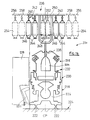
- FIG. 16 One embodiment of a combined package transfer and strand handling robot according to this invention is shown in diagrammatic section in Figure 16.
- This Figure shows one side only of the creel of a machine according to Figure 15 (the packages in the creel have been omitted to provide more space for the important elements of the invention).
- One creel rail is indicated with the same reference numeral 240 used in Figure 15.
- the conveying path shown diagrammatically at 256 in Figure 15 is illustrated in greater detail in Figure 16.
- This path comprises a profiled beam 300 forming a rail receiving running wheels 302 of the trolley of transport train 304 (similar to train 23 of Figures 1 to 9).
- Beam 300 is supported by means not shown to extend horizontally parallel to the central plane CP ( Figure 15) of the machine.
- the train comprises a profiled longitudinal 306 suspended from the wheels 302.
- the longitudinal carries a package carrier member 308 which carries individual package supports 325 similar to supports 25 of Figure 8. Each support 325 can be released from the carrier 308 for movement into the creel.
- the package transfer robot is generally indicated at 310 and carries a section of rail 312 for bridging the gap between the carrier member 308 and a creel rail 240 to enable movement of a package support 325 from the carrier onto the selected creel rail.
- the robot 310 in this case has a hollow body 314 of generally inverted U-shape with a longer inner limb (nearer the machine) and a shorter outer limb. Rail section 312 is carried at the lower end of the longer limb.
- the complete robot 310 runs on wheels 316 provided within the space between the limbs of the body 314 and seated on the top of the profiled beam 300.
- the longer limb of body 314 also carries an extendable and retractable entrainment dog 318.
- the dog 318 When the dog 318 is extended (outwardly from the machine) it can engage (as indicated) in a receiving opening in the carrier part 308 of the trolley or train. The latter is then coupled with the package handling robot for movement therewith along the rail provided by beam 300.
- Robot 310 itself is drivable by means of a motor 320 coupled with the wheels 316. When dog 318 is retracted, the train or trolley is released from the robot 310.
- the upper section of robot 310 caries guides 322 for a package pusher 324 which is movable linearly towards and away from the central plane CP of the machine and is also mounted for pivotal movement about a longitudinal axis LA of a rod 326 forming part of the pusher.
- the pusher also includes a package support engagement member 328 suspended by a downwardly extending element 330 from the guided rod 326.
- Member 328 has projections 332 which can be engaged "behind" (that is on the side facing outwardly of the machine) the package supports 325 to push them along the rail section 312 and creel rail 240.
- a first pusher operating motor 334 is provided to move the pusher linearly towards and away from the central plane CP of the machine and a second pusher operating motor 336 is provided to swing the pusher structure around the axis LA. This latter movement enables the projections 332 to move past the re-positioned package supports 325 on the return stroke of the pusher (away from the center plane CP).
- the movements of the packages into and through the creel will not be explained in detail here because they are essentially the same as those already explained in connection with Figures 1 to 9.
- the pusher structure illustrated in Figure 16 is designed to perform all required package movements (into and through the creel) in a single stroke by means of package support engaging projections 332 fixed on the pusher structure. This requires uniform spacing of the various possible package positions. This arrangement has been illustrated by way of example only and is not essential. Alternative arrangements have been shown in European patent application No. 90106217.
- the package handling robot 310 shown in Figure 16 is a functional unit capable of operating without the strand handling robot now to be described. In accordance with the present invention, however, package handling robot 310 is supplemented by strand handling robot 340 designed specifically to work together with robot 310.
- the strand handling robot 340 differs from that described with reference to Figures 11 to 13 in that it is suspended from robot 310 to lie alongside the creel instead of being provided above the creel).
- the arrangement shown in Figure 16 has the advantage that the strand manipulating elements are at least very similar (if not virtually identical) in the unit 340 operating on the creel and the unit 239 ( Figure 15) operating on the spinning positions.
- These strand manipulating elements comprise first and second manipulator arms 342, 344 joined by a "servoaxis" 346 that is a pivot axis having an associated servomotor (not specifically indicated) which controllably moves the one arm (344) relative to the other (342).
- the manipulator structure is mounted by a further servoaxis 348 on the body 35 of robot 340.
- arm 344 carries a suction head 345 for grasping the strand to be manipulated, as already described with reference to Figures 11 to 14.
- the manipulator structure can operate directly on a package 352 carried by a trolley aligned therewith.
- the manipulator can in particular find and grasp the end of the strand while the package 352 is still in its immediate neighbourhood (before shifting of the package into the creel).
- robot 340 can be provided (for example at its lower end as shown diagrammatically in Figure 16) with a package steadying and/or rotating member 354. This member is extendable into an operative position (as illustrated) grasping the lower end of the package tube 353 and rotating the tube if necessary to enable the suction head 345 to locate the free end of the strand in the package.
- the manipulator structure As package 352 is moved into the creel (after retraction of the member 354), the manipulator structure has to adapt to follow this movement and in particular to manipulate the strand relative to the package so as to enable at least the minimum preparation steps specified above in the paragraphs numbered 1 to 4.D. These steps will involve at the least engagement of the strand with a guide therefor within the creel, for example at the position 248 in Figure 15.
- a guide therefor within the creel
- This arrangement is illustrated diagrammatically in dotted lines at 356, while the arrangement illustrated in full lines has a fixed mount for the manipulator and thus assumes sufficient length of the arms 342, 344 to enable the manipulator to reach relevant parts within the creel.
- the manipulator in which the strand manipulator is used to thread the strand into the drafting arrangement (228, Figure 15) the manipulator must also be able to extend downwardly from the robot 340 through a distance far enough to enable it to reach the relevant part of the drafting arrangement.
- mount the manipulator on a slidable carriage (such as that provided in EP 8912385.2 for the robot 239, Figure 15), but this can be avoided if the arms 342, 344 have sufficient length.
- the mounting between the manipulator structure and the body 350 of the robot preferably enables swinging of the manipulator not only about a horizontal pivot axis but also about a vertical pivot axis, that is, it is similar to the mounting shown at 178, 188 in Figure 13.
- the preferred system is one in which the strand handling robot actually threads the new strand into a drafting arrangement of the relevant spinning position. The strand is then taken up by the drafting arrangement and is forwarded thereby to the other elements of the spinning position. Since this is the preferred system, one embodiment (based on our recently granted US patent No. 4,922,704) will be briefly described for the sake of completeness of the present disclosure.
- FIG 17 is a modified version of the arrangement shown in Figure 1 of US patent No. 4,922,704.
- This Figure shows one spinning position (or spinning station) of a ring spinning machine comprising for example 1000 such positions arranged in two rows on opposite sides of the central plane of the machine.
- the spinning position is fed with roving 402 from a package 401 in a creel such as that shown in Figure 15.
- the roving is drafted in a drafting unit 403 before being spun to a yarn 404 as it leaves the delivery rolls of the drafting unit 403.
- the spun yarn is guided by way of a traveller 405 on a ring carried by a partly illustrated ring rail 406 to a package in the form of a cop 407 on a non-illustrated spindle.
- the traveller and ring are only partly illustrated and are not especially indicated by reference numerals.
- a spinning position servicing tender 412 is movable on rails parallel to the longitudinal direction of the machine and can perform servicing operations on the illustrated elements of the spinning position, in particular the cop winding unit (formed by the rail 406, ring, traveller 405 and spindle) and the delivery section of the drafting unit.
- the drafting unit 403 comprises a break drafting zone 415 and a main drafting zone 416.
- the break drafting zone 415 is defined by a feed roller pair comprising a top feed roll 417 and a bottom cylinder 418, and a middle roller pair 421 fitted with drafting aprons 422.
- the main drafting zone extends between the middle pair of rolls 421 and a pair of delivery rolls 423.
- the top rolls of each pair of adjacent spinning stations are combined as usual in a common mounting (not shown), which is associated with and connected to the adjacent spinning stations by means of a common shaft to form twin top rolls for neighbouring spinning positions. Each individual top roll is associated with its own particular station.
- the bottom rolls extend over the whole length of the machine and are driven in a machine end head.
- a sensor 409 which is disposed at a suitable place between the pair of delivery rolls 423 and the ring rail 406 transmits to the robot 412 a signal indicative of a break in the yarn delivered from the drafting unit 403.
- the robot 412 itself may have a yarn break sensor. Thereupon, the carriage 412 locates at a position in front of the associated spinning station. If however, the yarn break is due to running out of the strand supply from a feed package, then the servicing (yarn piecing) robot 412 cannot deal with the problem alone. A reserve package 411 should be brought into action.
- This package has previously been introduced into the creel ( Figure 15) by a robot 410 in accordance with this invention, and at that time the strand end has been placed in readiness at a predetermined location 433 by means of a strand handling unit 440 for example as described with reference to Figure 16.
- the robot carriage 440 carries movable arms 436, 438 which, in turn, carry a gripper 464 to engage the end part 437 of the roving at the reference point 433.
- the arms serve to move the gripper 464 between the reference point 433 and a release point 490 immediately upstream of the main drafting zone 416.
- the gripper 464 After engaging the end part 437 at reference point 433, the gripper 464 performs a programmed three-dimensional movement whereby the end part 437 is brought into the point 490, in such a manner that the end part 437 passes into the nip of the middle pair of rolls 421 and is thus engaged thereby.
- the preliminary drafting zone 415 is effectively bypassed, that is the portion of roving upstream of the middle pair of rolls 421 is not subjected to drafting.
- This movement of the gripper 464 engages the manipulated strand with a spacer 419 (not clearly shown in Figure 17, see US patent 4,922,704), which keeps the roving spaced from the free end face of the feed roller until the roving is engaged by the middle pair of rolls 421.
- the spacer 419 (one for each twin top roll) is mounted on the top half of a bearing housing for the bottom feed roll between two adjacent pairs of top rolls 417.
- An upright retaining limb of the spacer is pivotable to move between a blocking position to hold the roving in position spaced from the feed rolls 417, 418 and a release position to permit the roving to move laterally to the face of the top feed roll 417.
- This limb is adapted to be flipped over by means of an electric or pneumatic pulse which originates from an emitter 442 on the carriage 440 and which is fed from a receiver 446 via a line 447.
- the triggering pulse to the spacer is given as soon as the end part 437 has been introduced into the main drafting zone 416, that is, has been engaged by the middle pair of rolls 421.
- the roving then slides or is drawn out of its laterally displaced position and gradually, without further actuation, passes between the top feed roll 417 and the bottom feed roll 418 as a result of tightening due to the drawing force or tension exerted by the main drafting zone 416.
- the reference point 433 can be provided by a guide means such as the guide 98 in Figure 6. Similar guides are shown in EP patent publication No. 329 965 (US SN 308,405) and also in applications corresponding with Swiss patent application No. 4185/89 dated 20 November 1989. It will be seen from Figure 6 that adjacent rows of packages at positions 18, 19, 20 in the creel leave an "alley" free as operating space for the package and strand handling elements.
- the guide for the strand is preferably provided at the inner end of this alley to avoid hindering the operating space in particular of the strand handling unit.
- the strand newly drawn in by the drafting unit is first taken up by a suction removal system (not shown) at the delivery rolls.
- the strand is now fully introduced into the spinning position and is readily accessible to the piecing robot 312 for performance of a piecing operation, for example as described in European patent application No. 90105020 (corresponding with US patent application serial No. 07/497,330 and Japanese patent application No. 2-68566).
- the piecing robot 312 can be located in front of the spinning position to be serviced while the package and strand handling robot is located immediately above it.
- they can be brought to the relevant spinning position at the same time so that the piecing robot can restart spinning as soon as the new strand has been threaded into the drafting arrangement.
- the piecing robot can be directed to the relevant spinning position shortly after a strand threading operation has been completed.
- the strand and package handling robot could operate a signal indicating that the spinning position is once again in a condition in which it can be serviced by the piecing robot 312.
- the latter robot can patrol the spinning positions and can be fitted with a sensor to detect the signal set (at the spinning position) by the package and strand handling robot.
- the piecing robot then performs its servicing operation.
- the piecing robot should be provided with means to detect whether the spinning position to be serviced by it is in a serviceable condition, for example by detecting a flow of fiber from the drafting unit.
Landscapes
- Engineering & Computer Science (AREA)
- Mechanical Engineering (AREA)
- Textile Engineering (AREA)
- Spinning Or Twisting Of Yarns (AREA)
- Replacing, Conveying, And Pick-Finding For Filamentary Materials (AREA)
Claims (14)
- Machine à filer comprenant une pluralité de postes de filage (228, 230, 232; 403, 406), un râtelier (16; 236) pour réceptionner une pluralité correspondante de bobines de mèche légèrement tordue (18, 19; 244, 246; 401) fournissant la réserve d'alimentation pour les postes de filage, et un dispositif balladeur (29; 340; 440) possédant un moyen (134, 168, 172, 176, 186; 345, 342, 344, 348, 356; 436, 438, 464) servant à manipuler une mèche (99; 437) pour son introduction dans un poste de filage,
caractérisée par
au moins un rail de guidage (30; 300) à l'intérieur de ou au-dessus du râtelier, le dispositif balladeur (29; 340; 440) se balladant le long dudit rail de guidage (30; 300), et ledit moyen (134, 168, 172, 186; 345, 342, 344, 348, 356; 436, 438, 464) servant à la manipulation, depuis le dispositif (29; 340; 440) jusque dans le râtelier, d'une extrémité de mèche s'étendant vers le bas ou latéralement. - Machine selon revendication 1,
caractérisée par le fait que
le râtelier (16; 236) comprend des éléments de support de bobines (16; 16.1; 240) s'étendant à angle droit par rapport à la longueur de la machine, et chacun d'entre eux présentant une pluralité de postes de travail pour des bobines de mèche (18, 19; 244, 246; 401), de telle sorte que, en fonctionnement, un espace de travail est laissé libre pour le moyen (134, 168, 172, 186; 345, 342, 344, 348, 356; 436, 438, 464) servant à la manipulation d'une extrémité de mèche située entre des rangées de bobines de mèche se trouvant sur des éléments de support adjacents (16; 16.1; 240). - Machine selon revendication 2,
caractérisée par le fait que
des moyens de transport (32; 32.1; 250) sont prévus en s'étendant longitudinalement à la machine, dans la région adjacente du plan central longitudinal (17) de la machine. - Machine selon revendication 3,
caractérisée par le fait que,
à l'extrémité de chaque rangée, un moyen de guidage (98) pour les mèches (96, 97, 99; 248) est prévu, espacé du moyen (134, 168, 172, 186; 345, 342, 344, 348, 356; 436, 438, 464) servant à la manipulation d'une extrémité de mèche. - Machine selon une des revendications 1 à 4,
caractérisée par le fait que
chaque poste de filage (228, 230, 232; 403, 406) de la machine possède un dispositif de jonction de mèches associé, pouvant être activé sélectivement pour joindre une mèche (96) provenant d'une bobine se terminant (18) avec une mèche (99) provenant d'une nouvelle bobine (20), et ledit moyen (134, 168, 172, 186; 345, 342, 344, 348, 356; 436, 438, 464) servant à la manipulation d'une extrémité de mèche est adapté pour localiser la mèche sur la bobine nouvellement introduite dans une position pour la jonction avec une mèche déjà mise en mouvement, par ledit dispositif de jonction de mèches. - Machine selon une des revendications 1 à 4,
caractérisée par le fait que
le moyen (134, 168, 172, 186; 345, 342, 344, 348, 356; 436, 438, 464) servant à la manipulation d'une extrémité de mèche (437) est adapté pour manipuler ladite mèche dans une position, dans laquelle elle est enfilée dans un train d'étirage (403) faisant partie d'un poste de filage devant être alimenté par la bobine nouvellement introduite (411). - Machine selon une des revendications 1 à 6,
caractérisée par le fait
qu'un automate de manipulation de bobine (29; 310; 410) est prévu dans la région du râtelier (16, 236). - Machine selon revendication 7,
caractérisée par le fait que
l'automate de manipulation de bobine (29; 310; 410) est prévu aussi bien avec un moyen (49, 57, 58; 110, 111, 58.1; 324, 328) servant à l'introduction d'une nouvelle bobine de mèche dans le râtelier qu'avec ledit moyen (134, 168, 172, 186; 345, 342, 344, 348, 356; 436, 438, 464) servant à la manipulation d'une extrémité de mèche pour son introduction dans un poste de filage. - Machine en concordance avec la revendication 8,
caractérisée par le fait que
l'automate (29; 310; 410) est prévu avec deux moyens séparés, un moyen (49, 57, 58; 110, 111, 58.1; 324, 328) étant adapté pour introduire des bobines dans le râtelier, et l'autre moyen (134, 168, 172, 186; 345, 342, 344, 348, 356; 436, 438, 464) étant adapté pour manipuler une extrémité de mèche. - Machine en concordance avec la revendication 3 et la revendication 8 ou la revendication 9,
caractérisée par le fait que
le moyen (49, 57, 58; 110, 111, 58.1; 324, 328) servant à l'introduction d'une bobine dans le râtelier est adapté pour mouvoir les bobines se trouvant déjà dans le râtelier, dans une direction s'éloignant dudit moyen (49, 57, 58; 110, 111, 58.1; 324, 328), de manière à créer une position libre au sein du râtelier, afin de recevoir la bobine nouvellement introduite. - Machine selon une des revendications 7 à 10,
caractérisée par le fait que
le râtelier comprend ou possède un chemin de transport (11; 256) associé à celui-ci, sur lequel des trains transporteurs de bobines (23; 304) peuvent transporter des bobines et des fuseaux vers et loin de la machine. - Machine en concordance avec l'une des revendications précédentes,
caractérisée par le fait que
le moyen (134, 168, 172, 186; 345, 342, 344, 348, 356; 436, 438, 464) servant à la manipulation de l'extrémité de mèche peur son introduction dans un poste de filage, comprend un moyen (134; 345; 464) pour appréhender la mèche dans le but d'une manipulation, et un moyen (168, 172; 342, 344; 436, 438) servant à manipuler le moyen d'appréhension, afin d'enfiler la mèche à l'aide d'un moyen de guidage de mèche associé avec le râtelier. - Machine en condordance avec la revendication 12,
caractérisée par le fait que
le moyen de manipulation (168, 172; 342, 344; 436, 438) comprend une pluralité de bras articulés à l'aide de servoaxes, et un moyen de contrôle servant à actionner les servoaxes d'une manière contrôlée. - Machine selon l'une des revendications précédentes,
caractérisé par
un chariot de service de postes de filage (239; 412), déplaçable le long de la machine dans ledit espace adjacent aux postes de filage.
Applications Claiming Priority (4)
| Application Number | Priority Date | Filing Date | Title |
|---|---|---|---|
| CH352389A CH680129A5 (en) | 1989-09-28 | 1989-09-28 | Ring-spinning frame umbrella creel |
| CH3523/89 | 1989-09-28 | ||
| CH412789A CH682160A5 (en) | 1989-11-16 | 1989-11-16 | Travelling appts. for textile spinning machines |
| CH4127/89 | 1989-11-16 |
Publications (2)
| Publication Number | Publication Date |
|---|---|
| EP0419968A1 EP0419968A1 (fr) | 1991-04-03 |
| EP0419968B1 true EP0419968B1 (fr) | 1995-12-27 |
Family
ID=25693234
Family Applications (1)
| Application Number | Title | Priority Date | Filing Date |
|---|---|---|---|
| EP19900117733 Expired - Lifetime EP0419968B1 (fr) | 1989-09-28 | 1990-09-14 | Manipulation de bobines de mèche et de mèche dans un métier à filer |
Country Status (3)
| Country | Link |
|---|---|
| EP (1) | EP0419968B1 (fr) |
| JP (1) | JPH03206133A (fr) |
| DE (1) | DE69024444T2 (fr) |
Families Citing this family (2)
| Publication number | Priority date | Publication date | Assignee | Title |
|---|---|---|---|---|
| DE4024358A1 (de) * | 1990-08-01 | 1992-02-13 | Zinser Textilmaschinen Gmbh | Verfahren und vorrichtung zum wechseln von wenigstens einer vollen vorgarnspule an einer spinnmaschine |
| IT202100028001A1 (it) * | 2021-11-03 | 2023-05-03 | Savio Macch Tessili Spa | Dispositivo e procedimento di posizionamento per carrello di servizio di una macchina tessile, e macchina tessile comprendente tale dispositivo |
Family Cites Families (4)
| Publication number | Priority date | Publication date | Assignee | Title |
|---|---|---|---|---|
| US4473997A (en) * | 1983-04-29 | 1984-10-02 | Howa Kogyo Kabushiki Kaisha | Method and apparatus for switching roving bobbins in a spinning frame |
| EP0213962B1 (fr) * | 1985-09-04 | 1991-09-04 | Howa Machinery Limited | Procédé et dispositif pour rattacher des mèches dans des métiers de filature |
| JP2553052B2 (ja) * | 1986-08-25 | 1996-11-13 | 豊和工業株式会社 | 精紡機における篠換方法 |
| DE3817405A1 (de) * | 1988-05-21 | 1989-11-30 | Fritz Stahlecker | Verfahren und vorrichtung zum spulenwechseln |
-
1990
- 1990-09-14 DE DE1990624444 patent/DE69024444T2/de not_active Expired - Fee Related
- 1990-09-14 EP EP19900117733 patent/EP0419968B1/fr not_active Expired - Lifetime
- 1990-09-27 JP JP25546290A patent/JPH03206133A/ja active Pending
Also Published As
| Publication number | Publication date |
|---|---|
| DE69024444D1 (de) | 1996-02-08 |
| DE69024444T2 (de) | 1997-03-20 |
| EP0419968A1 (fr) | 1991-04-03 |
| JPH03206133A (ja) | 1991-09-09 |
Similar Documents
| Publication | Publication Date | Title |
|---|---|---|
| US4340187A (en) | Bobbin changing apparatus | |
| US4125990A (en) | Open-end spinning machine | |
| CN115404578B (zh) | 一种环锭纺细纱接头方法与装置 | |
| US6865874B2 (en) | Method and device for restarting the spinning of open-end spinning devices | |
| CN115896998B (zh) | 一种环锭纺细纱接头装置 | |
| US4638955A (en) | Yarn handling apparatus for winding machine | |
| EP0202817B1 (fr) | Procédé pour le changement automatique de bobines | |
| CS277008B6 (en) | Apparatus for stable fiber sliver automatic feeding | |
| US3279710A (en) | Yarn-package winding machine with automatic coil exchanging and yarn tying devices | |
| US4178748A (en) | Open-end spinning machine apparatus with a traveling device for bobbin exchange and method of using same | |
| EP0361306B1 (fr) | Rattache automatique d'une mèche dans une machine textile | |
| EP0419968B1 (fr) | Manipulation de bobines de mèche et de mèche dans un métier à filer | |
| JPH01229829A (ja) | 繊維機械上でロービングポビンを交換する方法及び装置 | |
| US4739611A (en) | Process and apparatus for replacement of an empty with a full roving bobbin in a spinning machine, particularly a ring spinning machine | |
| US6662542B2 (en) | Open-end spinning device and process for temporary receiving a yarn | |
| EP0196127B1 (fr) | Procédé et dispositif pour changer des bobines de mèche avec raccordement automatique de mèche à des machines à filer de la laine cardée | |
| JPH0518926B2 (fr) | ||
| US4922704A (en) | Method and apparatus for introducing a roving into a textile machine drafting frame | |
| US3370412A (en) | Apparatus for use in connection with two-for-one twisting machines for automatically changing bobbin units | |
| US5010724A (en) | Method and apparatus for producing packages | |
| EP0392482A2 (fr) | Système de transport pour des bobines de mèche | |
| EP0394708A1 (fr) | Transport de bobines de mèche à l'intérieur du et vers le râtelier de bobines d'une machine textile | |
| JPS5852151A (ja) | フイラメント巻取機 | |
| EP3853400B1 (fr) | Procédé de fonctionnement d'un robot d'un métier à filer à anneaux | |
| JPH03505240A (ja) | 紡績機の作動方法及びその方法を実施するためのサービスロボット |
Legal Events
| Date | Code | Title | Description |
|---|---|---|---|
| PUAI | Public reference made under article 153(3) epc to a published international application that has entered the european phase |
Free format text: ORIGINAL CODE: 0009012 |
|
| 17P | Request for examination filed |
Effective date: 19910204 |
|
| AK | Designated contracting states |
Kind code of ref document: A1 Designated state(s): CH DE ES FR GB IT LI |
|
| D17Q | First examination report despatched (deleted) | ||
| GRAA | (expected) grant |
Free format text: ORIGINAL CODE: 0009210 |
|
| AK | Designated contracting states |
Kind code of ref document: B1 Designated state(s): CH DE ES FR GB IT LI |
|
| PG25 | Lapsed in a contracting state [announced via postgrant information from national office to epo] |
Ref country code: IT Free format text: LAPSE BECAUSE OF FAILURE TO SUBMIT A TRANSLATION OF THE DESCRIPTION OR TO PAY THE FEE WITHIN THE PRE;WARNING: LAPSES OF ITALIAN PATENTS WITH EFFECTIVE DATE BEFORE 2007 MAY HAVE OCCURRED AT ANY TIME BEFORE 2007. THE CORRECT EFFECTIVE DATE MAY BE DIFFERENT FROM THE ONE RECORDED.SCRIBED TIME-LIMIT Effective date: 19951227 Ref country code: ES Free format text: THE PATENT HAS BEEN ANNULLED BY A DECISION OF A NATIONAL AUTHORITY Effective date: 19951227 Ref country code: FR Effective date: 19951227 |
|
| REF | Corresponds to: |
Ref document number: 69024444 Country of ref document: DE Date of ref document: 19960208 |
|
| REG | Reference to a national code |
Ref country code: CH Ref legal event code: AEN Free format text: DAS PATENT IST AUFGRUND DES WEITERBEHANDLUNGSANTRAGESVOM 04.04.1996 REAKTIVIERT WORDEN |
|
| EN | Fr: translation not filed | ||
| PGFP | Annual fee paid to national office [announced via postgrant information from national office to epo] |
Ref country code: DE Payment date: 19960821 Year of fee payment: 7 |
|
| PGFP | Annual fee paid to national office [announced via postgrant information from national office to epo] |
Ref country code: CH Payment date: 19960827 Year of fee payment: 7 |
|
| PG25 | Lapsed in a contracting state [announced via postgrant information from national office to epo] |
Ref country code: GB Effective date: 19960914 |
|
| PLBE | No opposition filed within time limit |
Free format text: ORIGINAL CODE: 0009261 |
|
| STAA | Information on the status of an ep patent application or granted ep patent |
Free format text: STATUS: NO OPPOSITION FILED WITHIN TIME LIMIT |
|
| 26N | No opposition filed | ||
| GBPC | Gb: european patent ceased through non-payment of renewal fee |
Effective date: 19960914 |
|
| PG25 | Lapsed in a contracting state [announced via postgrant information from national office to epo] |
Ref country code: LI Free format text: LAPSE BECAUSE OF NON-PAYMENT OF DUE FEES Effective date: 19970930 Ref country code: CH Free format text: LAPSE BECAUSE OF NON-PAYMENT OF DUE FEES Effective date: 19970930 |
|
| REG | Reference to a national code |
Ref country code: CH Ref legal event code: PL |
|
| PG25 | Lapsed in a contracting state [announced via postgrant information from national office to epo] |
Ref country code: DE Free format text: LAPSE BECAUSE OF NON-PAYMENT OF DUE FEES Effective date: 19980603 |