EP0196608B1 - Speichereinstellvorrichtung für fernbedienbaren Rückblickspiegel - Google Patents
Speichereinstellvorrichtung für fernbedienbaren Rückblickspiegel Download PDFInfo
- Publication number
- EP0196608B1 EP0196608B1 EP86104113A EP86104113A EP0196608B1 EP 0196608 B1 EP0196608 B1 EP 0196608B1 EP 86104113 A EP86104113 A EP 86104113A EP 86104113 A EP86104113 A EP 86104113A EP 0196608 B1 EP0196608 B1 EP 0196608B1
- Authority
- EP
- European Patent Office
- Prior art keywords
- mirror
- mirror casing
- axis
- base
- sensing member
- Prior art date
- Legal status (The legal status is an assumption and is not a legal conclusion. Google has not performed a legal analysis and makes no representation as to the accuracy of the status listed.)
- Expired - Lifetime
Links
Images


Classifications
-
- B—PERFORMING OPERATIONS; TRANSPORTING
- B60—VEHICLES IN GENERAL
- B60R—VEHICLES, VEHICLE FITTINGS, OR VEHICLE PARTS, NOT OTHERWISE PROVIDED FOR
- B60R1/00—Optical viewing arrangements; Real-time viewing arrangements for drivers or passengers using optical image capturing systems, e.g. cameras or video systems specially adapted for use in or on vehicles
- B60R1/02—Rear-view mirror arrangements
- B60R1/06—Rear-view mirror arrangements mounted on vehicle exterior
- B60R1/062—Rear-view mirror arrangements mounted on vehicle exterior with remote control for adjusting position
- B60R1/07—Rear-view mirror arrangements mounted on vehicle exterior with remote control for adjusting position by electrically powered actuators
- B60R1/072—Rear-view mirror arrangements mounted on vehicle exterior with remote control for adjusting position by electrically powered actuators for adjusting the mirror relative to its housing
-
- G—PHYSICS
- G05—CONTROLLING; REGULATING
- G05B—CONTROL OR REGULATING SYSTEMS IN GENERAL; FUNCTIONAL ELEMENTS OF SUCH SYSTEMS; MONITORING OR TESTING ARRANGEMENTS FOR SUCH SYSTEMS OR ELEMENTS
- G05B19/00—Program-control systems
- G05B19/02—Program-control systems electric
- G05B19/18—Numerical control [NC], i.e. automatically operating machines, in particular machine tools, e.g. in a manufacturing environment, so as to execute positioning, movement or co-ordinated operations by means of program data in numerical form
- G05B19/19—Numerical control [NC], i.e. automatically operating machines, in particular machine tools, e.g. in a manufacturing environment, so as to execute positioning, movement or co-ordinated operations by means of program data in numerical form characterised by positioning or contouring control systems, e.g. to control position from one programmed point to another or to control movement along a programmed continuous path
- G05B19/33—Numerical control [NC], i.e. automatically operating machines, in particular machine tools, e.g. in a manufacturing environment, so as to execute positioning, movement or co-ordinated operations by means of program data in numerical form characterised by positioning or contouring control systems, e.g. to control position from one programmed point to another or to control movement along a programmed continuous path using an analogue measuring device
- G05B19/35—Numerical control [NC], i.e. automatically operating machines, in particular machine tools, e.g. in a manufacturing environment, so as to execute positioning, movement or co-ordinated operations by means of program data in numerical form characterised by positioning or contouring control systems, e.g. to control position from one programmed point to another or to control movement along a programmed continuous path using an analogue measuring device for point-to-point control
- G05B19/351—Numerical control [NC], i.e. automatically operating machines, in particular machine tools, e.g. in a manufacturing environment, so as to execute positioning, movement or co-ordinated operations by means of program data in numerical form characterised by positioning or contouring control systems, e.g. to control position from one programmed point to another or to control movement along a programmed continuous path using an analogue measuring device for point-to-point control the positional error is used to control continuously the servomotor according to its magnitude
-
- G—PHYSICS
- G05—CONTROLLING; REGULATING
- G05B—CONTROL OR REGULATING SYSTEMS IN GENERAL; FUNCTIONAL ELEMENTS OF SUCH SYSTEMS; MONITORING OR TESTING ARRANGEMENTS FOR SUCH SYSTEMS OR ELEMENTS
- G05B2219/00—Program-control systems
- G05B2219/30—Nc systems
- G05B2219/36—Nc in input of data, input key till input tape
- G05B2219/36463—Manual switch to drive motor to wanted position, store, memorize position
-
- G—PHYSICS
- G05—CONTROLLING; REGULATING
- G05B—CONTROL OR REGULATING SYSTEMS IN GENERAL; FUNCTIONAL ELEMENTS OF SUCH SYSTEMS; MONITORING OR TESTING ARRANGEMENTS FOR SUCH SYSTEMS OR ELEMENTS
- G05B2219/00—Program-control systems
- G05B2219/30—Nc systems
- G05B2219/37—Measurements
- G05B2219/37462—Resistor, potentiometers
-
- G—PHYSICS
- G05—CONTROLLING; REGULATING
- G05B—CONTROL OR REGULATING SYSTEMS IN GENERAL; FUNCTIONAL ELEMENTS OF SUCH SYSTEMS; MONITORING OR TESTING ARRANGEMENTS FOR SUCH SYSTEMS OR ELEMENTS
- G05B2219/00—Program-control systems
- G05B2219/30—Nc systems
- G05B2219/45—Nc applications
- G05B2219/45185—Auto mirror
Definitions
- This invention relates to a vehicle mirror as specified in the preamble of claim 1, for example as disclosed in DE-A-3 323 312.
- the mirror casing of an electrically adjustable mirror is generally mounted to a base by either a ball and socket or cross-shaft type mount which permit free pivotal movement about the horizontal and vertical axes.
- a ball and socket or cross-shaft type mount which permit free pivotal movement about the horizontal and vertical axes.
- pivotal movement about a third axis which is mutually perpendicular to the horizontal and vertical axes. Additional illustrations of mounting means are found in United States Patent 3 549 243 and 3917212.
- a vehicle mirror in accordance with the present invention is characterized by the features specified in the characterizing portion of claim 1.
- a mounting means is provided that allows a predetermined limited amount of pivotal movement about the third axis. This limited movement is just enough to prevent any vision impairing vibrations from occurring in the mirror casing, but is not enough to require the mirror to be adjusted about the third axis.
- the mounting means comprises a slotted ball which is pivotally received in a spherical socket having a pair of longitudinal ribs which engage the slots in the ball.
- the automatic return means involved a string attached to the underside of a mirror casing.
- the string was wrapped around a rotary drum potentiometer and a pulley. When the glass case was pivoted to a new position the rotary drum potentiometer would create a position-reponsive electrical signal due to the string's travel.
- the rotary drum potentiometer and pulley system had several drawbacks, including insufficient accuracy or repeatability to eliminate the need for adjustment, and breakage and loosening problems with the string and pulley system. See also U.S. Patent No. 4 477 874.
- Each linear potentiometer comprises a shaft or elongated member with one end pivotally connected to the movable mirror casing and with the opposite end being free to reciprocate in the fixed mirror base.
- the member carries an electrical contact which reciprocates along a conductor in response to mirror movement. This reciprocal action forms a line potentiometer which creates an electrical signal which is distinct for each horizontal and vertical position of the mirror.
- the signal generated by the linear potentiometer at a pre-set mirror position can be recorded.
- the microprocessor When the mirror is to be adjusted to a prior recorded position the microprocessor is activated.
- the microprocessor energizes the electric motors which pivot the mirror until the linear potentiometer generates a signal equal to the recorded signal corresponding to the pre-set mirror position.
- the microprocessor stops the motor means.
- linear potentiometers of this invention provide the high degree of accuracy and durability required for a memory positioned mirror. Description of drawings
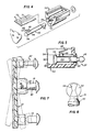
- an electrically operated adjustable mirror having a fixed base member 10 and a mirror case 12.
- the mirror case 12 has a mirror (unillustrated) mounted to one face and is pivotally connected on its opposite face to the base member 10. The details of the connection will be discussed in more detail below.
- the position of the mirror is adjusted about the base member 10 by a pair of adjustment shafts 14 which are pivotally received in sockets 15 protruding from the mirror case 12.
- Electric motor and gear means within member 10 operate to reciprocate adjustment shafts 14, and this reciprocal action pushes and pulls the mirror case 12 about the horizontal axis 16 and the vertical axis 18.
- a more detailed description of the adjustment shafts, motor means and gearing means may be found in applicant's United States Patent 4482211.
- the mirror case 12 is pivotally mounted to the base member 10 by a mounting means 19 comprising an elongate member 20 which extends outwardly from the base member 10 and has a sphere 22 affixed at its upper end.
- a sphere-receiving socket 24 extends outwardly from the mirror case 12, and has an opening 26 which leads into an interior spherical chamber 28 which is substantially the same size as the sphere 22.
- the opening 26 is slightly smaller in diameter than the sphere 22. The slightly smaller diameter of the opening 26 creates a retaining lip 30 which retains the sphere within socket 24.
- the mirror 12 is connected to the base member 10 by forcibly inserting the sphere 22 into the opening 26.
- the resilient yieldability of the plastic socket wall permits such insertion and subsequent retention.
- the yieldability may be increased by forming the socketwall in circumferentially spaced segments.
- the position of mirror case 12 is readily adjustable about the first and second pivotal axes 16 and 18.
- This limited freedom about third axis 32 provides stability without interfering with adjustment about the horizontal and vertical axes.
- the first means involves the location of two diametrically opposed grooves 34 on the sphere 22 which engage two splines 36 on the inside of socket 24. See Figures 8 and 9.
- the grooves 34 are flared at their ends to permit free pivotal action about the horizontal axis 16 and vertical axis 18 but are narrowed at their mid- point to prevent excessive pivoting about the third axis 32.
- the predetermined amount of pivotal movement about the third axes 32 is achieved by making the width of the splines 36 slightly less than the width of the groove 34 at its mid-point.
- An exemplary spacing which achieves the desired damping is 0,0008 mm (0,002") on each side of each spline 36 with a socket diameter 0,0165 mm (0,420").
- the second movement limiting means involves the use of a rollbar means 38 and stop means 40, as best shown in Figures 1, 2, 6 and 7.
- the rollbar means 38 is located on the mirror case 12 and comprises two elongated members extending outwardly from socket 24 in a direction perpendicular to the third axis 32 and parallel to the horizontal axis 16.
- the stop means 40 which for example may be paddle or peg shaped, extend outwardly from the base member 10 and are positioned a slight distance above or below and parallel to the horizontal axis 16 and on both sides of the mounting means 19.
- the roll bar means 38 may be on the base member 10 and the stop means 40 on the mirror case 12.
- the rollbar 38 When the mirror case 12 is connected to the base member 10 the rollbar 38 is a slight predetermined distance, for example 0,0004 mm (0,010 of an inch), above or below stop means 40, allowing limited pivotal movement about the third axis 32.
- the majority of the torsional vibrations of the vehicle to which the mirror is subjected are damped by the sphere 22 and socket 24 arrangement.
- the rollbar 38 and stop 40 arrangement is operable to engage just prior to when the splines and grooves engage so as to absorb peak loads such as when the vehicle wheel on the mirror side hits a pot hole. Shock absorbtion is achieved by deflection of the stop bars 40.
- the automatic adjustment means or "memory” feature will now be described.
- the linear potentiometers 42 Protruding outwardly from the base member 10 are the linear potentiometers 42, each comprising a shaft portion 44 and sphere portion 46 (see Figures 2 and 6).
- the spheres 46 are received within potentiometer receiving sockets 48 protruding from the mirror case 12.
- the shere 46 may be forceably inserted into the receiving socket 48.
- the sphere-socket connection causes potentiometer shaft 44 to reciprocate within a housing 50 as a result of the pivotal movement of the mirror case 12 about the base member 10.
- the housing 50 has an elongated bore 52 which is smooth to provide a surface on which the potentiometer shaft 44 can travel.
- An elongated opening or slot 54 is located in one side of bore 52.
- a guide means 56 is formed as a frustrum of a sphere at the end of the potentiometer shaft 44 opposite the sphere 46.
- Guide means 56 extends about the periphery of the potentiometer shaft 44 and has a cross sectional diameter slightly greater than that of shaft 44, permitting only the guide means to contact the interior walls 58 of the elongated bore 52.
- the guide means 56 has a convex outer surface to allow the potentiometer shaft 44 to readily rock within bore 52. Also, to provide clearance for the rocking action a gap 62 is provided between the housing 50 and potentiometer shaft 44.
- the ability of the potentiometer shaft 44 to rock within the elongated bore 52 is of critical importance to this invention. If the shaft 44 did not rock within the bore 52 the mirror could not pivot. As the mirror case 12 is pivoted about the base member 10 the sphere portion 46 of shaft 44 is moved in a arcuate path 64 as shown in Figure 6. This arcuate path causes the distance of potentiometer sphere 46 from the third pivotal axis 32 to continually change as the mirror moves.
- the potentiometer sphere 46 will be a maximum distance from the third pivotal axis 32 when the mirror case 12 is perpendicular to axis 32.
- the sphere will be a minimum distace from axis 32 when the mirror case 10 is either fully pivoted outwardly or fully pivoted inwardly with respect to the base member 10.
- the center line of the elongated bore 52 is initially positioned a distance from the third pivotal axis 32 which is between the maximum and minimum distances of the sphere from axis 32. Positioning the center line of the elongated bore 52 in this manner will reduce the required size of the gap 62 and reduce the extent of the resulting misalignment of shaft 44 within bore 52 as sphere 46 moves laterally with swinging socket 48.
- the centerline of the elongated bore 52 0,0344 mm (0,875 inches) from the center line of the third pivotal axis 32.
- the centerline of the sphere 46 is placed a distance 0,0347 mm (0,882 inches) from the center line of the third pivotal axis 32 when the mirror case 12 is parallel to the base member 10.
- the potentiometer sphere 46 is .868 inches from the third pivotal axis 32.
- the distance between the bore center line and the third pivotal axis is generally equal to the average of the maximum and minimum perpendicular distances of the sphere 46 center point from the third pivotal axis 32.
- the linear potentiometer shaft 44 has a tab member 66 extending outwardly therefrom and through the elongated opening 54 in the wall 58 of the elongated bore 52. Attached to the end of the tab 66 is a brush or wiper contact 68.
- the brush has two sides 65, 67 connected by a cross piece 69. Sides 65 and 67 contact a pair of spaced, parallel and stationary elongated electrically conductive resistance elements 70 and 71, respectively.
- the conductive element 70 is connected to a voltage source 80 such as the vehicle battery.
- a voltage source 80 such as the vehicle battery.
- potentiometer shaft 44 reciprocates within housing 50 the brush 68 moves along both conducting surfaces 70 and 71. This movement creates a variable electrical resistance on element 70 which generates an electrical signal proportionally responsive to the position of said mirror casing 12.
- This signal is carried by side 65 across member 69 to side 67 where it is received by the conductive element 71.
- a wire 73 attached to conductive element 71 carries the signal to a microprocessor 81.
- the vehicle operator adjusts the mirror casing to a desired position by using the manual switches 74 to actuate motors 82 (only one of which is shown) and adjustment shafts 14.
- the adjustment of the mirror case 12 generates an electrical signal across the linear potentiometer which is then received by the microprocessor 81.
- the operator pushes a set button 76, whereupon the microprocessor records the signal received.
- the microprocessor then starts the motors 82 which operate the actuators 14 to reposition the mirror.
- the motors continue to run as the linear potentiometers 42 sense the signal changes across element 70.
- the signal changes are continually received by the microprocessor 81 through element 71 and wire 73.
- the microprocessor compares the received signals with the recorded signal. When the linear potentiometers 42 reach the position having the identical signal as the recorded signal, the microprocessor immediately stops the motors 82.
- the mirror case 12 is now readjusted to the desired preset position.
- the mirror is readjustable to within 1/1000th of an inch of its previous position. It should be apparent to one of ordinary skill in the art that the microprocessor can store more than one signal (each signal representing one associated preset mirror position), one signal being used only for illustrative purposes.
- the mirror case 12 is easily removable from the base member by pulling each of the spheres out of the resiliently yieldable sockets in the mirror case. Therefore, repair of the electrically adjustable mirror is greatly simplified over those which are presently in use.
Landscapes
- Engineering & Computer Science (AREA)
- Multimedia (AREA)
- Mechanical Engineering (AREA)
- General Physics & Mathematics (AREA)
- Manufacturing & Machinery (AREA)
- Physics & Mathematics (AREA)
- Human Computer Interaction (AREA)
- Automation & Control Theory (AREA)
- Rear-View Mirror Devices That Are Mounted On The Exterior Of The Vehicle (AREA)
- Mirrors, Picture Frames, Photograph Stands, And Related Fastening Devices (AREA)
- Mounting And Adjusting Of Optical Elements (AREA)
- Control Of Position Or Direction (AREA)
- Polarising Elements (AREA)
- Selective Calling Equipment (AREA)
- Optical Elements Other Than Lenses (AREA)
Claims (11)
dadurch, daß besagte Sensoreinrichtung erste und zweite längliche Sensoreinheiten (44) aufweist, die beide ein erstes (46) und ein zweites Endstück (56) aufweisen,
Priority Applications (1)
| Application Number | Priority Date | Filing Date | Title |
|---|---|---|---|
| AT86104113T ATE54625T1 (de) | 1985-04-05 | 1986-03-25 | Speichereinstellvorrichtung fuer fernbedienbaren rueckblickspiegel. |
Applications Claiming Priority (2)
| Application Number | Priority Date | Filing Date | Title |
|---|---|---|---|
| US06/720,363 US4678295A (en) | 1985-04-05 | 1985-04-05 | Memory positioning system for remote control rear-view mirror |
| US720363 | 1985-04-05 |
Publications (3)
| Publication Number | Publication Date |
|---|---|
| EP0196608A2 EP0196608A2 (de) | 1986-10-08 |
| EP0196608A3 EP0196608A3 (en) | 1987-12-09 |
| EP0196608B1 true EP0196608B1 (de) | 1990-07-18 |
Family
ID=24893745
Family Applications (1)
| Application Number | Title | Priority Date | Filing Date |
|---|---|---|---|
| EP86104113A Expired - Lifetime EP0196608B1 (de) | 1985-04-05 | 1986-03-25 | Speichereinstellvorrichtung für fernbedienbaren Rückblickspiegel |
Country Status (9)
| Country | Link |
|---|---|
| US (1) | US4678295A (de) |
| EP (1) | EP0196608B1 (de) |
| JP (2) | JPS61295152A (de) |
| KR (1) | KR950002900B1 (de) |
| AT (1) | ATE54625T1 (de) |
| AU (1) | AU577508B2 (de) |
| BR (1) | BR8601565A (de) |
| CA (1) | CA1258391A (de) |
| DE (1) | DE3672644D1 (de) |
Families Citing this family (68)
| Publication number | Priority date | Publication date | Assignee | Title |
|---|---|---|---|---|
| GB8629826D0 (en) * | 1986-12-13 | 1987-01-21 | Britax Wingard Ltd | Rearview mirror |
| US4877214A (en) * | 1987-01-13 | 1989-10-31 | Murakami Kaimeido Co., Ltd. | Holding device of mirror element for rearview mirror |
| IT1208243B (it) * | 1987-02-11 | 1989-06-12 | Nardino Righi | Specchio retrovisore per autoveicoli |
| US4740068A (en) * | 1987-04-28 | 1988-04-26 | Magna International Inc. | Rearview mirror assembly with mounting arrangement including integrally molded dual axis pivot means |
| NZ224445A (en) * | 1987-05-04 | 1989-05-29 | Britax Rainsfords Pty Ltd | Frictional position maintaining device for adjustable rear vision mirror |
| JPS6447636A (en) * | 1987-05-04 | 1989-02-22 | Britax Rainsfords Pty Ltd | Controller for controlling direction of back-mirror |
| JPH0720858Y2 (ja) * | 1987-08-18 | 1995-05-15 | 市光工業株式会社 | パワ−ユニットの電線接続構造 |
| US4770522A (en) * | 1987-11-02 | 1988-09-13 | Siegel-Robert, Inc. | Automobile mirror position sensor and adjuster assembly |
| GB8802060D0 (en) * | 1988-01-29 | 1988-02-24 | Britax Geco Sa | Remotely controlled rear view mirror |
| US4915493A (en) * | 1989-01-04 | 1990-04-10 | Magna International Inc. | Automotive rear view mirror assembly |
| US5090797A (en) * | 1989-06-09 | 1992-02-25 | Lc Technologies Inc. | Method and apparatus for mirror control |
| US4929878A (en) * | 1989-06-27 | 1990-05-29 | United Technologies Automotive, Inc. | Memory mirror control system for vehicles and the like |
| EP0485620B1 (de) * | 1990-05-29 | 1995-10-11 | Ichikoh Industries Limited | Rückblickspiegel mit fernbedienung |
| US5126885A (en) * | 1990-06-18 | 1992-06-30 | Westech Innovations Inc. | Control device for electrically controlled rearview mirror |
| US5226034A (en) * | 1990-06-19 | 1993-07-06 | Ichikoh Industries, Ltd. | Electrically remote-controlled type mirror assembly |
| JPH0550881A (ja) * | 1991-08-19 | 1993-03-02 | Ichikoh Ind Ltd | 電動式リモートコントロールミラーおよびその制御回路 |
| US5467230A (en) * | 1993-08-16 | 1995-11-14 | Lowell Engineering Corp. | Dual pivoted member mount for mirror |
| US5477391A (en) * | 1993-08-16 | 1995-12-19 | Lowell Engineering Corp. | Mirror assembly movable into rearwardly folded position with reversing spring bias |
| US5477390A (en) * | 1993-08-16 | 1995-12-19 | Lowell Engineering Corp. | Mirror assembly powered into rearwardly folded position against reversing spring bias |
| US5436741A (en) * | 1993-12-28 | 1995-07-25 | Harman Automotive, Inc. | Holographic signaling mirror |
| DE29511817U1 (de) * | 1995-07-21 | 1996-11-14 | Robert Bosch Gmbh, 70469 Stuttgart | Vorrichtung zum Verstellen eines Kraftfahrzeugspiegels |
| AU5236598A (en) * | 1996-11-27 | 1998-06-22 | Borje A. Brandin | Mirror support orientation apparatus |
| US5838507A (en) * | 1996-12-19 | 1998-11-17 | Lowell Engineering Corporation | Mirror assembly with friction drive |
| US5900999A (en) * | 1997-01-09 | 1999-05-04 | Donnelly Corporation | Housing with integral electrical connectors for a rearview mirror actuator assembly |
| JP3396018B2 (ja) * | 1997-03-25 | 2003-04-14 | 株式会社村上開明堂 | ミラー位置検出装置 |
| DE29711539U1 (de) | 1997-07-03 | 1998-11-05 | Donnelly Hohe GmbH & Co. KG, 97903 Collenberg | Motorisch verstellbarer Fahrzeug-Rückspiegel |
| JP3343206B2 (ja) * | 1997-08-07 | 2002-11-11 | 株式会社東海理化電機製作所 | 自動車用ミラーアセンブリ |
| US5969870A (en) * | 1997-09-18 | 1999-10-19 | Anvik Corporation | Remotely adjustable, anti-glare vehicle mirror system |
| NL1010013C2 (nl) * | 1998-09-04 | 2000-03-07 | Iku Holding Montfoort Bv | Dempingsmechanisme voor een spiegel van een motorvoertuig. |
| US6755543B1 (en) * | 1998-11-02 | 2004-06-29 | Magna Mirror Systems Inc. | Coordinating pivoting and extending vehicle mirror |
| US6799856B2 (en) * | 2001-05-02 | 2004-10-05 | Magna Mirror Systems, Inc. | Coordinated pivoting and extending vehicle mirror |
| US6094027A (en) * | 1999-01-11 | 2000-07-25 | Donnelly Corporation | Vehicle memory mirror position transducer |
| EP1020328A3 (de) * | 1999-01-11 | 2003-04-02 | Donnelly Corporation | Verstellantrieb für einen Fahrzeugspiegel |
| US6213612B1 (en) | 1999-01-11 | 2001-04-10 | Donnelly Corporation | Mirror actuator electrical connector |
| DE19900987B4 (de) | 1999-01-13 | 2007-02-01 | Mekra Lang Gmbh & Co. Kg | Hornförmige Rückblickspiegelanordnung für Nutzfahrzeuge, insbesondere für Omnibusse |
| US6352231B1 (en) | 1999-04-30 | 2002-03-05 | Lang-Mekra North America, Llc | Clamping support for securing rearview mirrors on motor vehicles |
| DE19904778C2 (de) | 1999-02-05 | 2001-04-12 | Mekra Lang Gmbh & Co Kg | System zur automatischen Aussenspiegelverstellung bei Kurvenfahrten von Fahrzeugen |
| WO2000078572A1 (en) | 1999-06-21 | 2000-12-28 | Magna Mirror Systems Inc. | Extending and rotating rearview mirror assembly |
| US6474822B2 (en) * | 1999-07-14 | 2002-11-05 | David Swindon | Potentiometer for motorized mirror |
| US6412960B1 (en) | 1999-09-14 | 2002-07-02 | Kabushiki Kaisha Tokai-Rika-Denki-Seisakusho | Mirror surface angle adjusting device and mirror surface angle detector for a vehicle |
| AUPQ283499A0 (en) * | 1999-09-15 | 1999-10-07 | Britax Rainsfords Pty Ltd | A mirror mounting assembly for controlling vibration of a mirror |
| DE50103429D1 (de) * | 2001-03-12 | 2004-09-30 | Oechsler Ag | Motorische verschwenkeinrichtung für eine träger-platte insbesondere zur aufnahme eines kraftfahrzeugspiegels |
| DE20105791U1 (de) * | 2001-04-03 | 2002-08-14 | MEKRA Lang GmbH & Co. KG, 90765 Fürth | Spiegelanordnung für Kraftfahrzeuge |
| DE20106977U1 (de) | 2001-04-23 | 2002-08-29 | Mekra Lang Gmbh & Co Kg | Warneinrichtung in Kraftfahrzeugen |
| US7216996B2 (en) * | 2001-06-15 | 2007-05-15 | Schefenacker Vision Systems Uk Ltd. | Mirror with interchangeable appearance covers |
| JP4116866B2 (ja) * | 2002-11-13 | 2008-07-09 | 株式会社村上開明堂 | 電動リモコン鏡面調整装置 |
| JP4012460B2 (ja) * | 2002-11-28 | 2007-11-21 | 株式会社東海理化電機製作所 | 車両用アウタミラー装置 |
| US7370985B2 (en) * | 2002-12-30 | 2008-05-13 | Ian Boddy | Vehicular mirror with slip clutch for jack screw actuator |
| US20050032739A1 (en) * | 2003-06-30 | 2005-02-10 | David Gershon | Topical antiviral therapeutic and prophylactic treatment of adenoviruses and their associated diseases |
| EP1495912B1 (de) * | 2003-07-10 | 2009-03-25 | Ichikoh Industries, Ltd. | Vorrichtung zur Neigungsverstellung eines Aussenspiegels |
| KR100531313B1 (ko) * | 2004-03-15 | 2005-11-29 | 엘지전자 주식회사 | 영상표시장치용 스탠드 |
| JP4217187B2 (ja) * | 2004-04-07 | 2009-01-28 | 株式会社村上開明堂 | ミラー位置検出装置 |
| JP2006044511A (ja) * | 2004-08-05 | 2006-02-16 | Murakami Corp | ミラー及び角度検出装置 |
| JP2006096146A (ja) * | 2004-09-29 | 2006-04-13 | Murakami Corp | ミラー及び角度検出装置 |
| JP4395086B2 (ja) * | 2005-02-14 | 2010-01-06 | 株式会社ホンダロック | 車両用ミラー装置 |
| US7354170B2 (en) * | 2005-02-14 | 2008-04-08 | Kabushiki Kaisha Honda Lock | Vehicular mirror having tilt angle detection rod with swing axis |
| EP2253510B1 (de) * | 2009-05-19 | 2013-01-02 | SMR Patents S.à.r.l. | Modularer Rückspiegel und Montageverfahren dafür |
| US20110051268A1 (en) * | 2009-09-03 | 2011-03-03 | Patrick Martin | Blind spot mirror |
| US8783883B2 (en) * | 2010-08-30 | 2014-07-22 | Honda Motor Co., Ltd. | Method for controlling power to a motor in a vehicle door mirror |
| EP2517930B1 (de) * | 2011-04-28 | 2015-11-04 | Fico Mirrors, S.A. | Spiegelhalterung und Vorrichtung zur Anpassung der Ausrichtung des Spiegels |
| JPWO2017135106A1 (ja) * | 2016-02-04 | 2018-11-29 | 株式会社東海理化電機製作所 | 作動装置及び作動装置の製造方法 |
| DE102016108373A1 (de) * | 2016-05-04 | 2017-11-09 | SMR Patents S.à.r.l. | Positioniersystem für eine Rückblickanzeigevorrichtung |
| US10598924B2 (en) * | 2017-01-04 | 2020-03-24 | Ball Aerospace & Technologies Corp. | Cross flexure suspension system |
| DE102019105294B4 (de) | 2018-06-04 | 2021-06-10 | Motherson Innovations Company Limited | Rückblickaktuatormechanismus und Rückblickvorrichtung, die denselben nutzt |
| US10914339B2 (en) | 2018-09-25 | 2021-02-09 | Ball Aerospace & Technologies Corp. | Flexural pivot assembly with shaped blade sections |
| US12130423B1 (en) | 2020-08-12 | 2024-10-29 | Bae Systems Space & Mission Systems Inc. | Two degree-of freedom reactionless pointing and scanning system |
| US12320466B2 (en) | 2021-03-10 | 2025-06-03 | Bae Systems Space & Mission Systems Inc. | Systems and methods for limiting rotation of a supported object |
| US12313905B1 (en) | 2022-03-15 | 2025-05-27 | Bae Systems Space & Mission Systems Inc. | Monolithic two-axis flexure with center hole feature |
Family Cites Families (19)
| Publication number | Priority date | Publication date | Assignee | Title |
|---|---|---|---|---|
| US3549243A (en) * | 1968-11-08 | 1970-12-22 | Casco Products Corp | Remote control mirror |
| US3609014A (en) * | 1970-06-10 | 1971-09-28 | Kurz Arthur W Jun | Electric remote control rear view mirror |
| US3917212A (en) * | 1973-12-03 | 1975-11-04 | Harman Int Ind | Cross arm mirror mount for remote control rearview mirrors |
| US4056253A (en) * | 1974-05-16 | 1977-11-01 | Tenna Corporation | Adjustable mirror support |
| US3972597A (en) * | 1974-05-16 | 1976-08-03 | Tenna Corporation | Electrically adjustable vehicle rear view mirror |
| US4003271A (en) * | 1975-03-14 | 1977-01-18 | Keeler Brass Company | Mirror assembly |
| US4076392A (en) * | 1975-11-26 | 1978-02-28 | Murakami Kaimedio Co., Ltd. | Remotely controllable rear view mirror |
| FR2385137A1 (fr) * | 1977-03-24 | 1978-10-20 | Seim | Dispositif de reglage electrique d'un element tel qu'un retroviseur exterieur d'un vehicule automobile |
| DE2840789A1 (de) * | 1978-09-20 | 1980-04-03 | Weiss Paul Fa | Elektromotorisch verstellbarer spiegel |
| DE2937961C2 (de) * | 1978-09-27 | 1983-07-21 | Murakami Kaimeido Co., Ltd., Shizuoka | Vorrichtung zum Verstellen eines Spiegelglasträgers eines Kraftfahrzeugrückspiegels |
| DE3043594A1 (de) * | 1980-11-19 | 1982-08-19 | Efrudec GmbH, 7141 Schwieberdingen | Elektromotorisch verstellbarer rueckblickspiegel |
| JPS5790236A (en) * | 1980-11-25 | 1982-06-04 | Nippon Denso Co Ltd | Car driving control device |
| DE3204791C1 (de) * | 1982-02-11 | 1983-10-06 | Daimler Benz Ag | Servomotorisch einstellbarer Aussenspiegel fuer Fahrzeuge |
| DE3213694A1 (de) * | 1982-04-14 | 1983-10-27 | Bernhard Mittelhaeuser | Rueckblickspiegel fuer fahrzeuge |
| FR2526737B1 (fr) * | 1982-05-13 | 1986-04-25 | Manzoni Stephane | Dispositif limiteur de couple pour mecanisme de commande d'un miroir de retroviseur |
| JPS592952A (ja) * | 1982-06-28 | 1984-01-09 | Tokai Rika Co Ltd | バツクミラ−のメモリ−リセツト装置 |
| US4482211A (en) * | 1982-12-13 | 1984-11-13 | Robert J. Fisher | Electrically operated remote control rearview mirror |
| DE3311229A1 (de) * | 1983-03-28 | 1984-10-04 | Vdo Adolf Schindling Ag, 6000 Frankfurt | Einrichtung zum verstellen eines gegenstandes in fahrzeugen, insbesondere eines rueckspiegels |
| JPS59230840A (ja) * | 1983-06-14 | 1984-12-25 | Matsuyama Seisakusho:Kk | 電動式バツクミラ−の角度検出装置 |
-
1985
- 1985-04-05 US US06/720,363 patent/US4678295A/en not_active Expired - Fee Related
-
1986
- 1986-02-21 CA CA000502488A patent/CA1258391A/en not_active Expired
- 1986-03-25 DE DE8686104113T patent/DE3672644D1/de not_active Expired - Fee Related
- 1986-03-25 EP EP86104113A patent/EP0196608B1/de not_active Expired - Lifetime
- 1986-03-25 AT AT86104113T patent/ATE54625T1/de not_active IP Right Cessation
- 1986-03-26 AU AU55537/86A patent/AU577508B2/en not_active Ceased
- 1986-04-04 KR KR1019860002553A patent/KR950002900B1/ko not_active Expired - Fee Related
- 1986-04-04 JP JP61076872A patent/JPS61295152A/ja active Pending
- 1986-04-04 BR BR8601565A patent/BR8601565A/pt not_active IP Right Cessation
-
1994
- 1994-04-18 JP JP1994004032U patent/JP2589769Y2/ja not_active Expired - Lifetime
Also Published As
| Publication number | Publication date |
|---|---|
| JP2589769Y2 (ja) | 1999-02-03 |
| BR8601565A (pt) | 1986-12-09 |
| EP0196608A2 (de) | 1986-10-08 |
| ATE54625T1 (de) | 1990-08-15 |
| AU577508B2 (en) | 1988-09-22 |
| US4678295A (en) | 1987-07-07 |
| KR950002900B1 (ko) | 1995-03-28 |
| CA1258391A (en) | 1989-08-15 |
| DE3672644D1 (de) | 1990-08-23 |
| JPS61295152A (ja) | 1986-12-25 |
| JPH0681834U (ja) | 1994-11-22 |
| EP0196608A3 (en) | 1987-12-09 |
| AU5553786A (en) | 1986-10-09 |
| KR860008485A (ko) | 1986-11-15 |
Similar Documents
| Publication | Publication Date | Title |
|---|---|---|
| EP0196608B1 (de) | Speichereinstellvorrichtung für fernbedienbaren Rückblickspiegel | |
| EP0085737B1 (de) | Einrichtung eines Spiegels mit elektrischer Fernbedienung | |
| US5033835A (en) | Remote control mirror with angular viewing adjustments | |
| US4696555A (en) | Electric remote control mirror apparatus | |
| US5050977A (en) | Automotive vehicle mirror with gauging viewing mirror portion | |
| EP0528418B1 (de) | Elektrische ferngesteuerte Spiegeleinrichtung | |
| EP0410587A2 (de) | Fahrzeugaussenspiegel | |
| US5226034A (en) | Electrically remote-controlled type mirror assembly | |
| US4572626A (en) | Electric remote control back-mirror assembly | |
| EP1279557A2 (de) | Fernbedienbarer Fahrzeugrückblickspiegel | |
| EP0064335B1 (de) | Rückblickspiegel für Kraftfahrzeuge | |
| US5760977A (en) | Exterior rearview mirror for motor vehicles | |
| US7354170B2 (en) | Vehicular mirror having tilt angle detection rod with swing axis | |
| EP0074753A1 (de) | Rückspiegel für Kraftfahrzeuge | |
| CA2337974C (en) | External rearview mirror | |
| EP0186366A2 (de) | Rückblickspiegel für Fahrzeuge | |
| EP0463563A1 (de) | Elektrisch fernbedienbarer Rückspiegel | |
| US4519677A (en) | Power-operated vehicle mirror | |
| US4577823A (en) | Device for remotely controlling a rearview mirror | |
| JPS6037856Y2 (ja) | 自動車用ミラ−装置 | |
| JP3482839B2 (ja) | 車両ミラー用ワイパー | |
| JPH028835Y2 (de) | ||
| US6443607B1 (en) | Headlamp adjusting attachment nut | |
| JPS6361218B2 (de) | ||
| JPH11165589A (ja) | 車両ミラー用ワイパー |
Legal Events
| Date | Code | Title | Description |
|---|---|---|---|
| PUAI | Public reference made under article 153(3) epc to a published international application that has entered the european phase |
Free format text: ORIGINAL CODE: 0009012 |
|
| AK | Designated contracting states |
Kind code of ref document: A2 Designated state(s): AT BE CH DE FR GB IT LI LU NL SE |
|
| PUAL | Search report despatched |
Free format text: ORIGINAL CODE: 0009013 |
|
| AK | Designated contracting states |
Kind code of ref document: A3 Designated state(s): AT BE CH DE FR GB IT LI LU NL SE |
|
| 17P | Request for examination filed |
Effective date: 19880513 |
|
| 17Q | First examination report despatched |
Effective date: 19881021 |
|
| ITF | It: translation for a ep patent filed | ||
| GRAA | (expected) grant |
Free format text: ORIGINAL CODE: 0009210 |
|
| AK | Designated contracting states |
Kind code of ref document: B1 Designated state(s): AT BE CH DE FR GB IT LI LU NL SE |
|
| PG25 | Lapsed in a contracting state [announced via postgrant information from national office to epo] |
Ref country code: SE Effective date: 19900718 Ref country code: LI Effective date: 19900718 Ref country code: CH Effective date: 19900718 Ref country code: BE Effective date: 19900718 |
|
| REF | Corresponds to: |
Ref document number: 54625 Country of ref document: AT Date of ref document: 19900815 Kind code of ref document: T |
|
| ET | Fr: translation filed | ||
| REF | Corresponds to: |
Ref document number: 3672644 Country of ref document: DE Date of ref document: 19900823 |
|
| REG | Reference to a national code |
Ref country code: CH Ref legal event code: PL |
|
| ITTA | It: last paid annual fee | ||
| PG25 | Lapsed in a contracting state [announced via postgrant information from national office to epo] |
Ref country code: LU Free format text: LAPSE BECAUSE OF NON-PAYMENT OF DUE FEES Effective date: 19910331 |
|
| PLBE | No opposition filed within time limit |
Free format text: ORIGINAL CODE: 0009261 |
|
| STAA | Information on the status of an ep patent application or granted ep patent |
Free format text: STATUS: NO OPPOSITION FILED WITHIN TIME LIMIT |
|
| 26N | No opposition filed | ||
| NLS | Nl: assignments of ep-patents |
Owner name: LOWELL ENGINEERING CORPORATION TE PALO ALTO, MICHI |
|
| REG | Reference to a national code |
Ref country code: FR Ref legal event code: TP |
|
| ITPR | It: changes in ownership of a european patent |
Owner name: ASSUNZIONE O VARIAZIONE MANDATO;UFFICIO MARCHI & M |
|
| REG | Reference to a national code |
Ref country code: GB Ref legal event code: 732 |
|
| REG | Reference to a national code |
Ref country code: GB Ref legal event code: IF02 |
|
| PGFP | Annual fee paid to national office [announced via postgrant information from national office to epo] |
Ref country code: FR Payment date: 20040309 Year of fee payment: 19 |
|
| PGFP | Annual fee paid to national office [announced via postgrant information from national office to epo] |
Ref country code: NL Payment date: 20040310 Year of fee payment: 19 |
|
| PGFP | Annual fee paid to national office [announced via postgrant information from national office to epo] |
Ref country code: AT Payment date: 20040311 Year of fee payment: 19 |
|
| PGFP | Annual fee paid to national office [announced via postgrant information from national office to epo] |
Ref country code: GB Payment date: 20040324 Year of fee payment: 19 |
|
| PGFP | Annual fee paid to national office [announced via postgrant information from national office to epo] |
Ref country code: DE Payment date: 20040401 Year of fee payment: 19 |
|
| PG25 | Lapsed in a contracting state [announced via postgrant information from national office to epo] |
Ref country code: IT Free format text: LAPSE BECAUSE OF NON-PAYMENT OF DUE FEES;WARNING: LAPSES OF ITALIAN PATENTS WITH EFFECTIVE DATE BEFORE 2007 MAY HAVE OCCURRED AT ANY TIME BEFORE 2007. THE CORRECT EFFECTIVE DATE MAY BE DIFFERENT FROM THE ONE RECORDED. Effective date: 20050325 Ref country code: GB Free format text: LAPSE BECAUSE OF NON-PAYMENT OF DUE FEES Effective date: 20050325 Ref country code: AT Free format text: LAPSE BECAUSE OF NON-PAYMENT OF DUE FEES Effective date: 20050325 |
|
| PG25 | Lapsed in a contracting state [announced via postgrant information from national office to epo] |
Ref country code: NL Free format text: LAPSE BECAUSE OF NON-PAYMENT OF DUE FEES Effective date: 20051001 Ref country code: DE Free format text: LAPSE BECAUSE OF NON-PAYMENT OF DUE FEES Effective date: 20051001 |
|
| GBPC | Gb: european patent ceased through non-payment of renewal fee |
Effective date: 20050325 |
|
| PG25 | Lapsed in a contracting state [announced via postgrant information from national office to epo] |
Ref country code: FR Free format text: LAPSE BECAUSE OF NON-PAYMENT OF DUE FEES Effective date: 20051130 |
|
| NLV4 | Nl: lapsed or anulled due to non-payment of the annual fee |
Effective date: 20051001 |
|
| REG | Reference to a national code |
Ref country code: FR Ref legal event code: ST Effective date: 20051130 |