EP0196793B1 - Raumfahrzeug in Modulbauweise - Google Patents
Raumfahrzeug in Modulbauweise Download PDFInfo
- Publication number
- EP0196793B1 EP0196793B1 EP86301555A EP86301555A EP0196793B1 EP 0196793 B1 EP0196793 B1 EP 0196793B1 EP 86301555 A EP86301555 A EP 86301555A EP 86301555 A EP86301555 A EP 86301555A EP 0196793 B1 EP0196793 B1 EP 0196793B1
- Authority
- EP
- European Patent Office
- Prior art keywords
- spacecraft
- module
- modules
- modular
- solar
- Prior art date
- Legal status (The legal status is an assumption and is not a legal conclusion. Google has not performed a legal analysis and makes no representation as to the accuracy of the status listed.)
- Expired - Lifetime
Links
Images


Classifications
-
- B—PERFORMING OPERATIONS; TRANSPORTING
- B64—AIRCRAFT; AVIATION; COSMONAUTICS
- B64G—COSMONAUTICS; VEHICLES OR EQUIPMENT THEREFOR
- B64G1/00—Cosmonautic vehicles
- B64G1/22—Parts of, or equipment specially adapted for fitting in or to, cosmonautic vehicles
- B64G1/64—Systems for coupling or separating cosmonautic vehicles or parts thereof, e.g. docking arrangements
- B64G1/641—Interstage or payload connectors
-
- B—PERFORMING OPERATIONS; TRANSPORTING
- B64—AIRCRAFT; AVIATION; COSMONAUTICS
- B64G—COSMONAUTICS; VEHICLES OR EQUIPMENT THEREFOR
- B64G1/00—Cosmonautic vehicles
- B64G1/10—Artificial satellites; Systems of such satellites; Interplanetary vehicles
- B64G1/12—Artificial satellites; Systems of such satellites; Interplanetary vehicles manned
-
- B—PERFORMING OPERATIONS; TRANSPORTING
- B64—AIRCRAFT; AVIATION; COSMONAUTICS
- B64G—COSMONAUTICS; VEHICLES OR EQUIPMENT THEREFOR
- B64G1/00—Cosmonautic vehicles
- B64G1/22—Parts of, or equipment specially adapted for fitting in or to, cosmonautic vehicles
- B64G1/223—Modular spacecraft systems
-
- B—PERFORMING OPERATIONS; TRANSPORTING
- B64—AIRCRAFT; AVIATION; COSMONAUTICS
- B64G—COSMONAUTICS; VEHICLES OR EQUIPMENT THEREFOR
- B64G1/00—Cosmonautic vehicles
- B64G1/002—Launch systems
- B64G1/006—Reusable launch rockets or boosters
-
- B—PERFORMING OPERATIONS; TRANSPORTING
- B64—AIRCRAFT; AVIATION; COSMONAUTICS
- B64G—COSMONAUTICS; VEHICLES OR EQUIPMENT THEREFOR
- B64G1/00—Cosmonautic vehicles
- B64G1/14—Space shuttles
-
- B—PERFORMING OPERATIONS; TRANSPORTING
- B64—AIRCRAFT; AVIATION; COSMONAUTICS
- B64G—COSMONAUTICS; VEHICLES OR EQUIPMENT THEREFOR
- B64G1/00—Cosmonautic vehicles
- B64G1/22—Parts of, or equipment specially adapted for fitting in or to, cosmonautic vehicles
- B64G1/222—Parts of, or equipment specially adapted for fitting in or to, cosmonautic vehicles for deploying structures between a stowed and deployed state
- B64G1/2221—Parts of, or equipment specially adapted for fitting in or to, cosmonautic vehicles for deploying structures between a stowed and deployed state characterised by the manner of deployment
- B64G1/2222—Folding
- B64G1/2223—Folding via scissor linkage
-
- B—PERFORMING OPERATIONS; TRANSPORTING
- B64—AIRCRAFT; AVIATION; COSMONAUTICS
- B64G—COSMONAUTICS; VEHICLES OR EQUIPMENT THEREFOR
- B64G1/00—Cosmonautic vehicles
- B64G1/22—Parts of, or equipment specially adapted for fitting in or to, cosmonautic vehicles
- B64G1/42—Arrangements or adaptations of power supply systems
- B64G1/44—Arrangements or adaptations of power supply systems using radiation, e.g. deployable solar arrays
-
- Y—GENERAL TAGGING OF NEW TECHNOLOGICAL DEVELOPMENTS; GENERAL TAGGING OF CROSS-SECTIONAL TECHNOLOGIES SPANNING OVER SEVERAL SECTIONS OF THE IPC; TECHNICAL SUBJECTS COVERED BY FORMER USPC CROSS-REFERENCE ART COLLECTIONS [XRACs] AND DIGESTS
- Y10—TECHNICAL SUBJECTS COVERED BY FORMER USPC
- Y10S—TECHNICAL SUBJECTS COVERED BY FORMER USPC CROSS-REFERENCE ART COLLECTIONS [XRACs] AND DIGESTS
- Y10S136/00—Batteries: thermoelectric and photoelectric
- Y10S136/291—Applications
- Y10S136/292—Space - satellite
Definitions
- This invention relates to a modular spacecraft system formed by connecting substantially identical spacecraft modules, and to the construction of the individual spacecraft modules used to assemble the modular spacecraft system.
- the invention further relates to a method for deployment of the spacecraft modules and to a method for assembly of the modular spacecraft system.
- a specific module might contain equipment, such as solar collection devices, antennas and other communications equipment, or other hardware and subsystems required for operation of the spacecraft, such as attitude and orbit control devices or tracking, telemetry and command equipment.
- This flight mode is preferred when it is desired to obtain maximum power from the solar arrays 44, 46 for use by the materials processing payloads of the facility module 22, since in this orientation the arrays can be made to face directly toward the sun at all points in the sunlit portion of the spacecraft orbit with only occasional and minor adjustment of the solar array gimbals.
- the gravity gradient boom 58 may be partially extended during quasi sun-oriented orbital flight in order to cause the two orbital-plane moments of inertia of the spacecraft 20 to be made substantially equal. This allows the spacecraft to be made neutrally stable in the orbital plane, and thus requires a minimum amount of active attitude control to maintain the spacecraft in the desired orientation. Such a capability is particularly desirable in the case of a spacecraft 20 of the type described herein, in which different types of supply modules 24 will be used to support different types of materials processing payloads in the facility module 22.
- the supply modules may have different sizes and masses and may therefore have the effect of changing the moments of inertia of the spacecraft 20.
- the outer shell 62 of the facility module is generally cylindrical in shape with planar or flattened portions 32, 34 extending vertically on each side as described previously.
- the outer shell 62 serves as a thermal and meteorite shield for the facility module and also contains integral coolant passages and manifolds allowing it to serve as a heat radiator for dissipating heat generated by the operation of the facility module and its payloads.
- the radiator skin is preferably pierced by a regular pattern of holes (not shown) to allow temporary or permanent attachment of mobility and restraint aids or external appertenances during extra-vehicular activity (EVA) by the Shuttle crew.
- the interior of the supply module 24 includes a small pressurizable chamber 114 that communicates with the berthing mechanism 104 so as to be accessible from the interior of the facility module 22 when the two modules are coupled together.
- the berthing mechanism 104 of the supply module 24 connects to the lower berthing mechanism 76 of the facility module 22, and fluid and electrical connections between the two modules are made by manually connected jumper lines (not shown).
- the pressurizable chamber 114 facilitates the manual connection of these lines by the Shuttle crew.
- the grapple fitting 27 allows the supply module 24 to be engaged by the Shuttle RMS and is mounted in a recessed position with respect to the outer shell 102 of the supply module, similar to the manner in which the grapple fittings 26 of the facility module 22 are installed.
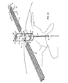
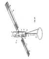
- the deployment sequence begins with a 90° rotation of the array 44 and canister 92 about the inboard gimbal 80, causing the array to emerge from the external payload area through the door 48 of Fig. 1A.
- the array 44 and canister 92 then rotate 90° about the second gimbal 82 in order to align the canister in an outwardly facing position with respect to the facility module 22. This corresponds to the intermediate position 44" of the array in Fig. 4.
- the next deployment step consists of a 90° rotation of the array with respect to the canister 92, in order to orient the array so that it will unfurl as described in the next step of deployment. This rotation occurs only during the initial deployment sequence and does not occur again during normal operation of the array.
- the next deployment step consists of the extension of the coilable mast 96 from the canister 92, which causes the array to unfurl in an accordian-like manner in a direction away from the facility module 22. This is followed by a rotation of 180° about the outboard gimbal 84 in order to place the array in the solid line position 44 of Fig. 4, that is, with the solar collecting surfaces of the array facing upwardly and the coilable mast on the underside of the array.
- the array 44 is in its fully deployed position, a further 90° rotation about the central gimbal 82 is carried out to bring the array to the phantom position 44'" of Fig. 4. This is done to facilitate orbital emplacement of the spacecraft 20 from the Shuttle vehicle.
- the spacecraft 20 is berthed to the Shuttle during initial deployment by means of the upper berthing mechanism 28 of the facility module 22, and, as a result, the berthed spacecraft 20 is oriented with the supply module end facing away from the Shuttle. In the phantom position 44' ' ', the array is also facing in this direction.
- the array 44 is periodically rotated about the outboard gimbal 84 to achieve solar tracking. While it is sometimes useful to combine these rotations with rotations about the central gimbal 82 to improve solar tracking, this is ordinarily not necessary.
- An additional use of the central gimbal 82, after initial deployment of the solar arrays, is to pivot the arrays to a protected position during Shuttle berthing.
- the inboard gimbal 80 is used to move the solar arrays out of the way during supply module changeout, and is also used to prevent interference between the arrays of coupled spacecraft during modular expansion as will now be described with reference to Figs. 5 and 6.
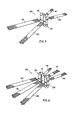
- Fig. 5 illustrates a modular spacecraft system 250 consisting of two identical spacecraft modules 20, 220 of the type described above.
- the two spacecraft modules are joined by their berthing mechanisms 36 (shown in Fig. 1), thereby forming a side-to-side connection as shown.
- the eccentric inner hulls 66 of the two spacecraft are closest to each other. Fluid and electrical lines are established between the two spacecraft in the vestibule area between the coupled berthing mechanisms as described earlier.
- the adjoining pairs of solar arrays 44, 246 and 46, 244 of the spacecraft modules 20, 220 are rotated in opposite directions about their inboard gimbals 80 in order to produce an angular spread or spacing between the arrays. This avoids mechanical interference between the adjoining arrays an also prevents one array from significantly occluding the other with respect to incident solar radiation.
- Fig. 6 illustrates a modular spacecraft system 350 consisting of three identical spacecraft modules 20, 220 and 320.
- the first two spacecraft modules 20, 220 are joined in the same way as shown in Fig. 5.
- the third spacecraft module 320 is joined by its berthing mechanism 36 to the second berthing mechanism 38 of the first spacecraft module 20, and thus has its pressure hull 66 in physical communication with those of the first two spacecraft modules 20, 220. Fluid and electrical connections may be established between the third module 320 and the first module 20 in the vestibule area between their respective berthing mechanisms.
- interference between adjoining solar arrays is avoided by rotating the arrays 244, 346 and 246, 344 in opposite directions about their inboard gimbals 80 as shown.
- the arrays 44, 46 of the first spacecraft module 20 occupy a central position between those of the second and third modules and hence do not require this rotation to provide clearance.
- the two-module and three-module systems of Figs. 5 and 6, respectively, provide an increased material processing capability as well as increased generation of electrical power from the additional sets of solar arrays. Hence it is possible to carry out materials procesing operations on as large or small a scale as desired, merely by combining different numbers of modules.
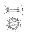
- Fig. 7 is an elevational view of the berthing mechanism 36 of the spacecraft 20.
- the remaining berthing mechanisms 28, 38, 76 and 104 will be understood to be identical in construction.
- the berthing mechanisms are androgynous in the sense that the principal functions of berthing can be carried out by any two mechanisms without such mechanisms being required to be matched pairs.
- the berthing mechanism 36 includes a rim 130 carrying four equally spaced alignment guides 132 to allow berthing in clocking increments of 90°.
- the rim 130 also carries eight equally spaced structural latches 134 which operate according to the latch-on-latch concept; that is, the extended latches of one mechanism engage the retracted latches of the other when the two mechanisms are within a certain distance from each other. Separate capture latches may be employed, if desired, but are not illustrated in the drawings.
- the hatch closure 77 is retained within the rim 130 beind a lip 136.
- the hatch closure may be provided with a viewport (not shown
- Fig. 8 is a sectional view illustrating the berthing mechanism 36 coupled to an identical berthing mechanism (shown in phantom) of another spacecraft. Engagement between the two berthing mechanisms is accomplished without discrete impact attenuation devices. Two concentric seals 138 are carried by each berthing mechanism, and the seals bear against each other to form an airtight connection between the spacecraft. Fluid and/or electrical connections between spacecraft are made manually by "jumpers" passing through the vestibule area between berthing mechanisms.
- the jumper line 140 connects fluid and/or electrical lines which are external to the two spacecraft, while the jumper line 142 connects fluid and/or electerical lines which are internal to the two spacecraft.
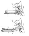
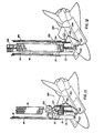
- Shuttle RMS 206 then attaches to grapple fitting 227 on second supply module 224, extracts the supply module 224 form the cargo bay 204, and connects berthing mechanism 225 on supply module 224 to berthing mechanism 276 on facility module 222.
- Solar array 46 is shown partially cut away so that the berthing of the supply module can be better seen.
Landscapes
- Engineering & Computer Science (AREA)
- Remote Sensing (AREA)
- Aviation & Aerospace Engineering (AREA)
- Physics & Mathematics (AREA)
- Astronomy & Astrophysics (AREA)
- General Physics & Mathematics (AREA)
- Photovoltaic Devices (AREA)
- Control Of Position, Course, Altitude, Or Attitude Of Moving Bodies (AREA)
- Steering Devices For Bicycles And Motorcycles (AREA)
- Electrophonic Musical Instruments (AREA)
- Body Structure For Vehicles (AREA)
Claims (7)
Priority Applications (1)
| Application Number | Priority Date | Filing Date | Title |
|---|---|---|---|
| AT86301555T ATE57350T1 (de) | 1985-03-20 | 1986-03-05 | Raumfahrzeug in modulbauweise. |
Applications Claiming Priority (2)
| Application Number | Priority Date | Filing Date | Title |
|---|---|---|---|
| US713817 | 1985-03-20 | ||
| US06/713,817 US4834325A (en) | 1985-03-20 | 1985-03-20 | Modular spacecraft system |
Publications (2)
| Publication Number | Publication Date |
|---|---|
| EP0196793A1 EP0196793A1 (de) | 1986-10-08 |
| EP0196793B1 true EP0196793B1 (de) | 1990-10-10 |
Family
ID=24867661
Family Applications (1)
| Application Number | Title | Priority Date | Filing Date |
|---|---|---|---|
| EP86301555A Expired - Lifetime EP0196793B1 (de) | 1985-03-20 | 1986-03-05 | Raumfahrzeug in Modulbauweise |
Country Status (6)
| Country | Link |
|---|---|
| US (1) | US4834325A (de) |
| EP (1) | EP0196793B1 (de) |
| JP (1) | JPH0729640B2 (de) |
| AT (1) | ATE57350T1 (de) |
| CA (1) | CA1282767C (de) |
| DE (1) | DE3674822D1 (de) |
Families Citing this family (56)
| Publication number | Priority date | Publication date | Assignee | Title |
|---|---|---|---|---|
| US4872625A (en) * | 1984-07-30 | 1989-10-10 | Filley Charles C | Universal module assembly for space structures |
| WO1990001447A1 (fr) * | 1988-08-12 | 1990-02-22 | Nippon Telegraph And Telephone Corporation | Procede et appareil de modification d'orbite d'un satellite artificiel |
| US4949922A (en) * | 1988-12-09 | 1990-08-21 | Hughes Aircraft Company | Satellite control system |
| US5271582A (en) * | 1990-06-29 | 1993-12-21 | Standard Space Platforms Corp. | Modular mother satellite bus for subsidiary payloads |
| US5152482A (en) * | 1990-06-29 | 1992-10-06 | Standard Space Platforms Corp. | Modular mother satellite bus for subsidiary payloads |
| FR2669887B1 (fr) * | 1990-11-30 | 1995-06-02 | Aerospatiale | Procede de controle d'attitude en tangage d'un satellite grace a la pression de radiation solaire et satellite adapte a sa mise en óoeuvre. |
| US5228644A (en) * | 1991-05-28 | 1993-07-20 | The United States Of America As Represented By The United States National Aeronautics And Space Administration | Solar powered system for a space vehicle |
| US5145130A (en) * | 1991-10-23 | 1992-09-08 | The United States Of America As Represented By The Administrator Of The National Aeronautics & Space Administration | Robot serviced space facility |
| EP0541052B1 (de) * | 1991-11-05 | 1996-02-07 | Hitachi, Ltd. | System von Raumfahrzeugen |
| US5310144A (en) * | 1992-07-06 | 1994-05-10 | Hughes Aircraft Company | Method and apparatus for satellite torque balancing |
| WO1994006680A1 (en) * | 1992-09-23 | 1994-03-31 | Space Industries, Inc. | Spacecraft berthing mechanism |
| US5441221A (en) * | 1993-12-03 | 1995-08-15 | The United States Of America As Represented By The Administrator Of The National Aeronautics And Space Administration | Heavy-lift vehicle-launched space station method and apparatus |
| US5522569A (en) * | 1994-02-04 | 1996-06-04 | Orbital Sciences Corporation | Satellite having a stackable configuration |
| US5669586A (en) * | 1994-12-06 | 1997-09-23 | Space Systems/Loral, Inc. | Satellite gravity gradient compensation using on-orbit solar array reorientation |
| US5806799A (en) * | 1995-03-09 | 1998-09-15 | Spacehab, Inc. | Variable length mission-configurable module for space transportation vehicle |
| US5833175A (en) * | 1995-12-22 | 1998-11-10 | Hughes Electronics Corporation | Spacecraft with large east-west dimensions |
| US5779195A (en) * | 1996-05-03 | 1998-07-14 | Motorola, Inc. | Satellite assembly having modular common bus components |
| US5848766A (en) * | 1996-06-18 | 1998-12-15 | Spacehab, Inc. | Integrated cargo carrier for space applications |
| US6068218A (en) * | 1997-05-14 | 2000-05-30 | Hughes Electronics Corporation | Agile, spinning spacecraft with sun-steerable solar cell array and method |
| DE19745981B4 (de) * | 1997-10-17 | 2012-09-27 | Peter Maagh | Reaktionsmischung mit mehreren Komponenten zur Abdichtung von Rohrverbindungen sowie deren Verwendung |
| US6513760B1 (en) * | 1999-12-14 | 2003-02-04 | Kistler Aerospace Corporation | Logistics module system and method |
| US6481671B1 (en) | 2000-08-14 | 2002-11-19 | Ball Aerospace & Technologies Corp. | Spacecraft sunshield for use in performing solar torque balancing |
| US6581883B2 (en) * | 2001-07-13 | 2003-06-24 | The Boeing Company | Extendable/retractable bi-fold solar array |
| US6945500B2 (en) * | 2003-08-15 | 2005-09-20 | Skycorp, Inc. | Apparatus for a geosynchronous life extension spacecraft |
| US7988096B2 (en) * | 2004-09-01 | 2011-08-02 | Humphries Peter J | Space manufacturing module system and method |
| US7874520B2 (en) * | 2006-03-21 | 2011-01-25 | Lockheed Martin Corporation | Satellite with deployable, articulatable thermal radiators |
| WO2008088311A2 (en) * | 2006-12-28 | 2008-07-24 | Bosley Brian W | Solar panel mounting apparatus with a plurality of independtently adjustable arms and rotatable vertical axis |
| EP2377164A4 (de) * | 2008-12-08 | 2013-07-10 | Mark C Anderson | Sonnenenergieumwandlungsartikel sowie verfahren zu ihrer herstellung und verwendung |
| WO2010126604A2 (en) * | 2009-04-30 | 2010-11-04 | Tethers Unlimited, Inc. | Terminator tape satellite deorbit module |
| JP5586012B2 (ja) * | 2010-05-14 | 2014-09-10 | 独立行政法人 宇宙航空研究開発機構 | 衛星システム |
| FR2979616A1 (fr) * | 2011-09-07 | 2013-03-08 | Stephane Raphael Teboul | Dispositif de satellite permettant de mettre en oeuvre une partie de la structure d'une station spatiale |
| RU2535979C2 (ru) * | 2012-12-04 | 2014-12-20 | Открытое акционерное общество "Информационные спутниковые системы" имени академика М.Ф. Решетнёва" | Система ориентации навигационного спутника |
| US9434485B1 (en) | 2013-01-25 | 2016-09-06 | Stephen C. Lehocki | Multi-purpose cargo delivery and space debris removal system |
| US9284073B2 (en) * | 2013-07-08 | 2016-03-15 | Bigelow Aerospace | Standard transit tug |
| US9284069B2 (en) * | 2013-07-08 | 2016-03-15 | Bigelow Aerospace | Solar generator tug |
| US9567116B2 (en) * | 2013-07-08 | 2017-02-14 | Bigelow Aerospace | Docking node transporter tug |
| US9463883B2 (en) * | 2013-08-22 | 2016-10-11 | Bigelow Aerospace, LLC | Spacecraft capture tug |
| USD756887S1 (en) * | 2013-12-20 | 2016-05-24 | Andrew Simon Filo | Cubesat with a chipsat deployer |
| USD748037S1 (en) * | 2013-12-22 | 2016-01-26 | Andrew Simon Filo | Self-propelled and spin stabilized fempto satellite with a dual asymmetrical bifurcated dipole antennae kicker |
| JP6448293B2 (ja) * | 2014-03-05 | 2019-01-09 | ザ・ボーイング・カンパニーThe Boeing Company | 構造部材展開システム |
| USD756886S1 (en) * | 2014-03-18 | 2016-05-24 | Planetary Resources Development Corp. | Spacecraft system |
| DE102014104695A1 (de) | 2014-04-02 | 2015-10-08 | Rheinisch-Westfälische Technische Hochschule (Rwth) Aachen | Androgyne Kopplungseinrichtung zur Verbindung von Modulen sowie entsprechende Module |
| US9404256B2 (en) * | 2014-04-08 | 2016-08-02 | Composite Technology Development, Inc. | Stowage and deployment of slit tube booms |
| RU2569999C2 (ru) * | 2014-04-29 | 2015-12-10 | Акционерное общество "Информационные спутниковые системы" имени академика М.Ф. Решетнёва" | Способ ориентации навигационного спутника |
| CA2946333C (en) * | 2014-05-19 | 2020-12-08 | Macdonald, Dettwiler And Associates Inc. | Payload ejection system |
| RU2594056C1 (ru) * | 2015-02-02 | 2016-08-10 | Открытое акционерное общество "Ракетно-космическая корпорация "Энергия" имени С.П. Королева" | Способ одноосной ориентации космического аппарата вытянутой формы |
| RU2594054C1 (ru) * | 2015-02-02 | 2016-08-10 | Открытое акционерное общество "Ракетно-космическая корпорация "Энергия" имени С.П. Королева" | Способ одноосной ориентации космического аппарата вытянутой формы |
| RU2594057C1 (ru) * | 2015-02-02 | 2016-08-10 | Открытое акционерное общество "Ракетно-космическая корпорация "Энергия" имени С.П. Королева" | Способ одноосной ориентации космического аппарата вытянутой формы |
| US9878806B2 (en) * | 2015-03-09 | 2018-01-30 | Space Systems/Loral, Llc | On-orbit assembly of communication satellites |
| US10850872B2 (en) * | 2015-09-13 | 2020-12-01 | NanoRocks, LLC | Spacecraft systems airlock for international space station access and interface and methods of operation |
| DE102016108951A1 (de) | 2016-05-13 | 2017-11-16 | Jörg Kreisel | Raumkörper |
| US11072441B2 (en) * | 2017-03-03 | 2021-07-27 | Northrop Grumman Systems Corporation | Stackable spacecraft |
| CN108408089B (zh) * | 2018-03-15 | 2021-11-23 | 哈尔滨工业大学 | 针对空间自旋目标抓捕及消旋的地面物理仿真试验方法 |
| US11420775B2 (en) * | 2018-10-04 | 2022-08-23 | The Aerospace Corporation | Systems and methods for deploying a deorbiting device |
| DE102021131961A1 (de) | 2021-12-03 | 2023-06-07 | qsas.eu UG (haftungsbeschränkt) | Modulares Raumflugkörpersystem |
| CN115583368B (zh) * | 2022-10-27 | 2024-07-16 | 上海空间电源研究所 | 一种大功率传输设备及其舱外安装方法 |
Family Cites Families (23)
| Publication number | Priority date | Publication date | Assignee | Title |
|---|---|---|---|---|
| US3148846A (en) * | 1963-01-07 | 1964-09-15 | Robert R Newton | System for gravity orienting a satellite |
| US3295789A (en) * | 1963-11-04 | 1967-01-03 | Charlie R Hill | Airspace craft |
| US3300162A (en) * | 1964-01-20 | 1967-01-24 | Owen E Maynard | Radial module space station |
| US3480232A (en) * | 1965-11-22 | 1969-11-25 | Us Navy | Damping coupler for satellite attitude control |
| US3520496A (en) * | 1968-02-01 | 1970-07-14 | Nasa | Serpentuator |
| US3709447A (en) * | 1970-07-29 | 1973-01-09 | W Devlin | Modular satellite |
| GB1420957A (en) * | 1972-06-22 | 1976-01-14 | British Aircraft Corp Ltd | Spacecraft |
| US3910533A (en) * | 1973-06-15 | 1975-10-07 | Nasa | Spacecraft docking and alignment system |
| US3903699A (en) * | 1973-12-04 | 1975-09-09 | Nasa | Solar energy power system |
| CA1049065A (en) * | 1976-01-30 | 1979-02-20 | Ernest Groskopfs | Module exchanger systems |
| DE2704844A1 (de) * | 1976-02-11 | 1977-09-29 | Guenther Ing Lang | Bemanntes, kombinierbares weltraum- magazin mit regalbediengeraet, paletten und einem weltraum-palettentransporter |
| US4057207A (en) * | 1976-04-08 | 1977-11-08 | John Paul Hogan | Space vehicle module |
| US4133502A (en) * | 1977-03-28 | 1979-01-09 | Rca Corporation | Plural panels deployed effectively as a single panel |
| DE2815216C2 (de) * | 1978-04-08 | 1984-04-26 | Dornier System Gmbh, 7990 Friedrichshafen | Satellitenstruktur |
| US4273305A (en) * | 1979-07-03 | 1981-06-16 | Spar Aerospace Limited | Satellite servicing |
| FR2472509A1 (fr) * | 1979-12-27 | 1981-07-03 | Organisation Europ Rech Sp | Configuration de satellite artificiel permettant un controle d'attitude continu suivant trois axes |
| US4298178A (en) * | 1980-01-10 | 1981-11-03 | General Dynamics | Roving geosynchronous orbit satellite maintenance system |
| FR2476018A1 (fr) * | 1980-02-14 | 1981-08-21 | Org Europeene De Rech | Configuration de satellites pour mission geostationnaire |
| DE3101368A1 (de) * | 1981-01-17 | 1982-07-29 | Erno Raumfahrttechnik Gmbh, 2800 Bremen | "vorrichtung zur durchfuehrung von grundlagenexperimenten unter schwerelosigkeit in einer erdumlaufbahn" |
| JPS5820599A (ja) * | 1981-07-29 | 1983-02-07 | 三菱電機株式会社 | 人工衛星 |
| JPS58142000A (ja) * | 1982-02-17 | 1983-08-23 | 日本電気株式会社 | 人工衛星の接続方式 |
| JPS58129654U (ja) * | 1982-02-26 | 1983-09-02 | 三菱電機株式会社 | スピン安定型衛星の太陽電池パネル |
| US4667908A (en) * | 1984-11-20 | 1987-05-26 | Rca Corporation | Multiple body handling operations on the space shuttle |
-
1985
- 1985-03-20 US US06/713,817 patent/US4834325A/en not_active Expired - Lifetime
-
1986
- 1986-03-04 CA CA000503215A patent/CA1282767C/en not_active Expired - Fee Related
- 1986-03-05 EP EP86301555A patent/EP0196793B1/de not_active Expired - Lifetime
- 1986-03-05 AT AT86301555T patent/ATE57350T1/de not_active IP Right Cessation
- 1986-03-05 DE DE8686301555T patent/DE3674822D1/de not_active Expired - Fee Related
- 1986-03-20 JP JP61063857A patent/JPH0729640B2/ja not_active Expired - Fee Related
Also Published As
| Publication number | Publication date |
|---|---|
| US4834325A (en) | 1989-05-30 |
| ATE57350T1 (de) | 1990-10-15 |
| JPH0729640B2 (ja) | 1995-04-05 |
| CA1282767C (en) | 1991-04-09 |
| EP0196793A1 (de) | 1986-10-08 |
| DE3674822D1 (de) | 1990-11-15 |
| JPS61268599A (ja) | 1986-11-28 |
Similar Documents
| Publication | Publication Date | Title |
|---|---|---|
| US4834325A (en) | Modular spacecraft system | |
| EP0195554B2 (de) | Raumfahrzeug mit gelenkigem Solarzellenausleger und Entfaltungsvorgang | |
| EP0195553B1 (de) | In zwei alternativen Flugweisen operierendes Raumfahrzeug | |
| US5228644A (en) | Solar powered system for a space vehicle | |
| US5094409A (en) | Method of providing a lunar habitat from an external tank | |
| US5779195A (en) | Satellite assembly having modular common bus components | |
| Thomas et al. | Solar polar imager concept | |
| Lillie | On-orbit assembly and servicing of future space observatories | |
| US5441221A (en) | Heavy-lift vehicle-launched space station method and apparatus | |
| RU2181094C1 (ru) | Многофункциональный обслуживаемый космический аппарат и способ проведения многоцелевых научно-прикладных исследований с помощью этого космического аппарата | |
| Lillie | On-orbit servicing for future space observatories | |
| RU2072951C1 (ru) | Космический аппарат | |
| Benton et al. | Modular space vehicle architecture for human exploration of mars using artificial gravity and mini-magnetosphere crew radiation shield | |
| Oleson et al. | SERENE: Saturn Enceladus Return Explorer with Nuclear Electric Propulsion | |
| Benton et al. | Conceptual space vehicle architecture for human exploration of mars, with artificial gravity and mini-magnetosphere crew radiation shield | |
| Potter et al. | A cryogenic propellant production depot for low earth orbit | |
| Nuss et al. | Project PARAS: Phased array radio astronomy from space | |
| Messerschmid et al. | History and Current Development | |
| Seversike | Iowa Satellite Project | |
| INTERIAN et al. | REMOTE MANIPULATOR SPACECRAFT SYSTEMS | |
| Morata et al. | Paper Session III-B-Space Station On-Orbit Assembly and Operation | |
| Angus et al. | High temperature superconducting infrared imaging satellite | |
| McGrath et al. | Use of pallet-type structures in Shuttle-attached and free-flying modes | |
| Wilkinson et al. | Space station propulsion requirements study | |
| Perrotta | Mission-constrained design drivers and technical solutions for the MAGIA satellite++ G. Perrotta;+ D. Silvi;+ S. Coltellacci;+ G. Curti;* M. Stipa;+ G. Colonna;+ V. Casali;+ T. Fossati;+ F. Di Matteo;+ T. Formica;+ M. Zelli;+ M. Rinaldi;* L. Formicola;+ L. Ansalone++ SpaceSys, Via Latina 293, Rome, Italy; giorgio. perrotta@ spacesys. eu+ Consultants to SpaceSys |
Legal Events
| Date | Code | Title | Description |
|---|---|---|---|
| PUAI | Public reference made under article 153(3) epc to a published international application that has entered the european phase |
Free format text: ORIGINAL CODE: 0009012 |
|
| AK | Designated contracting states |
Kind code of ref document: A1 Designated state(s): AT BE CH DE FR GB IT LI LU NL SE |
|
| 17P | Request for examination filed |
Effective date: 19870206 |
|
| 17Q | First examination report despatched |
Effective date: 19870923 |
|
| RAP3 | Party data changed (applicant data changed or rights of an application transferred) |
Owner name: SPACE INDUSTRIES, INC. |
|
| GRAA | (expected) grant |
Free format text: ORIGINAL CODE: 0009210 |
|
| AK | Designated contracting states |
Kind code of ref document: B1 Designated state(s): AT BE CH DE FR GB IT LI LU NL SE |
|
| PG25 | Lapsed in a contracting state [announced via postgrant information from national office to epo] |
Ref country code: SE Effective date: 19901010 Ref country code: NL Effective date: 19901010 Ref country code: LI Effective date: 19901010 Ref country code: CH Effective date: 19901010 Ref country code: BE Effective date: 19901010 Ref country code: AT Effective date: 19901010 |
|
| REF | Corresponds to: |
Ref document number: 57350 Country of ref document: AT Date of ref document: 19901015 Kind code of ref document: T |
|
| REF | Corresponds to: |
Ref document number: 3674822 Country of ref document: DE Date of ref document: 19901115 |
|
| ITF | It: translation for a ep patent filed | ||
| REG | Reference to a national code |
Ref country code: CH Ref legal event code: PL |
|
| ET | Fr: translation filed | ||
| NLV1 | Nl: lapsed or annulled due to failure to fulfill the requirements of art. 29p and 29m of the patents act | ||
| ITTA | It: last paid annual fee | ||
| PG25 | Lapsed in a contracting state [announced via postgrant information from national office to epo] |
Ref country code: LU Free format text: LAPSE BECAUSE OF NON-PAYMENT OF DUE FEES Effective date: 19910331 |
|
| PLBE | No opposition filed within time limit |
Free format text: ORIGINAL CODE: 0009261 |
|
| STAA | Information on the status of an ep patent application or granted ep patent |
Free format text: STATUS: NO OPPOSITION FILED WITHIN TIME LIMIT |
|
| 26N | No opposition filed | ||
| PGFP | Annual fee paid to national office [announced via postgrant information from national office to epo] |
Ref country code: GB Payment date: 19940307 Year of fee payment: 9 |
|
| PG25 | Lapsed in a contracting state [announced via postgrant information from national office to epo] |
Ref country code: GB Effective date: 19950305 |
|
| GBPC | Gb: european patent ceased through non-payment of renewal fee |
Effective date: 19950305 |
|
| PGFP | Annual fee paid to national office [announced via postgrant information from national office to epo] |
Ref country code: FR Payment date: 20040309 Year of fee payment: 19 |
|
| PGFP | Annual fee paid to national office [announced via postgrant information from national office to epo] |
Ref country code: DE Payment date: 20040318 Year of fee payment: 19 |
|
| PG25 | Lapsed in a contracting state [announced via postgrant information from national office to epo] |
Ref country code: IT Free format text: LAPSE BECAUSE OF NON-PAYMENT OF DUE FEES;WARNING: LAPSES OF ITALIAN PATENTS WITH EFFECTIVE DATE BEFORE 2007 MAY HAVE OCCURRED AT ANY TIME BEFORE 2007. THE CORRECT EFFECTIVE DATE MAY BE DIFFERENT FROM THE ONE RECORDED. Effective date: 20050305 |
|
| PG25 | Lapsed in a contracting state [announced via postgrant information from national office to epo] |
Ref country code: DE Free format text: LAPSE BECAUSE OF NON-PAYMENT OF DUE FEES Effective date: 20051001 |
|
| PG25 | Lapsed in a contracting state [announced via postgrant information from national office to epo] |
Ref country code: FR Free format text: LAPSE BECAUSE OF NON-PAYMENT OF DUE FEES Effective date: 20051130 |
|
| REG | Reference to a national code |
Ref country code: FR Ref legal event code: ST Effective date: 20051130 |