EP0196820B1 - Imprimante à points d'encre - Google Patents
Imprimante à points d'encre Download PDFInfo
- Publication number
- EP0196820B1 EP0196820B1 EP86301982A EP86301982A EP0196820B1 EP 0196820 B1 EP0196820 B1 EP 0196820B1 EP 86301982 A EP86301982 A EP 86301982A EP 86301982 A EP86301982 A EP 86301982A EP 0196820 B1 EP0196820 B1 EP 0196820B1
- Authority
- EP
- European Patent Office
- Prior art keywords
- ink
- recording
- electrode
- printer
- recording electrode
- Prior art date
- Legal status (The legal status is an assumption and is not a legal conclusion. Google has not performed a legal analysis and makes no representation as to the accuracy of the status listed.)
- Expired
Links
- 238000007639 printing Methods 0.000 claims description 23
- 238000000034 method Methods 0.000 claims description 7
- 239000010409 thin film Substances 0.000 claims description 6
- 238000009736 wetting Methods 0.000 claims description 6
- 238000009413 insulation Methods 0.000 claims description 5
- 239000012212 insulator Substances 0.000 claims description 5
- 238000005470 impregnation Methods 0.000 claims description 4
- 239000004020 conductor Substances 0.000 claims description 2
- 230000004048 modification Effects 0.000 description 10
- 238000012986 modification Methods 0.000 description 10
- 230000007246 mechanism Effects 0.000 description 6
- 230000005684 electric field Effects 0.000 description 5
- 239000011148 porous material Substances 0.000 description 5
- 230000005499 meniscus Effects 0.000 description 4
- 239000002689 soil Substances 0.000 description 3
- PXHVJJICTQNCMI-UHFFFAOYSA-N Nickel Chemical compound [Ni] PXHVJJICTQNCMI-UHFFFAOYSA-N 0.000 description 2
- 230000008901 benefit Effects 0.000 description 2
- 238000010276 construction Methods 0.000 description 2
- 238000001035 drying Methods 0.000 description 2
- 230000000694 effects Effects 0.000 description 2
- 239000000835 fiber Substances 0.000 description 2
- 239000010408 film Substances 0.000 description 2
- 238000004519 manufacturing process Methods 0.000 description 2
- 229920000728 polyester Polymers 0.000 description 2
- RYGMFSIKBFXOCR-UHFFFAOYSA-N Copper Chemical compound [Cu] RYGMFSIKBFXOCR-UHFFFAOYSA-N 0.000 description 1
- RTAQQCXQSZGOHL-UHFFFAOYSA-N Titanium Chemical compound [Ti] RTAQQCXQSZGOHL-UHFFFAOYSA-N 0.000 description 1
- 230000004931 aggregating effect Effects 0.000 description 1
- 230000002776 aggregation Effects 0.000 description 1
- 238000004220 aggregation Methods 0.000 description 1
- 238000004873 anchoring Methods 0.000 description 1
- 239000011230 binding agent Substances 0.000 description 1
- 230000015572 biosynthetic process Effects 0.000 description 1
- 230000008859 change Effects 0.000 description 1
- 239000010949 copper Substances 0.000 description 1
- 229910052802 copper Inorganic materials 0.000 description 1
- 230000008030 elimination Effects 0.000 description 1
- 238000003379 elimination reaction Methods 0.000 description 1
- 230000002708 enhancing effect Effects 0.000 description 1
- 238000005530 etching Methods 0.000 description 1
- 230000006870 function Effects 0.000 description 1
- 230000006872 improvement Effects 0.000 description 1
- 230000001939 inductive effect Effects 0.000 description 1
- 238000003780 insertion Methods 0.000 description 1
- 230000037431 insertion Effects 0.000 description 1
- 230000000873 masking effect Effects 0.000 description 1
- 239000000463 material Substances 0.000 description 1
- 229910052759 nickel Inorganic materials 0.000 description 1
- 230000035699 permeability Effects 0.000 description 1
- 230000008569 process Effects 0.000 description 1
- 230000004044 response Effects 0.000 description 1
- 230000000717 retained effect Effects 0.000 description 1
- 238000007493 shaping process Methods 0.000 description 1
- 230000008961 swelling Effects 0.000 description 1
- 239000010936 titanium Substances 0.000 description 1
- 229910052719 titanium Inorganic materials 0.000 description 1
Images


Classifications
-
- B—PERFORMING OPERATIONS; TRANSPORTING
- B41—PRINTING; LINING MACHINES; TYPEWRITERS; STAMPS
- B41J—TYPEWRITERS; SELECTIVE PRINTING MECHANISMS, i.e. MECHANISMS PRINTING OTHERWISE THAN FROM A FORME; CORRECTION OF TYPOGRAPHICAL ERRORS
- B41J2/00—Typewriters or selective printing mechanisms characterised by the printing or marking process for which they are designed
- B41J2/005—Typewriters or selective printing mechanisms characterised by the printing or marking process for which they are designed characterised by bringing liquid or particles selectively into contact with a printing material
- B41J2/01—Ink jet
- B41J2/07—Ink jet characterised by jet control
-
- B—PERFORMING OPERATIONS; TRANSPORTING
- B41—PRINTING; LINING MACHINES; TYPEWRITERS; STAMPS
- B41J—TYPEWRITERS; SELECTIVE PRINTING MECHANISMS, i.e. MECHANISMS PRINTING OTHERWISE THAN FROM A FORME; CORRECTION OF TYPOGRAPHICAL ERRORS
- B41J27/00—Inking apparatus
-
- B—PERFORMING OPERATIONS; TRANSPORTING
- B41—PRINTING; LINING MACHINES; TYPEWRITERS; STAMPS
- B41J—TYPEWRITERS; SELECTIVE PRINTING MECHANISMS, i.e. MECHANISMS PRINTING OTHERWISE THAN FROM A FORME; CORRECTION OF TYPOGRAPHICAL ERRORS
- B41J2/00—Typewriters or selective printing mechanisms characterised by the printing or marking process for which they are designed
- B41J2/005—Typewriters or selective printing mechanisms characterised by the printing or marking process for which they are designed characterised by bringing liquid or particles selectively into contact with a printing material
- B41J2/01—Ink jet
- B41J2/015—Ink jet characterised by the jet generation process
- B41J2/04—Ink jet characterised by the jet generation process generating single droplets or particles on demand
- B41J2/06—Ink jet characterised by the jet generation process generating single droplets or particles on demand by electric or magnetic field
-
- G—PHYSICS
- G01—MEASURING; TESTING
- G01D—MEASURING NOT SPECIALLY ADAPTED FOR A SPECIFIC VARIABLE; ARRANGEMENTS FOR MEASURING TWO OR MORE VARIABLES NOT COVERED IN A SINGLE OTHER SUBCLASS; TARIFF METERING APPARATUS; MEASURING OR TESTING NOT OTHERWISE PROVIDED FOR
- G01D15/00—Component parts of recorders for measuring arrangements not specially adapted for a specific variable
- G01D15/16—Recording elements transferring recording material, e.g. ink, to the recording surface
-
- B—PERFORMING OPERATIONS; TRANSPORTING
- B41—PRINTING; LINING MACHINES; TYPEWRITERS; STAMPS
- B41J—TYPEWRITERS; SELECTIVE PRINTING MECHANISMS, i.e. MECHANISMS PRINTING OTHERWISE THAN FROM A FORME; CORRECTION OF TYPOGRAPHICAL ERRORS
- B41J2/00—Typewriters or selective printing mechanisms characterised by the printing or marking process for which they are designed
- B41J2/005—Typewriters or selective printing mechanisms characterised by the printing or marking process for which they are designed characterised by bringing liquid or particles selectively into contact with a printing material
- B41J2/01—Ink jet
- B41J2/015—Ink jet characterised by the jet generation process
- B41J2/04—Ink jet characterised by the jet generation process generating single droplets or particles on demand
- B41J2/06—Ink jet characterised by the jet generation process generating single droplets or particles on demand by electric or magnetic field
- B41J2002/061—Ejection by electric field of ink or of toner particles contained in ink
Definitions
- the present invention relates to a dot printer designed for drawing characters or figures by aggregating dots on a recording medium and, more particularly, to an ink dot printer for forming pictures with ink droplets sputtered selectively by electrostatic means.
- Ink dot printers of a type which forms a picture by ejecting ink droplets from nozzles are known. Although such printers have some advantages such as reduced printing noise and so forth there also exists a fatal drawback in that nozzle portions are prone to clog with ink.
- a multiplicity of recording electrodes are arrayed in a slit holding inktherein, and a horizontally elongate electrode is opposed through a recording paper to the fore end of each recording electrode.
- a power supply is connected via switching elements between the opposed electrode and the individual recording electrodes for generating a potential difference sufficient to sputter the ink therebetween.
- At an inner position in the slit is disposed an unshown pressure mechanism for swelling the ink surface in the form of a meniscus from an opening of the slit.
- the switching elements are selectively turned on in response to print signals. Then a potential difference is generated in each of the associated recording electrodes so that the ink in the voltage-applied regions is sputtered toward the opposed electrode. Since the fore end portion of the ink held in the slit is in the shape of a meniscus at this moment by the pressure mechanism, the ink to be sputtered is readily released from the slit to ensure stable printing.
- the ink is held in the flat slit, concentration of electric fields is not effected with facility by the application of high voltage pulses to the selected recording electrodes. Therefore the direction of the sputtered ink is not fixed and, in the worst case, electric fields are concentrated at the corner of the slit where none of the recording electrodes is existent, so that the ink is sputtered from such corner portion.
- an ink dot printer having a recording electrode fed with ink at the fore end thereof in juxtaposition with an electrode, means for passing a recording medium therebetween, means for printing by ink sputtered from the fore end of said recording electrode toward the recording medium by generating a potential difference between said opposed electrode and said recording electrode composed of a conductive material characterised in that said recording electrode is disposed in contact with an ink supply member having both insulation property and ink-impregnation property and being impregnated with ink so that the ink is fed via said ink supply member to the fore end of said recording electrode.
- the present invention in one aspect seeks to provide an ink dot printer free from a fault of soiling a recording paper during a printing operation.
- Such a construction may produce concentrating electric fields in a satisfactory manner at the fore ends of recording electrodes.
- the ink supply to the fore ends of recording electrodes may be kept moist or "wet" and the construction may include components which are completely insulated to eliminate danger.
- conductive recording electrodes confronting an opposed electrode may be disposed in contact with an ink supply member having both insulation property and ink-impregnation property.
- the ink supply member When the ink supply member is partially immersed in the ink, then the ink may be absorbed throughout the supply member so as to be fed adequately to the fore ends of the recording electrodes. Since the ink is held in the supply member at this time, the recording medium is not soiled so conspicuously if it is brought into contact with the ink supply member. Furthermore, none of complicated mechanisms heretofore employed such as a pressure mechanism is required, thus resulting in simplification of the entire apparatus. In addition, the ink held in the supply member is kept substantially away from exposure to air and is thereby prevented from drying.
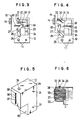
- two guide shafts 11 (in Figure 2 is shown merely a single shaft) are disposed horizontally in a front region of a housing case 10.
- a carrier 12 is mounted on the guide shafts 11 in a manner to be reciprocable leftward and rightward, and a printer head 13 is supported in the carrier 12.
- an opposed electrode 14 is positioned horizontally to confront the printer head 13.
- Tractors 16 are disposed behind the opposed electrode 14 for feeding a recording paper 15 which is guided between the opposed electrode 14 and the printer head 13.
- an operating knob 17 projecting outward is connected to the tractors 16.
- the carrier 12 is equipped with a guide support shaft 18 projecting toward the opposed electrode 14, and the printer head 13 is attached reciproc- ably to the guide support shaft 18.
- a tension spring 19 is interposed between the printer head 13 and the carrier 12 so as to pull the printer head 13 away from the opposed electrode 14.
- a cap 20 is attached to the top end of the carrier 12 in a manner to be rotatable around a pin 21 and is elastically urged by the tension spring 22 to cover the front of the printer head 13.
- a solenoid 23 is disposed under the carrier 12.
- the solenoid 23 is equipped with a moving core 24 engaged, at its end, with a slide slot 27 which is formed at an intermediate position of a ⁇ -shaped lever 26 held rotatably at a lower end thereof by a pivot 25.
- the lever 26 has another slide slot 28 at its upper end, and the printer 13 is linked with the slot 28.
- a slide hole 30 for permitting insertion of the guide support shaft 18 is formed in a lower portion of a box-shaped head case 29, and hooks 31 for anchoring the tension springs 19 and 22 are disposed on one side of the head case 29.
- An ink tank 33 for containing ink 32 is formed in an upper portion of the head case 29, and an ink supply port 34 is formed in the top of the head case 29 for enabling the ink tank 33 to communicate with the outside.
- the ink supply port 34 is covered with a lid 35.
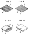
- a plate-shaped ink supply member 37 is disposed with a plurality of recording electrodes 36 arrayed fixedly thereon at equal intervals.
- the fore end of the ink supply member 37 is fitted into an electrode slit 38 formed through the front of the ink tank 33 and is thereby exposed to the outside.
- Each of the recording electrodes 36 consists of a plate-shaped conductive element, and the ink supply member 37 is composed of a material having both insulation property and ink-impregnation property. More specifically, the recording electrode 36 is composed of copper, titanium or nickel.
- the ink supply member 37 is composed of polyester fibers which have a porosity of 30 to 60% with a pore diameter of 20 to 40 microns and are bundled and bonded firmly with a binder in such a manner as to retain air permeability. In the structure of such polyester fibers, the pores are coupled to one another three- dimensionally.
- the ink 32 used in this example has properties including a viscosity of 3 to 7 cp, a surface tension of 19 to 21 dyne/cm and a resistivity of (1-6) x 10 7 ohm-cm
- the rear ends of the recording electrodes 36 are connected via connectors C to individual ends of high-voltage switches 39 respectively, whose other ends are connected to the opposed electrode 14 via two divided high-voltage power sources 40 and 41.
- the mid-point of connection of such high-voltage power sources 40 and 41 is grounded.
- a printing control circuit 42 which generates a control signal corresponding to a picture signal.
- the solenoid 23 is energized prior to starting a printing operation. Then the movable core 24 is actuated to move forward, thereby displacing the printer head 13 to the proximity of the opposed electrode 14. At this moment the cap 20 is pushed and turned by the printer head 13, whose fore end is thereby opened to be ready for printing. With-regard to such positional change of the printer head 13, Fig. 3 shows an initial position and Fig. 4 a printing ready position. Meanwhile, upon completion of the printing operation, first the solenoid 23 is deenergized. Then the printer head 13 is returned to its former position by the tension spring 19, and the cap 20 is pulled backward bythetension spring 22to coverthefore end of the printer head 13. Thus the ink32 can be kept undried with certainty during non-use of the printer.
- the ink 32 Since the ink supply member 37 is mostly impregnated with the ink 32 contained in the tank 33, the ink 32 is absorbed to spread throughout the ink supply member 37. Accordingly the ink 32 is fed via the ink supply member 37 to the fore ends of the recording electrodes 36. In this stage the ink 32 is fed to the fore ends of the recording electrodes 36 is held in the ink supply member 37, so that it is prevented from dripping. Therefore an adequate amount of the ink 32 can be fed to the fore end of each recording electrode 36. When a print signal is applied in a state where the printer head 13 is set at its printing ready position, the ink 32 at the fore end of the recording electrode 32 is sputtered in a sufficient amount.
- the printing signal is applied selectively from the printing control circuit 42 to the high-voltage switch 39. Then a potential difference is generated between the energized recording electrode 36 and the opposed electrode 14 by the high-voltage power sources 40 and 41, so that the ink 32 at the fore end of the recording electrode 36 is subjected to an electrostatic force and is thereby sputtered toward the opposed electrode 14.
- the ink 32 thus sputtered is in the shape of small droplets to form a dot when deposited on the recording paper 15. A multiplicity of such dots are aggregated selectively to print a character or figure on the recording paper 15.
- the printer head 13 and the recording paper 15 are moved relatively to each other during a printing operation, the fore end of the printer head 13 or the ink supply member 37 projecting from the electrode slit 38 may come into contact with the recording paper 15. Even in such a case, however, the ink 32 in the relevant portion of contact is held within the ink supply member 37 and never causes conspicuous soil on the recording paper 15. Consequently it becomes possible to prevent a trouble of soiling the recording paper 15 much to eventually ensure a satisfactory printing operation.
- Feeding the ink 32 to the fore ends of the recording electrodes 36 can be executed merely by immersing the ink supply member 37 in the ink 32, and no particular mechanism is required at all. Accordinglythe printer head 13 can be produced in a remarkably simple structure to eventually realize a low-cost apparatus of high reliability with elimination of mechanical wear and fatigue.
- the ink 32 is substantially kept away from touch with air as it is held within the ink supply member 37, whereby the ink 32 fed to the fore ends of the recording electrodes 36 is effectively prevented from drying in combination with another merit that the printer head 13 is covered with the cap 20 during non-use of the printer.
- Figs. 8 through 10 show some exemplary modifications of recording electrodes 36 and an ink supply member 37.
- grooves 43 for fitting flat plate-shaped recording electrodes 36 therein are formed in the ink supply member 37, and the individual recording electrodes 36 are fitted and anchored respectively in the grooves 43.
- the surface of the ink supply member 37 supporting the recording electrodes 36 is shaped into a smooth plane to permit complete contact between the ink supply member 37 and the electrode slit 38 in the printer head 13.
- needle- shaped recording electrodes 36 are anchored in connection with a plurality of leads 44 formed on a thin-film PC board 45, and the recording electrodes 36 are sandwiched between two ink supply members 37.
- the recording electrodes 36 may be inserted into a single ink supply member 37 as well.
- recording electrodes 36 are interposed between two ink supply members 37 which are covered with a holding case 46, wherein merelythe fore ends of the recording electrodes 36 and the peripheries thereof are exposed to the outside. It becomes possible in this modification to increase the amount of the ink 32 fed to the fore ends of the recording electrodes 36.
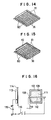
- recording electrodes 36 are formed on an ink supply member 37 by thin film technique. Accordingly a higher degree offreedom is achievable with respect to the shape of the recording electrodes 36 and also in designing the connector C or connection between high-voltage switches 39 and the recording electrodes 36. And pores in the ink supply member 37 are never crushed at the time of forming the recording electrodes 36 because the film thickness of each recording electrode 36 can be reduced to less than 0.5 microns.
- the ink 32 is permitted to flow smoothly to the individual pores and is thereby fed effectively to the fore end of each recording electrode 36.
- the film thickness of the recording electrode 36 is less than 0.5 microns, it is sufficient for practical use since substantially no current flows in the recording electrodes 36 to eventually bring about no disadvantage such as generation of heat.
- recording electrodes 36 are formed on an insulator plate 50, and an ink supply member 37 is disposed in contact with the recording electrodes 36.
- an ink supply member 37 is retained merely in contact with the recording electrodes 36, pores in the ink supply member 37 are not deformed at all to consequently ensure effective feed of the ink 32 to the fore ends of the recording electrodes 36.
- Each of the electrodes 36 may be either shaped into a plate or formed by thin film technique.
- FIG. 13 through 15 shows exemplary modifications.
- Figs. 14 and 15 show exemplary modifications. First in the example of Fig.
- a plurality of penpoint-like ink supply members 61 are coupled to one another, and recording electrodes 36 are formed on such ink supply members 61 by thin film technique, whereby the tapered tip of each ink supply member 61 is shaped into a projection 60.
- the ink supply members 61 may be bonded or welded to one another after forming the recording electrodes 36, and such steps may be carried out in the reverse order as well.
- the process of forming the recording electrodes 36 either etching or masking may be adopted.
- Fig. 15 its structure is the same as the example shown in Fig. 14 with the exception that ink supply members 61 are anchored firmly on a base 62.
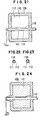
- a printer head 107 comprises a case 109 having an opening 108 in its front portion, an ink supply member 111 impregnated with ink 110 contained in the case 109, and a conductive recording electrode 112 extending therethrough to project from the opening 108.
- the fore end of the recording electrode 112 is shaped to be arcuate and projects from the surface of the case 109 by a dimension h o which corresponds to a wetting height of the ink 110.
- the wetting height h o means the rise of the ink 110 induced due to the hydrophilic property of the electrode surface when the recording electrode 112 is in contact with the surface of the ink 110 as shown in Fig. 17.
- a plate-shaped opposed electrode 113 is positioned opposite to the printer head 107, and a recording paper 114 is joined to one surface of the opposed electrode 113 confronting the printer head 107. And between the opposed electrode 113 and the recording electrode 112, there are connected a power source 115 for causing a potential difference sufficient to sputter the ink 110, and also a switch 116 serving as a print signal circuit to generate such potential difference in accordance with a print signal.
- a power source 115 for causing a potential difference sufficient to sputter the ink 110
- a switch 116 serving as a print signal circuit to generate such potential difference in accordance with a print signal.
- three points a, b and c are set as shown in Fig. 16 for the convenience of explanation. And suppose now that point a corresponding to the opposed electrode 113 is grounded.
- the ink 110 having reached the fore end of the recording electrode 112 rises to the wetting height h o .
- the switch 116 is turned on or off in accordance with a print signal received in such a state.
- a high voltage is applied between the opposed electrode 113 and the recording electrode 112 to sputter the ink 110 from the fore end of the recording electrode 112 toward the opposed electrode 113.
- the printer head 107 is reciprocated horizontally while the recording paper 114 is displaced vertically with on-off control of the switch 116, so that the dots formed with the ink 110 are positionally changed, and a character or figure is drawn with an aggregation of such dots.
- the recording electrode 112 projects from the ink supply member 111, it functions similarly to an ordinary pen even when the recording paper 114 comes into contact with the printer head 107, hence avoiding a trouble of inducing conspicious soil of the recording paper 114.
- the distance between the recording paper 114 and the recording electrode 112 can be increased to reduce the probability of causing contact of the recording paper 114 with the recording electrode 112, whereby enhancing facility is attainable in handling the printer.
- the fore end of the recording electrode 112 is shaped to be arcuate in the above embodiment, it may be conical or pyramidal as well.
- Fig. 19 shows a sixth embodiment of the present invention, wherein components identical or corresponding to those used in the fifth embodiment are denoted by like reference numerals, and a repeated explanation is omitted here. (This applies also to the next and following embodiments.)
- an ink chamber 117 is formed in a case 109 so as to increase the holdable amount of ink 110 therein for prolonging the continuous printing time.
- Fig. 20 shows a seventh embodiment of the present invention, wherein an ink supply member 111 partially projects from an opening 108 so that ink 110 can be fed to the fore end of a recording electrode 112 further smoothly.
- a recording electrode 112 is composed of an ink-impregnable element 111 and a conductive element 118.
- the conductive element 118 partially constitutes the recording electrode 112 in a cross-sectional view and, at the fore end thereof, the ink-impregnable element 111 projects beyond the conductive element 118 by a dimension h, which is 0.1 mm or so. Therefore the ink 110 can be fed thoroughly to the fore end of the recording electrode 112, and satisfactory refillability is achievable to maintain sufficient supply of the ink 110 even in a fast printing operation.
- a ninth embodiment of the present invention will be described below with reference to Fig. 24, wherein a case 109 is filled with an ink supply member 111 which projects from an opening 108 in a manner to form a protuberance, and the fore end of a recording electrode 112 is inserted into such protruberance without being exposed to the outside. And a portion of the ink supply member 111 positioned at the fore end of the recording electrode 112 is so shaped as to have a thickness h i .
- an opening 108 is formed into an elongate slit, and a plurality of recording electrodes 112 are disposed longitudinally along the opening 108 with insulator walls 119 interposed between the recording electrodes 112.
- Such arrangement is effective for preventing generation of arcs between the recording electrodes 112, and printing can be performed with application of high-voltage pulses individually thereto. Consequently it becomes possible to increase the number of recording electrodes 112 to execute a fast printing operation.
- an eleventh embodiment of the present invention will now be described with reference to Fig. 26, wherein an ink supply member 111 is similar in shape to the aforementioned ninth embodiment, and protuberances are arrayed serially in an elongate slit similar to the opening 108 in the tenth embodiment.
- point a is grounded so as to prevent arching between the opposed electrode 113 and the recording electrode 112. Electrons are readily emitted if the dot-like recording electrodes 112 are poled negative. However, arcing hardly occurs in the arrangement where the opposed electrode 113 is poled negative as in the embodiments. Furthermore, complete safety can be maintained despite exposure of the opposed electrode 113.
- point c may be grounded as well in implementing the invention. Although there exists a disadvantage that arcing is prone to occur in such a case, the potential of the printer head 107 is rendered lower to eventually facilitate manufacture of the apparatus.
Landscapes
- Physics & Mathematics (AREA)
- General Physics & Mathematics (AREA)
- Particle Formation And Scattering Control In Inkjet Printers (AREA)
Claims (12)
Applications Claiming Priority (4)
| Application Number | Priority Date | Filing Date | Title |
|---|---|---|---|
| JP56582/85 | 1985-03-20 | ||
| JP60056582A JPH0645240B2 (ja) | 1985-03-20 | 1985-03-20 | インクドツトプリンタ |
| JP60204846A JPS6264556A (ja) | 1985-09-17 | 1985-09-17 | 印刷装置 |
| JP204846/85 | 1985-09-17 |
Publications (2)
| Publication Number | Publication Date |
|---|---|
| EP0196820A1 EP0196820A1 (fr) | 1986-10-08 |
| EP0196820B1 true EP0196820B1 (fr) | 1988-11-23 |
Family
ID=26397536
Family Applications (1)
| Application Number | Title | Priority Date | Filing Date |
|---|---|---|---|
| EP86301982A Expired EP0196820B1 (fr) | 1985-03-20 | 1986-03-18 | Imprimante à points d'encre |
Country Status (4)
| Country | Link |
|---|---|
| US (2) | US4806956A (fr) |
| EP (1) | EP0196820B1 (fr) |
| KR (1) | KR910004026B1 (fr) |
| DE (1) | DE3661245D1 (fr) |
Families Citing this family (23)
| Publication number | Priority date | Publication date | Assignee | Title |
|---|---|---|---|---|
| KR910004026B1 (ko) * | 1985-03-20 | 1991-06-22 | 도오꾜오덴끼 가부시끼가이샤 | 잉크 도트 프린터 |
| JPS62225358A (ja) * | 1986-03-27 | 1987-10-03 | Fuji Xerox Co Ltd | 画像記録ヘツド |
| JPS6399952A (ja) * | 1986-10-16 | 1988-05-02 | Tokyo Electric Co Ltd | インクジエツトプリンタ及びその印刷方法 |
| USD314210S (en) | 1988-09-02 | 1991-01-29 | Seikosha Co., Ltd. | Printing head for a printer of a computer |
| USD314007S (en) | 1988-09-02 | 1991-01-22 | Seikosha Co., Ltd. | Printing head for a printer of a computer |
| USD325743S (en) | 1989-04-13 | 1992-04-28 | Canon Kabushiki Kaisha | Printing head for printer |
| US5323847A (en) * | 1990-08-01 | 1994-06-28 | Hitachi, Ltd. | Electronic apparatus and method of cooling the same |
| US5477249A (en) * | 1991-10-17 | 1995-12-19 | Minolta Camera Kabushiki Kaisha | Apparatus and method for forming images by jetting recording liquid onto an image carrier by applying both vibrational energy and electrostatic energy |
| JP2906889B2 (ja) * | 1992-12-01 | 1999-06-21 | 富士ゼロックス株式会社 | 画像記録用ヘッド |
| JP2907085B2 (ja) * | 1995-12-14 | 1999-06-21 | 日本電気株式会社 | インクジェット式ヘッド装置 |
| JP2783230B2 (ja) * | 1995-12-18 | 1998-08-06 | 日本電気株式会社 | 静電式インクジェット記録ヘッド |
| GB9601212D0 (en) * | 1996-01-22 | 1996-03-20 | The Technology Partnership Plc | Inkjet printer nozzle plate |
| DE69720862T2 (de) * | 1996-06-17 | 2003-10-16 | Nec Corp., Tokio/Tokyo | Tintenstrahlaufzeichnungsapparat |
| JP3215629B2 (ja) | 1996-07-12 | 2001-10-09 | シャープ株式会社 | 記録ヘッド |
| US6068370A (en) * | 1996-08-30 | 2000-05-30 | Hewlett-Packard Company | Fluidic delivery system with tubing and manifolding for an off-axis printing system |
| US5988801A (en) * | 1996-09-30 | 1999-11-23 | Hewlett-Packard Company | High performance tubing for inkjet printing systems with off-board ink supply |
| US6095638A (en) * | 1996-11-21 | 2000-08-01 | Nec Corporation | Elastic ink jet printing head and method for manufacturing head block thereof |
| US6547616B1 (en) * | 1998-04-15 | 2003-04-15 | Fujitsu Display Technologies Corporation | Display, its manufacture, ink coating apparatus, all suitable for narrowing display frame |
| US6995024B2 (en) * | 2001-08-27 | 2006-02-07 | Sri International | Method and apparatus for electrostatic dispensing of microdroplets |
| JP2004106300A (ja) * | 2002-09-17 | 2004-04-08 | Sharp Corp | インクカートリッジ及び画像形成装置 |
| US8894181B2 (en) * | 2010-01-04 | 2014-11-25 | King Saud University | Printing system and method |
| KR101843145B1 (ko) * | 2017-02-20 | 2018-03-28 | 서울대학교산학협력단 | 의료용 석션 팁 |
| KR101940563B1 (ko) * | 2017-05-12 | 2019-01-22 | 주식회사 로보프린트 | 이미지 가공 방법, 이미지 자동 인쇄 방법 및 자동인쇄장치용 노즐 |
Family Cites Families (12)
| Publication number | Priority date | Publication date | Assignee | Title |
|---|---|---|---|---|
| US3666966A (en) * | 1970-07-21 | 1972-05-30 | Wolfgang Joseph Buss | Electronic switch |
| JPS5845352B2 (ja) * | 1977-06-13 | 1983-10-08 | 株式会社リコー | 記録方法 |
| JPS56170A (en) * | 1979-06-15 | 1981-01-06 | Nippon Telegr & Teleph Corp <Ntt> | Ink recording system |
| US4271416A (en) * | 1978-10-18 | 1981-06-02 | Nippon Telegraph And Telephone Public Corporation | Slit type ink recording apparatus |
| JPS6059869B2 (ja) * | 1979-06-22 | 1985-12-27 | 日本電信電話株式会社 | インク記録用ヘツド |
| JPS6051986B2 (ja) * | 1979-09-14 | 1985-11-16 | 大阪機工株式会社 | 適応制御倣い工作機械 |
| JPS5849190B2 (ja) * | 1979-09-17 | 1983-11-02 | 日本電信電話株式会社 | インク記録用ヘツド |
| JPS5738163A (en) * | 1980-08-18 | 1982-03-02 | Matsushita Electric Ind Co Ltd | Image recording method and apparatus therefor |
| JPS59229345A (ja) * | 1983-05-24 | 1984-12-22 | Fuji Xerox Co Ltd | 画像記録装置 |
| JPS6090771A (ja) * | 1983-10-26 | 1985-05-21 | Tokyo Electric Co Ltd | インクドツトプリンタ− |
| KR910004026B1 (ko) * | 1985-03-20 | 1991-06-22 | 도오꾜오덴끼 가부시끼가이샤 | 잉크 도트 프린터 |
| JPS61215060A (ja) * | 1985-03-22 | 1986-09-24 | Tokyo Electric Co Ltd | 印刷装置 |
-
1986
- 1986-03-14 KR KR1019860001866A patent/KR910004026B1/ko not_active Expired
- 1986-03-18 DE DE8686301982T patent/DE3661245D1/de not_active Expired
- 1986-03-18 EP EP86301982A patent/EP0196820B1/fr not_active Expired
-
1988
- 1988-04-08 US US07/180,689 patent/US4806956A/en not_active Expired - Fee Related
- 1988-12-01 US US07/278,448 patent/US4905024A/en not_active Expired - Fee Related
Also Published As
| Publication number | Publication date |
|---|---|
| EP0196820A1 (fr) | 1986-10-08 |
| US4905024A (en) | 1990-02-27 |
| DE3661245D1 (en) | 1988-12-29 |
| KR860007094A (ko) | 1986-10-08 |
| KR910004026B1 (ko) | 1991-06-22 |
| US4806956A (en) | 1989-02-21 |
Similar Documents
| Publication | Publication Date | Title |
|---|---|---|
| EP0196820B1 (fr) | Imprimante à points d'encre | |
| JPH0437787B2 (fr) | ||
| US4315267A (en) | Method of magnetofluidic recording | |
| GB2089735A (en) | Apparatus for deflecting ink drops | |
| US6244690B1 (en) | Apparatus for jetting ink using a magnet and a plurality of coils installed on a plate to generate a magnetic field | |
| US4801952A (en) | Improved ink dot printer electrode structure | |
| JPS58502191A (ja) | 静電式インク・ジエット装置 | |
| US4868585A (en) | Ink dot printer | |
| EP0257985B1 (fr) | Electrode d'enregistrement conductrice pour dispositifs d'impression | |
| US4696589A (en) | Ink-dot printer | |
| US4188133A (en) | Dot matrix impact printer employing magnetic dot elements | |
| JP2783227B2 (ja) | 静電式インクジェット記録装置 | |
| KR910004027B1 (ko) | 잉크 도트 프린터 | |
| EP0067953B1 (fr) | Dispositif d'impression électrothermique | |
| JPS6362747A (ja) | 高画質サ−マルプリンタ | |
| JPH051145B2 (fr) | ||
| JPS6264556A (ja) | 印刷装置 | |
| JPS61219660A (ja) | サ−マルインクジエツト記録装置 | |
| JPH08258281A (ja) | インク吐出装置 | |
| JPS623241Y2 (fr) | ||
| JPH0462541B2 (fr) | ||
| JPH0645240B2 (ja) | インクドツトプリンタ | |
| JPH0544346B2 (fr) | ||
| JPS61233547A (ja) | 印刷装置 | |
| JPH0952366A (ja) | 静電式インクジェット記録ヘッド |
Legal Events
| Date | Code | Title | Description |
|---|---|---|---|
| PUAI | Public reference made under article 153(3) epc to a published international application that has entered the european phase |
Free format text: ORIGINAL CODE: 0009012 |
|
| AK | Designated contracting states |
Kind code of ref document: A1 Designated state(s): DE FR GB |
|
| 17P | Request for examination filed |
Effective date: 19861003 |
|
| 17Q | First examination report despatched |
Effective date: 19880212 |
|
| GRAA | (expected) grant |
Free format text: ORIGINAL CODE: 0009210 |
|
| AK | Designated contracting states |
Kind code of ref document: B1 Designated state(s): DE FR GB |
|
| REF | Corresponds to: |
Ref document number: 3661245 Country of ref document: DE Date of ref document: 19881229 |
|
| ET | Fr: translation filed | ||
| PLBE | No opposition filed within time limit |
Free format text: ORIGINAL CODE: 0009261 |
|
| STAA | Information on the status of an ep patent application or granted ep patent |
Free format text: STATUS: NO OPPOSITION FILED WITHIN TIME LIMIT |
|
| 26N | No opposition filed | ||
| PGFP | Annual fee paid to national office [announced via postgrant information from national office to epo] |
Ref country code: FR Payment date: 19930225 Year of fee payment: 8 |
|
| PGFP | Annual fee paid to national office [announced via postgrant information from national office to epo] |
Ref country code: GB Payment date: 19930304 Year of fee payment: 8 |
|
| PGFP | Annual fee paid to national office [announced via postgrant information from national office to epo] |
Ref country code: DE Payment date: 19930430 Year of fee payment: 8 |
|
| PG25 | Lapsed in a contracting state [announced via postgrant information from national office to epo] |
Ref country code: GB Effective date: 19940318 |
|
| GBPC | Gb: european patent ceased through non-payment of renewal fee |
Effective date: 19940318 |
|
| PG25 | Lapsed in a contracting state [announced via postgrant information from national office to epo] |
Ref country code: FR Effective date: 19941130 |
|
| PG25 | Lapsed in a contracting state [announced via postgrant information from national office to epo] |
Ref country code: DE Effective date: 19941201 |
|
| REG | Reference to a national code |
Ref country code: FR Ref legal event code: ST |