EP0197542A2 - Selektive Rufvorrichtung mit Anzeiger - Google Patents
Selektive Rufvorrichtung mit Anzeiger Download PDFInfo
- Publication number
- EP0197542A2 EP0197542A2 EP86104777A EP86104777A EP0197542A2 EP 0197542 A2 EP0197542 A2 EP 0197542A2 EP 86104777 A EP86104777 A EP 86104777A EP 86104777 A EP86104777 A EP 86104777A EP 0197542 A2 EP0197542 A2 EP 0197542A2
- Authority
- EP
- European Patent Office
- Prior art keywords
- display
- signal
- error
- message
- selective call
- Prior art date
- Legal status (The legal status is an assumption and is not a legal conclusion. Google has not performed a legal analysis and makes no representation as to the accuracy of the status listed.)
- Withdrawn
Links
Images




Classifications
-
- G—PHYSICS
- G08—SIGNALLING
- G08B—SIGNALLING SYSTEMS, e.g. PERSONAL CALLING SYSTEMS; ORDER TELEGRAPHS; ALARM SYSTEMS
- G08B5/00—Visible signalling systems, e.g. visible personal calling systems or remote indication of seats occupied
- G08B5/22—Visible signalling systems, e.g. visible personal calling systems or remote indication of seats occupied using electric transmission; using electromagnetic transmission
- G08B5/222—Personal calling arrangements or devices, i.e. paging systems
- G08B5/223—Personal calling arrangements or devices, i.e. paging systems using wireless transmission
- G08B5/224—Paging receivers with visible signalling details
- G08B5/225—Display details
-
- G—PHYSICS
- G08—SIGNALLING
- G08B—SIGNALLING SYSTEMS, e.g. PERSONAL CALLING SYSTEMS; ORDER TELEGRAPHS; ALARM SYSTEMS
- G08B5/00—Visible signalling systems, e.g. visible personal calling systems or remote indication of seats occupied
- G08B5/22—Visible signalling systems, e.g. visible personal calling systems or remote indication of seats occupied using electric transmission; using electromagnetic transmission
- G08B5/222—Personal calling arrangements or devices, i.e. paging systems
- G08B5/223—Personal calling arrangements or devices, i.e. paging systems using wireless transmission
- G08B5/224—Paging receivers with visible signalling details
- G08B5/229—Paging receivers with visible signalling details with other provisions not elsewhere provided for
Definitions
- This invention relates to a selective call receiving apparatus or paging receiver having a display- which receives a paging signal including a selective calling signal or address signal and a message signal sent from a radio transmitter.
- the selective call receiving apparatus having a di-splay is generally constituted by a receiving section, a signal processing section, a display section, an error processing section, and an alert signal generating section.
- the signal processing section contains a number setting circuit which presets its own call number.
- a carrier wave modulated with a selective calling signal and a message signal is transmitted from the transmitter.
- the transmitted wave is received by the receiving section and its waveform is then shaped.
- the signal processing section compares a received selective calling signal with a call number preset in the number setting circuit.
- a loudspeaker provided for the alert signal generating section generates an alert for informing to one who carries with the receiver that there is a call and for displaying the received message on the display of the display section.
- the message signal is sent to the error processing section which detect that the message signal contains an error, and it produces an error detection signal which drives the display section so as to cause it to display the error.
- an area for displaying a message and an area for displaying the error of the message are provided for the display surface of the display so that, when an error is detected in the message, a special symbol such as dot, cursor or the like is displayed on the error display area, in addition to the message to be displayed on the message display area.
- Fig. lA shows a case when there is now error
- Figs. 1B and lC show examples of displaying an error with dot and a cursor, respectively.
- the prior art selective call receiving apparatus having display has the following defects. First, it is necessary to provide a circuit for displaying a special error symbol on the error display area and hence the processing of the display signal is complicated. Second, since the error display area is used only for displaying the error, the efficient utilization of the display area is precluded. Third, identification of erroneous message is not always easy.
- a selective call receiving apparatus having display comprising receiving means for receiving a signal representing a selective call number and a signal representing a message; a signal processing means including means for presetting a selective call number of the selective call receiving apparatus and comparing the received selective call number with the preset selective call number to output an alert signal and a message signal when the compared signals coincide with each other; an error detecting means supplied with the message signal for producing an error signal when there is an error in the message signal; display means including a display supplied with the message signal and the output signal of the error detecting means for converting message signals containing and not containing the error into opposite signals, thereby displaying the message signals containing and not containing the error with opposite contrasts on the display.
- the output terminal of a receiving section 2 including an antenna 1 for receiving signals is connected to the input terminal of a waveform shaper 3.
- the output terminal of the waveform shaper 3 is connected to the input terminal of a signal processing circuit 4 which is also supplied with the output of a call number setting circuit 5.
- the receiving section 2 and the waveform shaper 3 operate intermittently or continuously in accordance with control signals supplied from the processing circuit 4 through respective control lines, not shown.
- the output terminal 4a of the signal processing circuit 4 is connected to the input terminal of an alert signal generator 6 with an output terminal connected to a loudspeaker 7.
- the other output terminal 4b of the signal processing circuit 4 is connected to the input terminals of a display controller 8 and an error detector 9.
- the output terminals of the display controller 8 and of the error detector 9 are respectively connected to the input terminals 10a and 10b of a display data processor 10.
- the output terminal of the display,data processor 10 is connected to the input of a display driver 11 with an output terminal connected to a display 12.
- a carrier wave modulated with a selective calling signal and with a message signal which is sent from a transmitter, not shown, is received by antenna 1 and both of the selective calling signal and the message signal are demodulated by the receiving section 2 and unwanted noise components are eliminated by a low pass filter, not shown, of the waveform shaper 3, and the waveforms of the demodulated signals are shaped into rectangular waves by a comparator, not shown, the rectangular waves being sent to the signal processor 4.
- Fig. 3A shows the construction of the received signal in which N designates a selective call number word comprising 32 bits,'and I 1 , I 2 , I3 ... designate message words each comprising 32 bits.
- P represents a preamble signal and F a frame synchronizing signal.
- Figs. 3B and 3C respectively show bit configurations of the selective call number word and the message word.
- the first bit D of each word is a designator for identifying that whether the word is the selective call number word or the message word. In the case of the selective call number word, it is shown by a logic "0" whereas in the case of the message word it is shown by a logic "1". 20 bits from the second to the 21th bits contain a selective call number or a message.
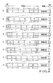
- Succeeding 10 bits are check bits for any word and the last one bit is an even parity bit EP. Since the display device displays one character with 7 bits code, the bit positions of the character codes in respective message words I 1 , I 2 ... vary as shown in Fig. 4 which shows a case when alphabets A-W are sequentially received as the message. As can be noted. from Fig. 4, the bit positions in one wo.rd are repeated with 7 words as one period.
- the signals shown by Figs. 3A, 3B and 3C and inputted to the signal processing circuit 4 are processed as shown in the flow chart of Fig. 5.
- the receiver 2 and the waveform shaper 3 are operating intermittently, and a judgment is made as to whether a signal received is a .. preamble signal P or not.
- the preamble signal P is detected, the reception of the signal is continued, and the flow is advanced to step S52.
- the step S51 repeated.
- step S52 signal reception is made for a definite interval during which a judgment is made as to whether a frame synchronizing signal F has been received or not.
- the flow is advanced to step S53. If signal F is not detected the flow is returned to step S51 for executing the intermittent operation.
- step S53 the input words are synchronized with the output of the call number setting circuit 5 using the detected frame synchronizing signal F, and the content of the received selective call number word is compared with the number preset in the number setting circuit 5 in order to detect the message addressing to own selective call receiving apparatus. If a result of the comparison indicates that the both numbers are coincident with each other, the flow is advanced to step S54, but when the coincidence is not detected, the flow is returned to step S51.
- step S54 the alert generating circuit 6 is driven to generate an alert and the display circuit 8 and the error detector 9 are started.
- step S55 the message signal sent after the selective call number signal is processed for sending message data to the display control circuit 8 and the error detector 9.
- step S56 the flow is advanced to step S56 for checking whether or not the message is completed. This may be done by checking message end bits contained in the message signal. When the message end bits are not detected, the flow is returned to step S55 for continueing the message data reception, whereas when the message end bits are detected, the flow is returned to step S51 after the signal terminates and the intermittent operation is performed.
- Fig. 6 is a flow chart for describing the operation of the display controller 8 shown in Fig. 2.
- the flow is advanced to step S61 at which a message buffer memory, not shown, for storing 32 bits data is cleared.
- step S62 the 32 bits data received from the signal processor 4 is stored in the-message buffer memory.
- step S63 the most significant bit (MSB) of the stored data is checked for judging whether the data corresponds to a message or not. In other words, when the MSB is "1", the signal is judged as the message signal and the flow is advanced to step S64, whereas when the signal is not the message signal, the flow is transferred to step S65.
- MSB most significant bit
- step S64 the character data each including 7 bits are derived out from the information bits (20 bits) and the derived out character codes are supplied to the display data processor 10. If the extracted character code data does not include 7 bits, the data is temporarily stored in a dummy buffer memory for waiting the reception of the next word.
- step S65 a termination signal of the message data is sent to the signal processor 4, thus terminating the operation.
- Fig. 7 is a flow chart for describing the operation of the error detector 9.
- the flow enters into step S71 at which the 32 bits data is received from the signal processor 4 and a syndrome is calculated.
- step S72 a judgment is made as to whether the value of the syndrome is zero or not for judging whether there is an error or not. Thus, where there is an error, it is judged by utilizing the fact that the value of its syndrom does not become zero.
- the error detection signal is made operative or inoperative according to the value of the syndrome.
- Fig. 8 is a flow chart for describing the operation of the display data processor 10.
- a character generator not shown, in the display data processor 10 converts the 7 bits character code signal supplied from the display controller 8 into a 5x7 or 5x8 bits code and supplies the converted code to the display driver 11 as a display data.
- a judgment is made as to whether there is an error detection signal from the error detector 9.
- the flow is branched to steps S82 and S83 in accordance with the result of the judgment.
- Step S83 shows a processing when an error is not detected, and the display data is stored in a display random access memory (RAM), not shown, in the display driver 11 as it is.
- Step S82 shows a processing when an error is detected.
- the logic of the display data is inverted and then stored in the display RAM.
- the display driver 11 generates signals for driving LCD display elements.
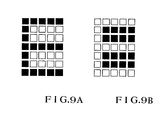
- Figs. 9A and 9B show examples of the displayed character according to the present invention.
- Fig. 9A shows a display of a letter E under a normal condition that is with no error.
- Fig. 9B shows a reverse display of the letter E which is judged as an erroneous letter. More particularly, the display 12 displays one letter or character with 5x7 dots. In the normal condition the dots representing the letter are bright (black portions in Fig. 9A) and other dots are dark (white portions in Fig. 9A). In Figs. 9A and 9B, bright and dark portions are shown opposite. With this mode of display, whether there is an error or not can be readily judged so that it is not necessary to provide dots or cursor at the lower portion.
- the selective call receiving apparatus embodying the invention not only the display area of the display device can be efficiently utilized but also the construction of the display circuit can be simplified. Moreover, the error character can readily be identified.
Landscapes
- Physics & Mathematics (AREA)
- Engineering & Computer Science (AREA)
- Computer Networks & Wireless Communication (AREA)
- Electromagnetism (AREA)
- General Physics & Mathematics (AREA)
- Mobile Radio Communication Systems (AREA)
Applications Claiming Priority (2)
| Application Number | Priority Date | Filing Date | Title |
|---|---|---|---|
| JP60073533A JPS61232732A (ja) | 1985-04-09 | 1985-04-09 | 表示機能付選択呼出受信装置 |
| JP73533/85 | 1985-04-09 |
Publications (2)
| Publication Number | Publication Date |
|---|---|
| EP0197542A2 true EP0197542A2 (de) | 1986-10-15 |
| EP0197542A3 EP0197542A3 (de) | 1988-09-14 |
Family
ID=13520961
Family Applications (1)
| Application Number | Title | Priority Date | Filing Date |
|---|---|---|---|
| EP86104777A Withdrawn EP0197542A3 (de) | 1985-04-09 | 1986-04-08 | Selektive Rufvorrichtung mit Anzeiger |
Country Status (6)
| Country | Link |
|---|---|
| EP (1) | EP0197542A3 (de) |
| JP (1) | JPS61232732A (de) |
| KR (1) | KR900005236B1 (de) |
| CN (1) | CN86102554B (de) |
| AU (1) | AU588866B2 (de) |
| CA (1) | CA1271225A (de) |
Cited By (1)
| Publication number | Priority date | Publication date | Assignee | Title |
|---|---|---|---|---|
| US6559753B1 (en) * | 1998-08-19 | 2003-05-06 | Nec Corporation | Selective radio call receiver capable of receiving common data in emergency mode |
Families Citing this family (1)
| Publication number | Priority date | Publication date | Assignee | Title |
|---|---|---|---|---|
| JPH03267825A (ja) * | 1990-03-16 | 1991-11-28 | Nec Corp | 表示機能付き無線選択呼出受信機 |
Family Cites Families (2)
| Publication number | Priority date | Publication date | Assignee | Title |
|---|---|---|---|---|
| GB2117958B (en) * | 1982-03-29 | 1985-06-12 | Smiths Industries Plc | Matrix display with switched format |
| GB2136248A (en) * | 1983-02-25 | 1984-09-12 | Philips Electronic Associated | Text error correction in digital data transmission systems |
-
1985
- 1985-04-09 JP JP60073533A patent/JPS61232732A/ja active Pending
-
1986
- 1986-04-08 CA CA000506043A patent/CA1271225A/en not_active Expired - Lifetime
- 1986-04-08 AU AU55743/86A patent/AU588866B2/en not_active Ceased
- 1986-04-08 KR KR1019860002632A patent/KR900005236B1/ko not_active Expired
- 1986-04-08 EP EP86104777A patent/EP0197542A3/de not_active Withdrawn
- 1986-04-09 CN CN86102554A patent/CN86102554B/zh not_active Expired
Cited By (1)
| Publication number | Priority date | Publication date | Assignee | Title |
|---|---|---|---|---|
| US6559753B1 (en) * | 1998-08-19 | 2003-05-06 | Nec Corporation | Selective radio call receiver capable of receiving common data in emergency mode |
Also Published As
| Publication number | Publication date |
|---|---|
| KR860008656A (ko) | 1986-11-17 |
| JPS61232732A (ja) | 1986-10-17 |
| CN86102554A (zh) | 1986-10-08 |
| CN86102554B (zh) | 1988-11-30 |
| AU588866B2 (en) | 1989-09-28 |
| CA1271225A (en) | 1990-07-03 |
| AU5574386A (en) | 1986-10-16 |
| EP0197542A3 (de) | 1988-09-14 |
| KR900005236B1 (ko) | 1990-07-21 |
Similar Documents
| Publication | Publication Date | Title |
|---|---|---|
| US5574439A (en) | Paging receiver which displays canned and general messages | |
| AU579698B2 (en) | Method of receiving a radio message of coded characters and storing just once | |
| US6246335B1 (en) | Portable information equipment system and control method thereof | |
| EP0091691A2 (de) | Seitenwechsel-Funkempfänger arbeitend auf Basis einer Wortverschiebung | |
| JPH0767184B2 (ja) | 複数言語使用ページング装置 | |
| US4870403A (en) | Paging receiver with a capability of receiving or inhibiting message data | |
| CN1040057C (zh) | 适用于紧急呼叫的寻呼接收机 | |
| US4554540A (en) | Signal format detection circuit for digital radio paging receiver | |
| EP0232123B1 (de) | Personenruffunkempfänger mit Licht emittierender Diode zur Erzeugung von visuellem Alarm und Signalsendung | |
| EP0197542A2 (de) | Selektive Rufvorrichtung mit Anzeiger | |
| EP0498660A1 (de) | Personenrufempfänger mit Nachrichtenanzeigefunktion | |
| EP0509649B1 (de) | Selektiv-Rufempfänger | |
| JPH03267825A (ja) | 表示機能付き無線選択呼出受信機 | |
| US5801640A (en) | Radio pager with a message processing function | |
| US6292655B1 (en) | Selective calling radio-receiver and method of receiving selective calling radio signal | |
| KR920704247A (ko) | 선택 호출 신호 시스템 | |
| JP2659558B2 (ja) | 選択無線呼出方式 | |
| KR910003233B1 (ko) | 페이징 수신기의 메시지 표시방법 | |
| CA1137585A (en) | Function coding via digital addresses in a two-way system | |
| EP0280405A1 (de) | Nacheinander empfangene Meldungen auswertendes Verfahren und dieses Verfahren benutzender Personenrufempfänger | |
| KR940000705B1 (ko) | 가정 자동화 시스템에서의 비상 자동 전송방법 | |
| CN1241876A (zh) | 选择呼叫接收机及显示接收的消息数据的方法 | |
| US5485146A (en) | Paging receiver | |
| JPS5761360A (en) | Center trouble code transmitter | |
| JPH0226137A (ja) | 無線呼出受信機 |
Legal Events
| Date | Code | Title | Description |
|---|---|---|---|
| PUAI | Public reference made under article 153(3) epc to a published international application that has entered the european phase |
Free format text: ORIGINAL CODE: 0009012 |
|
| 17P | Request for examination filed |
Effective date: 19860416 |
|
| AK | Designated contracting states |
Kind code of ref document: A2 Designated state(s): DE GB NL SE |
|
| RIN1 | Information on inventor provided before grant (corrected) |
Inventor name: YOSHIDA, HIDEO C/O NEC MOBILE RADIO SERVICE LTD. Inventor name: OYAGI, TAKASHI C/O NEC CORPORATION |
|
| PUAL | Search report despatched |
Free format text: ORIGINAL CODE: 0009013 |
|
| AK | Designated contracting states |
Kind code of ref document: A3 Designated state(s): DE GB NL SE |
|
| 17Q | First examination report despatched |
Effective date: 19900927 |
|
| STAA | Information on the status of an ep patent application or granted ep patent |
Free format text: STATUS: THE APPLICATION IS DEEMED TO BE WITHDRAWN |
|
| 18D | Application deemed to be withdrawn |
Effective date: 19920307 |
|
| RIN1 | Information on inventor provided before grant (corrected) |
Inventor name: OYAGI, TAKASHIC/O NEC CORPORATION Inventor name: YOSHIDA, HIDEOC/O NEC MOBILE RADIO SERVICE LTD. |