EP0197581B1 - Beschickungsblock für eine Breitschlitz-Koextrudierdüse - Google Patents
Beschickungsblock für eine Breitschlitz-Koextrudierdüse Download PDFInfo
- Publication number
- EP0197581B1 EP0197581B1 EP86200464A EP86200464A EP0197581B1 EP 0197581 B1 EP0197581 B1 EP 0197581B1 EP 86200464 A EP86200464 A EP 86200464A EP 86200464 A EP86200464 A EP 86200464A EP 0197581 B1 EP0197581 B1 EP 0197581B1
- Authority
- EP
- European Patent Office
- Prior art keywords
- central channel
- feed block
- guide tube
- removable
- flat
- Prior art date
- Legal status (The legal status is an assumption and is not a legal conclusion. Google has not performed a legal analysis and makes no representation as to the accuracy of the status listed.)
- Expired
Links
- 238000001125 extrusion Methods 0.000 title description 2
- 238000011144 upstream manufacturing Methods 0.000 claims abstract description 8
- 229920001169 thermoplastic Polymers 0.000 claims description 8
- 239000004416 thermosoftening plastic Substances 0.000 claims description 8
- 238000009826 distribution Methods 0.000 claims description 5
- 238000010438 heat treatment Methods 0.000 claims description 3
- 239000002131 composite material Substances 0.000 abstract description 4
- 239000012815 thermoplastic material Substances 0.000 description 23
- 238000004519 manufacturing process Methods 0.000 description 6
- 238000000605 extraction Methods 0.000 description 3
- 238000003754 machining Methods 0.000 description 3
- 239000000470 constituent Substances 0.000 description 2
- 238000006073 displacement reaction Methods 0.000 description 2
- 230000004907 flux Effects 0.000 description 2
- 238000004140 cleaning Methods 0.000 description 1
- 230000007423 decrease Effects 0.000 description 1
- 238000009434 installation Methods 0.000 description 1
- 230000007257 malfunction Effects 0.000 description 1
- 230000004048 modification Effects 0.000 description 1
- 238000012986 modification Methods 0.000 description 1
- 230000000750 progressive effect Effects 0.000 description 1
- 238000000518 rheometry Methods 0.000 description 1
- 238000007789 sealing Methods 0.000 description 1
- 238000007493 shaping process Methods 0.000 description 1
- 230000011664 signaling Effects 0.000 description 1
- 238000003892 spreading Methods 0.000 description 1
Images

Classifications
-
- B—PERFORMING OPERATIONS; TRANSPORTING
- B29—WORKING OF PLASTICS; WORKING OF SUBSTANCES IN A PLASTIC STATE IN GENERAL
- B29C—SHAPING OR JOINING OF PLASTICS; SHAPING OF MATERIAL IN A PLASTIC STATE, NOT OTHERWISE PROVIDED FOR; AFTER-TREATMENT OF THE SHAPED PRODUCTS, e.g. REPAIRING
- B29C48/00—Extrusion moulding, i.e. expressing the moulding material through a die or nozzle which imparts the desired form; Apparatus therefor
- B29C48/03—Extrusion moulding, i.e. expressing the moulding material through a die or nozzle which imparts the desired form; Apparatus therefor characterised by the shape of the extruded material at extrusion
- B29C48/07—Flat, e.g. panels
- B29C48/08—Flat, e.g. panels flexible, e.g. films
-
- B—PERFORMING OPERATIONS; TRANSPORTING
- B29—WORKING OF PLASTICS; WORKING OF SUBSTANCES IN A PLASTIC STATE IN GENERAL
- B29C—SHAPING OR JOINING OF PLASTICS; SHAPING OF MATERIAL IN A PLASTIC STATE, NOT OTHERWISE PROVIDED FOR; AFTER-TREATMENT OF THE SHAPED PRODUCTS, e.g. REPAIRING
- B29C48/00—Extrusion moulding, i.e. expressing the moulding material through a die or nozzle which imparts the desired form; Apparatus therefor
- B29C48/16—Articles comprising two or more components, e.g. co-extruded layers
- B29C48/18—Articles comprising two or more components, e.g. co-extruded layers the components being layers
- B29C48/21—Articles comprising two or more components, e.g. co-extruded layers the components being layers the layers being joined at their surfaces
-
- B—PERFORMING OPERATIONS; TRANSPORTING
- B29—WORKING OF PLASTICS; WORKING OF SUBSTANCES IN A PLASTIC STATE IN GENERAL
- B29C—SHAPING OR JOINING OF PLASTICS; SHAPING OF MATERIAL IN A PLASTIC STATE, NOT OTHERWISE PROVIDED FOR; AFTER-TREATMENT OF THE SHAPED PRODUCTS, e.g. REPAIRING
- B29C48/00—Extrusion moulding, i.e. expressing the moulding material through a die or nozzle which imparts the desired form; Apparatus therefor
- B29C48/25—Component parts, details or accessories; Auxiliary operations
- B29C48/255—Flow control means, e.g. valves
- B29C48/2556—Flow control means, e.g. valves provided in or in the proximity of dies
-
- B—PERFORMING OPERATIONS; TRANSPORTING
- B29—WORKING OF PLASTICS; WORKING OF SUBSTANCES IN A PLASTIC STATE IN GENERAL
- B29C—SHAPING OR JOINING OF PLASTICS; SHAPING OF MATERIAL IN A PLASTIC STATE, NOT OTHERWISE PROVIDED FOR; AFTER-TREATMENT OF THE SHAPED PRODUCTS, e.g. REPAIRING
- B29C48/00—Extrusion moulding, i.e. expressing the moulding material through a die or nozzle which imparts the desired form; Apparatus therefor
- B29C48/25—Component parts, details or accessories; Auxiliary operations
- B29C48/256—Exchangeable extruder parts
-
- B—PERFORMING OPERATIONS; TRANSPORTING
- B29—WORKING OF PLASTICS; WORKING OF SUBSTANCES IN A PLASTIC STATE IN GENERAL
- B29C—SHAPING OR JOINING OF PLASTICS; SHAPING OF MATERIAL IN A PLASTIC STATE, NOT OTHERWISE PROVIDED FOR; AFTER-TREATMENT OF THE SHAPED PRODUCTS, e.g. REPAIRING
- B29C48/00—Extrusion moulding, i.e. expressing the moulding material through a die or nozzle which imparts the desired form; Apparatus therefor
- B29C48/25—Component parts, details or accessories; Auxiliary operations
- B29C48/30—Extrusion nozzles or dies
- B29C48/305—Extrusion nozzles or dies having a wide opening, e.g. for forming sheets
- B29C48/307—Extrusion nozzles or dies having a wide opening, e.g. for forming sheets specially adapted for bringing together components, e.g. melts within the die
-
- B—PERFORMING OPERATIONS; TRANSPORTING
- B29—WORKING OF PLASTICS; WORKING OF SUBSTANCES IN A PLASTIC STATE IN GENERAL
- B29C—SHAPING OR JOINING OF PLASTICS; SHAPING OF MATERIAL IN A PLASTIC STATE, NOT OTHERWISE PROVIDED FOR; AFTER-TREATMENT OF THE SHAPED PRODUCTS, e.g. REPAIRING
- B29C48/00—Extrusion moulding, i.e. expressing the moulding material through a die or nozzle which imparts the desired form; Apparatus therefor
- B29C48/25—Component parts, details or accessories; Auxiliary operations
- B29C48/30—Extrusion nozzles or dies
- B29C48/305—Extrusion nozzles or dies having a wide opening, e.g. for forming sheets
- B29C48/31—Extrusion nozzles or dies having a wide opening, e.g. for forming sheets being adjustable, i.e. having adjustable exit sections
-
- B—PERFORMING OPERATIONS; TRANSPORTING
- B29—WORKING OF PLASTICS; WORKING OF SUBSTANCES IN A PLASTIC STATE IN GENERAL
- B29C—SHAPING OR JOINING OF PLASTICS; SHAPING OF MATERIAL IN A PLASTIC STATE, NOT OTHERWISE PROVIDED FOR; AFTER-TREATMENT OF THE SHAPED PRODUCTS, e.g. REPAIRING
- B29C48/00—Extrusion moulding, i.e. expressing the moulding material through a die or nozzle which imparts the desired form; Apparatus therefor
- B29C48/25—Component parts, details or accessories; Auxiliary operations
- B29C48/36—Means for plasticising or homogenising the moulding material or forcing it through the nozzle or die
- B29C48/49—Means for plasticising or homogenising the moulding material or forcing it through the nozzle or die using two or more extruders to feed one die or nozzle
- B29C48/495—Feedblocks
-
- B—PERFORMING OPERATIONS; TRANSPORTING
- B29—WORKING OF PLASTICS; WORKING OF SUBSTANCES IN A PLASTIC STATE IN GENERAL
- B29C—SHAPING OR JOINING OF PLASTICS; SHAPING OF MATERIAL IN A PLASTIC STATE, NOT OTHERWISE PROVIDED FOR; AFTER-TREATMENT OF THE SHAPED PRODUCTS, e.g. REPAIRING
- B29C48/00—Extrusion moulding, i.e. expressing the moulding material through a die or nozzle which imparts the desired form; Apparatus therefor
- B29C48/03—Extrusion moulding, i.e. expressing the moulding material through a die or nozzle which imparts the desired form; Apparatus therefor characterised by the shape of the extruded material at extrusion
- B29C48/07—Flat, e.g. panels
Definitions
- the present invention relates to a power supply unit for a flat coextrusion die (see the preamble to claim 1), the development of which is easy and which easily allows changes in the types of manufacture.
- flat dies are used in particular which are connected to a power supply unit which distributes the different layers of molten thermoplastic materials which must be introduced into the die in order to obtain the desired structure.
- a power supply unit consists of a series of flow distributor elements for thermoplastic material and comprises a central channel comprising an inlet connected to a first source of molten thermoplastic material and a outlet connected to the flat coextrusion die and at least one secondary channel comprising an inlet connected to a second source of molten thermoplastic material, a distribution toroid surrounding the central channel and an outlet connected with the central channel, upstream of the coextrusion flat die, in which the central channel, at the connection with at least one secondary channel, is equipped with a flat modifying its section.
- the core formed by the thermoplastic material delivered through the central channel is partially or completely covered with layers of successive thermoplastic materials introduced via the secondary channels.
- the thermoplastic flow passing through the supply unit has a laminated structure of cylindrical symmetry, evolving from upstream to downstream as a function of the number of secondary channels and therefore of the number of secondary thermoplastic flows encountered.
- thermoplastics Due to the different rheological characteristics of thermoplastics generally used, it is frequent that a cylindrical symmetry of this type does not constitute the optimal configuration for a composite thermoplastic flow supplying a flat coextrusion die for the production of a determined flat laminate structure.
- transverse spreading of a main flow by passage through a flat of suitable configuration may include leaves imposed by machining constraints, by the nature and rheology of thermoplastic materials to be combined.
- the present invention aims to provide a power supply for flat coextrusion die which allows, during operation, to change one or more flats without suffering the aforementioned drawbacks.
- the invention therefore relates to a power supply unit for flat coextrusion die comprising a central channel comprising an inlet connectable to a first supply source of molten thermoplastic material, an outlet connectable to the flat coextrusion die and at least one secondary channel comprising an inlet connectable to a second source of molten thermoplastic material, a distribution torus surrounding the central channel and an outlet connected with the central channel upstream of the flat extrusion die in which the central channel at the connection with at least a secondary channel is equipped with a flat modifying its section which is characterized in that the flat is mounted in a removable part coaxial with the central channel and disposed in a guide duct intercepting the central channel and passing right through the block d power supply, said power supply unit being furthermore equipped with means allowing the progressive extraction of the part a movable via the guide duct and its replacement by another removable part fitted with a flat previously introduced into the guide duct.
- the means allowing the extraction of the removable part consists of an extractor.
- this extractor can be equipped with movable jaws cooperating with notches provided in the removable part to be extracted.
- the means allowing the replacement of the removable part is advantageously constituted by a pneumatic or hydraulic controllable pusher moving along the axis of the guide duct.
- removable parts successively introduced into the guide duct in order to be successively substituted for the removable part in service can be equipped with flats of identical or different geometric configuration depending on the case.
- the geometry of the guide duct in particular its section, must correspond to the geometry of the removable parts in order to avoid any leakage of thermoplastic material.
- the removable parts can be equipped with any joint system ensuring a perfect seal during operation.
- the section of the guide duct and starting from the removable parts is preferably rectangular.
- the guide duct is perpendicular to the axis of the central channel of the power supply unit.
- the removable parts can be produced in one or more parts, in particular depending on the machining requirements.
- the guide duct in its portion allowing the introduction of removable parts, is equipped with electric or other heating means, so as to allow an adequate temperature rise of the successive removable parts before their commissioning. It may also prove to be advantageous to provide means in the guide duct allowing evacuation of the removable parts before they are put into service so as to minimize any entry of air into the thermoplastic materials delivered during a change of removable part. .
- the guide duct can advantageously be equipped with means such as retractable stops ensuring locking in place of the removable part in service.
- the pusher ensuring this exchange moves at a linear speed of at least 5 cm / sec.
- This alarm device can, moreover, be designed so as to possibly interrupt, directly or after a determined time, the supplies of molten thermoplastics to the power supply.
- the power supply unit it is possible to feed a flat coextrusion die with a composite flow of molten thermoplastic materials of all kinds and in any geometrical configuration without interrupting a manufacturing cycle.
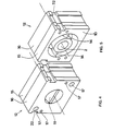
- the power supply unit 1 comprises a central channel 2, the inlet 3 of which is connected to a source of molten thermoplastic material not shown and whose outlet 4 is connected to a flat coextrusion die also not shown and a secondary channel 5 whose inlet 6 is connected to a second source of molten thermoplastic material not shown.
- the secondary channel 5 opens first into a distribution torus 7 equipped with a conventional adjustment ring 8 whose position is controllable by means of adjustment bolts 9.
- the distribution torus 7 is inclined relative to the axis of the central channel 2 and has a section which decreases progressively, the maximum section being situated opposite its supply of molten thermoplastic material and its minimum section being situated at 180 ° from the maximum section.
- the molten thermoplastic material discharged into the feed toroid 7 flows through the secondary channel in its portion 10 which surrounds the central channel 2 and is then applied to the flow of molten thermoplastic material discharged through the central channel 2.
- the flow of molten thermoplastic material of circular section delivered by the central channel 2 is spread by means of a flat 11 of suitable profile upstream of its meeting point with the flow of molten thermoplastic material delivered through secondary channel 10.
- the flat 11 is mounted in a removable part 12 coaxial with the central channel 2 and disposed in a guide duct 13 intercepting the central channel 2 and passing right through the power supply 1 at the connection from central channel 2 with secondary channel 10.
- the flat 11 is fixed in the removable part 12 by means of support fins 14.
- the removable part 12 for reasons of ease of machining the flat 11, is produced in two parts 15, 16 which are associated with each other by means of fixing devices 17.
- a second removable part 18 also comprising a flat 19 is disposed in the guide duct 13 against the removable part 12 and is held in place by a pneumatic pusher 20.
- the removable part 12 is gradually put out of service under the thrust of the removable part 18 and, when the latter is in place, the removable part 12 can be removed from the guide duct 13 by means of an extractor 21 equipped with movable jaws which can cooperate with extraction notches 22 provided in the removable part 12. This removable part 12 can then be cleaned with a view to putting it back into service later.
- the power supply unit described allows easy replacement of the flat surface ensuring the geometric modification of a flow of molten thermoplastic material flowing in the central channel.
- the power supply unit which has just been described can be the subject of numerous variant embodiments.
- the channel 2 can be of rectangular or other section.
- the guide duct 13 can be designed to contain a plurality of identical or different removable parts as regards the flat, these parts being able to be successively put into service.
- the removable parts can be equipped with centering means ensuring correct commissioning and / or means ensuring perfect sealing with respect to the flows of molten thermoplastic materials delivered.
- the guide duct 13 can be equipped with heating means ensuring an adequate temperature rise of the successive removable parts before they are put into service and / or means ensuring a vacuuming of the removable parts before they are put into service.
- the power supply unit can be equipped with a plurality of devices allowing the replacement of flats on several levels and be provided with an alarm device signaling any incorrect installation of a removable part equipped with a flat .
Landscapes
- Engineering & Computer Science (AREA)
- Mechanical Engineering (AREA)
- Manufacturing & Machinery (AREA)
- Extrusion Moulding Of Plastics Or The Like (AREA)
- Formation And Processing Of Food Products (AREA)
- Extrusion Of Metal (AREA)
Claims (9)
Priority Applications (1)
| Application Number | Priority Date | Filing Date | Title |
|---|---|---|---|
| AT86200464T ATE34695T1 (de) | 1985-04-01 | 1986-03-20 | Beschickungsblock fuer eine breitschlitzkoextrudierd¨se. |
Applications Claiming Priority (2)
| Application Number | Priority Date | Filing Date | Title |
|---|---|---|---|
| FR8505029A FR2579516B1 (fr) | 1985-04-01 | 1985-04-01 | Bloc d'alimentation pour filiere plate de coextrusion |
| FR8505029 | 1985-04-01 |
Publications (2)
| Publication Number | Publication Date |
|---|---|
| EP0197581A1 EP0197581A1 (de) | 1986-10-15 |
| EP0197581B1 true EP0197581B1 (de) | 1988-06-01 |
Family
ID=9317885
Family Applications (1)
| Application Number | Title | Priority Date | Filing Date |
|---|---|---|---|
| EP86200464A Expired EP0197581B1 (de) | 1985-04-01 | 1986-03-20 | Beschickungsblock für eine Breitschlitz-Koextrudierdüse |
Country Status (6)
| Country | Link |
|---|---|
| US (1) | US4652225A (de) |
| EP (1) | EP0197581B1 (de) |
| JP (1) | JPH0657419B2 (de) |
| AT (1) | ATE34695T1 (de) |
| DE (1) | DE3660239D1 (de) |
| FR (1) | FR2579516B1 (de) |
Families Citing this family (27)
| Publication number | Priority date | Publication date | Assignee | Title |
|---|---|---|---|---|
| DE3821902A1 (de) * | 1988-06-29 | 1990-01-04 | Reifenhaeuser Masch | Anlage zum extrudieren eines mehrschichtigen stranges aus thermoplastifizierten kunststoffen |
| DE3838877A1 (de) * | 1988-11-17 | 1990-05-23 | Krupp Gmbh | Extrusionskopf |
| DE3929002A1 (de) * | 1989-09-01 | 1991-03-14 | Schmidt Erwepa Maschf | Vorrichtung zum extrudieren von kunststoff-mehrschichtfolien oder -platten |
| DE4243277C2 (de) * | 1992-12-21 | 1997-05-07 | Bayer Ag | Vorrichtung zum kontinuierlichen Herstellen von Schaumstoffbahnen, insbesondere Hartschaumstoffplatten |
| DE4334564A1 (de) * | 1993-10-11 | 1995-04-13 | Werner & Pfleiderer | Vorrichtung zur Einstellung des Massedruckes in Schneckenextrudern |
| US5679379A (en) * | 1995-01-09 | 1997-10-21 | Fabbricante; Anthony S. | Disposable extrusion apparatus with pressure balancing modular die units for the production of nonwoven webs |
| US5577437A (en) * | 1995-11-06 | 1996-11-26 | General Mills, Inc. | Cooker die removably securing mechanism |
| US5902540A (en) * | 1996-10-08 | 1999-05-11 | Illinois Tool Works Inc. | Meltblowing method and apparatus |
| US6680021B1 (en) | 1996-07-16 | 2004-01-20 | Illinois Toolworks Inc. | Meltblowing method and system |
| US5904298A (en) * | 1996-10-08 | 1999-05-18 | Illinois Tool Works Inc. | Meltblowing method and system |
| US5780067A (en) * | 1996-09-10 | 1998-07-14 | Extrusion Dies, Inc. | Adjustable coextrusion feedblock |
| US5882573A (en) * | 1997-09-29 | 1999-03-16 | Illinois Tool Works Inc. | Adhesive dispensing nozzles for producing partial spray patterns and method therefor |
| US6051180A (en) * | 1998-08-13 | 2000-04-18 | Illinois Tool Works Inc. | Extruding nozzle for producing non-wovens and method therefor |
| US6200635B1 (en) | 1998-08-31 | 2001-03-13 | Illinois Tool Works Inc. | Omega spray pattern and method therefor |
| US6602554B1 (en) | 2000-01-14 | 2003-08-05 | Illinois Tool Works Inc. | Liquid atomization method and system |
| US6152021A (en) * | 2000-01-19 | 2000-11-28 | General Mills, Inc. | Cooker die and rotary cutter removably securing mechanism |
| US6626206B1 (en) | 2000-01-20 | 2003-09-30 | Extrusion Dies, Inc. | Feedblock for adjusting the dimensions of a set of co-extruded layers of a multi-layer sheet |
| US6167798B1 (en) | 2000-04-19 | 2001-01-02 | General Mills, Inc. | Cooker die and rotary cutter removably securing mechanism |
| US6189439B1 (en) | 2000-05-25 | 2001-02-20 | General Mills, Inc. | Cooker die and rotary cutter removably securing mechanism |
| US6767198B2 (en) * | 2001-10-17 | 2004-07-27 | General Mills, Inc. | Rotary cutter assembly |
| JP4042096B2 (ja) * | 2002-04-12 | 2008-02-06 | 富士フイルム株式会社 | 樹脂成形品の製造装置及び方法 |
| JP3944846B2 (ja) * | 2002-12-03 | 2007-07-18 | 富士フイルム株式会社 | 樹脂膜の形成方法及び装置 |
| USD550261S1 (en) | 2006-12-13 | 2007-09-04 | Nordson Corporation | Adhesive dispensing nozzle |
| US7798434B2 (en) * | 2006-12-13 | 2010-09-21 | Nordson Corporation | Multi-plate nozzle and method for dispensing random pattern of adhesive filaments |
| USD588617S1 (en) | 2008-04-14 | 2009-03-17 | Nordson Corporation | Nozzle assembly |
| US8074902B2 (en) | 2008-04-14 | 2011-12-13 | Nordson Corporation | Nozzle and method for dispensing random pattern of adhesive filaments |
| CN102658636B (zh) * | 2012-04-06 | 2014-08-13 | 宁波市天普橡胶科技有限公司 | 一种挤出成型复合橡胶管外胶层的真空复合装置 |
Family Cites Families (9)
| Publication number | Priority date | Publication date | Assignee | Title |
|---|---|---|---|---|
| US2897541A (en) * | 1956-12-03 | 1959-08-04 | Nixon Nitration Works | Apparatus for extruding sheets with striped pattern |
| DE1198537B (de) * | 1963-05-15 | 1965-08-12 | Barmag Barmer Maschf | Schnellwechsel-Doppellochplatte fuer Schneckenstrangpressen |
| US3315306A (en) * | 1965-10-15 | 1967-04-25 | Dow Chemical Co | Apparatus for the production of multilayer film |
| DE1665805B1 (de) * | 1966-11-12 | 1971-09-23 | Siemens Ag | Spritzkopf fuer strangpressen zur herstellung von isolier huellen fuer elektrische leiter |
| FR1531130A (fr) * | 1967-07-13 | 1968-06-28 | Dow Chemical Co | Adapteur d'extrusion |
| US3860372A (en) * | 1971-02-26 | 1975-01-14 | Dow Chemical Co | Adjustable feedblock for encapsulated multilayer extrusion |
| DE2414178A1 (de) * | 1974-03-23 | 1975-10-09 | Aluminium Walzwerke Singen | Verfahren zur herstellung von verbundprofilen sowie vorrichtung zu dessen durchfuehrung |
| NL7601569A (nl) * | 1975-04-17 | 1976-10-19 | Mobil Oil Corp | Van een filterzeef voorziene extrusie-inrichting voor polymeren. |
| DE3013038C2 (de) * | 1980-04-03 | 1983-02-03 | Werner & Pfleiderer, 7000 Stuttgart | Siebwechselvorrichtung für Extruder |
-
1985
- 1985-04-01 FR FR8505029A patent/FR2579516B1/fr not_active Expired
-
1986
- 1986-03-20 EP EP86200464A patent/EP0197581B1/de not_active Expired
- 1986-03-20 DE DE8686200464T patent/DE3660239D1/de not_active Expired
- 1986-03-20 AT AT86200464T patent/ATE34695T1/de not_active IP Right Cessation
- 1986-03-27 US US06/845,118 patent/US4652225A/en not_active Expired - Lifetime
- 1986-03-28 JP JP61070632A patent/JPH0657419B2/ja not_active Expired - Fee Related
Also Published As
| Publication number | Publication date |
|---|---|
| JPS61227013A (ja) | 1986-10-09 |
| FR2579516B1 (fr) | 1987-06-12 |
| DE3660239D1 (en) | 1988-07-07 |
| JPH0657419B2 (ja) | 1994-08-03 |
| ATE34695T1 (de) | 1988-06-15 |
| EP0197581A1 (de) | 1986-10-15 |
| FR2579516A1 (fr) | 1986-10-03 |
| US4652225A (en) | 1987-03-24 |
Similar Documents
| Publication | Publication Date | Title |
|---|---|---|
| EP0197581A1 (de) | Beschickungsblock für eine Breitschlitz-Koextrudierdüse | |
| CA1119392A (fr) | Dispositif pour la fabrication de corps a structure alveolaire par extrusion d'une matiere ceramique, et procede de fabrication dudit dispositif | |
| EP0171309B1 (de) | Vorbereitung eines Kunststoffes zum Extrudieren, insbesondere in Form eines kalibrierten Bandes zur Verwendung als Verbindungsmaterial und als Zwischeneinlage in Mehrfachverglasungen | |
| EP0677159B1 (de) | Mehrschichtrohr und extruderdüse für seine herstellung | |
| EP3325248B1 (de) | Vorrichtung und verfahren zur reinigung eines extruders für elastomermischungen | |
| EP0428464B1 (de) | Zylinder für Einzel- oder Doppelrollenstranggiessvorrichtung | |
| EP0161210B1 (de) | Zuführeinrichtung für Drehautomaten mit Achsenlagern | |
| EP0236645B1 (de) | Vorrichtung und Verfahren zum Extrudieren von Kunststoffrohren mit mehrschichtigen Wänden | |
| EP3383617B1 (de) | Kalandriereinrichtung für verstärkungslagen für reifen | |
| EP3558625B1 (de) | Extrusionsanlage mit einem verbesserten extrusionskopf | |
| CA2743401C (fr) | Bague pour palier hydrostatique ou hydrodynamique, machine hydraulique equipee d'une telle bague et procede de montage d'une telle bague sur un arbre | |
| FR2994121A1 (fr) | Procede de fabrication d'un outillage de moulage destine au moulage d'une piece en materiau composite | |
| EP0245314B1 (de) | Vorrichtung zur veränderung der farbe während des strangpressens eines mantels um einen leiter | |
| EP3853001B1 (de) | Koextrusionsmaschine für elastomere verbindungen und verfahren zur herstellung einer profilelementeleiste | |
| FR2697774A1 (fr) | Filière plate pour l'extrusion de film, feuille ou plaque en matière synthétique. | |
| EP3558624B1 (de) | Extrusionsausrüstung mit verbessertem extruderkopf | |
| BE1001610A4 (fr) | Filiere d'extrudeuse pour la fabrication d'une feuille soufflee multicouche. | |
| FR2976210A1 (fr) | Ensemble et methode de fabrication d'une gaine tubulaire | |
| EP3302911B1 (de) | Vorrichtung mit verbesserten dichtungsmitteln zur verteilung von thermoplastischem material | |
| EP4267365B1 (de) | Extrusionsanlage mit unterirdischer übergabe des werkzeugmoduls | |
| FR2483842A1 (fr) | Procede et dipsositif d'extrusion a plusieurs etages superposes ou " en cascades " | |
| EP1100672B1 (de) | Vorrichtung zur regelung der dicke eines vorformlings in einer extrusionsblasformmaschine | |
| EP4025399A1 (de) | Verfahren und maschine zum schneiden von stoffelementen | |
| FR3020307A1 (fr) | Dispositif de pose de fibres | |
| RU2236337C2 (ru) | Способ изготовления пресс-формы-холодильника-токоподвода к агрегату контактной стыковой сварки |
Legal Events
| Date | Code | Title | Description |
|---|---|---|---|
| PUAI | Public reference made under article 153(3) epc to a published international application that has entered the european phase |
Free format text: ORIGINAL CODE: 0009012 |
|
| AK | Designated contracting states |
Kind code of ref document: A1 Designated state(s): AT BE CH DE FR GB IT LI NL SE |
|
| 17P | Request for examination filed |
Effective date: 19870403 |
|
| 17Q | First examination report despatched |
Effective date: 19871105 |
|
| ITF | It: translation for a ep patent filed | ||
| GRAA | (expected) grant |
Free format text: ORIGINAL CODE: 0009210 |
|
| AK | Designated contracting states |
Kind code of ref document: B1 Designated state(s): AT BE CH DE FR GB IT LI NL SE |
|
| REF | Corresponds to: |
Ref document number: 34695 Country of ref document: AT Date of ref document: 19880615 Kind code of ref document: T |
|
| REF | Corresponds to: |
Ref document number: 3660239 Country of ref document: DE Date of ref document: 19880707 |
|
| GBT | Gb: translation of ep patent filed (gb section 77(6)(a)/1977) | ||
| PLBE | No opposition filed within time limit |
Free format text: ORIGINAL CODE: 0009261 |
|
| STAA | Information on the status of an ep patent application or granted ep patent |
Free format text: STATUS: NO OPPOSITION FILED WITHIN TIME LIMIT |
|
| 26N | No opposition filed | ||
| ITTA | It: last paid annual fee | ||
| REG | Reference to a national code |
Ref country code: FR Ref legal event code: CD |
|
| ITPR | It: changes in ownership of a european patent |
Owner name: CAMBIO RAGIONE SOCIALE;SOLVAY |
|
| REG | Reference to a national code |
Ref country code: CH Ref legal event code: PFA Free format text: SOLVAY (SOCIETE ANONYME) |
|
| NLT1 | Nl: modifications of names registered in virtue of documents presented to the patent office pursuant to art. 16 a, paragraph 1 |
Owner name: SOLVAY (SOCIETE ANONYME) TE BRUSSEL, BELGIE. |
|
| EAL | Se: european patent in force in sweden |
Ref document number: 86200464.5 |
|
| REG | Reference to a national code |
Ref country code: GB Ref legal event code: IF02 |
|
| PGFP | Annual fee paid to national office [announced via postgrant information from national office to epo] |
Ref country code: GB Payment date: 20040317 Year of fee payment: 19 |
|
| PGFP | Annual fee paid to national office [announced via postgrant information from national office to epo] |
Ref country code: BE Payment date: 20040518 Year of fee payment: 19 |
|
| PGFP | Annual fee paid to national office [announced via postgrant information from national office to epo] |
Ref country code: NL Payment date: 20050303 Year of fee payment: 20 |
|
| PGFP | Annual fee paid to national office [announced via postgrant information from national office to epo] |
Ref country code: SE Payment date: 20050304 Year of fee payment: 20 |
|
| PGFP | Annual fee paid to national office [announced via postgrant information from national office to epo] |
Ref country code: FR Payment date: 20050308 Year of fee payment: 20 |
|
| PGFP | Annual fee paid to national office [announced via postgrant information from national office to epo] |
Ref country code: AT Payment date: 20050311 Year of fee payment: 20 |
|
| PGFP | Annual fee paid to national office [announced via postgrant information from national office to epo] |
Ref country code: CH Payment date: 20050316 Year of fee payment: 20 |
|
| PGFP | Annual fee paid to national office [announced via postgrant information from national office to epo] |
Ref country code: DE Payment date: 20050317 Year of fee payment: 20 |
|
| PG25 | Lapsed in a contracting state [announced via postgrant information from national office to epo] |
Ref country code: GB Free format text: LAPSE BECAUSE OF NON-PAYMENT OF DUE FEES Effective date: 20050320 |
|
| PGFP | Annual fee paid to national office [announced via postgrant information from national office to epo] |
Ref country code: IT Payment date: 20050330 Year of fee payment: 20 |
|
| PG25 | Lapsed in a contracting state [announced via postgrant information from national office to epo] |
Ref country code: BE Free format text: LAPSE BECAUSE OF NON-PAYMENT OF DUE FEES Effective date: 20050331 |
|
| BERE | Be: lapsed |
Owner name: *SOLVAY Effective date: 20050331 |
|
| GBPC | Gb: european patent ceased through non-payment of renewal fee |
Effective date: 20050320 |
|
| PG25 | Lapsed in a contracting state [announced via postgrant information from national office to epo] |
Ref country code: NL Free format text: LAPSE BECAUSE OF EXPIRATION OF PROTECTION Effective date: 20060320 |
|
| EUG | Se: european patent has lapsed | ||
| NLV7 | Nl: ceased due to reaching the maximum lifetime of a patent |
Effective date: 20060320 |
|
| BERE | Be: lapsed |
Owner name: *SOLVAY Effective date: 20050331 |