EP0198585A2 - Caisse de véhicule à emplacement asymétrique des sièges avant du conducteur et du passager - Google Patents
Caisse de véhicule à emplacement asymétrique des sièges avant du conducteur et du passager Download PDFInfo
- Publication number
- EP0198585A2 EP0198585A2 EP86301536A EP86301536A EP0198585A2 EP 0198585 A2 EP0198585 A2 EP 0198585A2 EP 86301536 A EP86301536 A EP 86301536A EP 86301536 A EP86301536 A EP 86301536A EP 0198585 A2 EP0198585 A2 EP 0198585A2
- Authority
- EP
- European Patent Office
- Prior art keywords
- seat
- vehicle body
- driver
- center line
- front passenger
- Prior art date
- Legal status (The legal status is an assumption and is not a legal conclusion. Google has not performed a legal analysis and makes no representation as to the accuracy of the status listed.)
- Withdrawn
Links
- 230000005540 biological transmission Effects 0.000 claims abstract description 10
- 230000003467 diminishing effect Effects 0.000 abstract 1
- 230000008901 benefit Effects 0.000 description 4
- 238000010276 construction Methods 0.000 description 3
- 230000009286 beneficial effect Effects 0.000 description 2
- 229910000831 Steel Inorganic materials 0.000 description 1
- 230000004075 alteration Effects 0.000 description 1
- 230000000694 effects Effects 0.000 description 1
- 230000004313 glare Effects 0.000 description 1
- 238000004519 manufacturing process Methods 0.000 description 1
- 230000004048 modification Effects 0.000 description 1
- 238000012986 modification Methods 0.000 description 1
- 239000010959 steel Substances 0.000 description 1
Images

Classifications
-
- B—PERFORMING OPERATIONS; TRANSPORTING
- B62—LAND VEHICLES FOR TRAVELLING OTHERWISE THAN ON RAILS
- B62D—MOTOR VEHICLES; TRAILERS
- B62D21/00—Understructures, i.e. chassis frame on which a vehicle body may be mounted
-
- B—PERFORMING OPERATIONS; TRANSPORTING
- B60—VEHICLES IN GENERAL
- B60N—SEATS SPECIALLY ADAPTED FOR VEHICLES; VEHICLE PASSENGER ACCOMMODATION NOT OTHERWISE PROVIDED FOR
- B60N2/00—Seats specially adapted for vehicles; Arrangement or mounting of seats in vehicles
- B60N2/005—Arrangement or mounting of seats in vehicles, e.g. dismountable auxiliary seats
- B60N2/01—Arrangement of seats relative to one another
Definitions
- the present invention relates to a vehicle body, and more specifically relates to a vehicle body in which the front driver's seat and the front passenger's seat are asymmetrically disposed with respect to the central line of the vehicle body.
- the vehicle in question is of the so called right hand drive configuration, in which the driver sits on the right side thereof and a front passenger optionally sits on the left side thereof; but this should not be considered as limitative, but as applying equally to a left hand drive configuration type vehicle, mutatis mutandis.
- a vehicle body has been built in a symmetrical fashion with respect to its central line, i.e. with respect to the line drawn as connecting the middle points of the front and the rear axle lines of the vehicle.
- the interior arrangements of the vehicle body have been conventionally symmetrical about the center line, and in particular, in the case of a vehicle with so called bucket seats in which the driver's seat and the front passenger's seat are separately provided, the two front seats have been symmetrically positioned: in other words, the driver's seat and the front passenger's seat are located at equal distances on opposite sides of the vehicle center line.
- the spaces allocated to the driver and to the front seat passenger have been substantially identical in form and size, being mirror images of one another.
- the present invention is based upon the recognition that, since a passenger in the front seat is much less active than the driver, such a passenger is less prone to becoming cramped than the driver. Further, cramping of such a passenger is intrinsically less important than cramping of the driver, because the comfort of the driver is in any case more important than that of the passenger since the driver bears the responsibility of controlling the vehicle and also typically is the owner of the vehicle. Thus, the present inventive entity has come to question the conventional wisdom of allocating similar spaces tc the driver and to the front seat passenger.
- a vehicle body comprising a floor and two sides and defining a longitudinal center line (Ll) midway between its two sides, comprising:
- the passenger compartment arrangement is such as to maximize effectiveness of space utilization.
- a vehicle body in which the driver is enabled to sit squarely opposite the control pedals without any slanting relative to the longitudinal direction of the vehicle, which is very beneficial from the point of view of good control.
- a central floor tunnel may be formed along the longitudinal center line of the vehicle body: and in this case a hand brake lever, a transmission shift lever and so on may be fitted in a position laterally offset from the center of the floor tunnel towards the front passenger's seat.
- a floor tunnel may be formed offset from the longitudinal center line of the vehicle body towards the front passenger's seat.
- a hand brake lever, a transmission shift lever and so on may be fitted at laterally central position on the floor tunnel.
- a driver's side sun visor is wider than a passenger's side sun visor and the mid point between their inner ends is offset towards the front passenger's seat from the longitudinal center line of the vehicle body; and a rear view mirror may be fitted to a mid point between the inner ends of the sun visors.
- the effect is obtained of concealing as much as possible the essential asymmetry of the interior arrangements of the vehicle from the eye of the beholder.
- Figure 1 shows the first preferred embodiment of the vehicle body of the present invention in schematic plan view
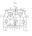
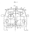
- Figure 2 shows the vehicle body in schematic view as seen from the front thereof.
- This vehicle body 1 which is a body for a right hand drive configuration type vehicle
- the center line of the body 1, about which the body 1 is symmetrical, is shown in the figures by the line L1
- the front wheels 2 and the rear wheels 3 are similarly symmetrically disposed on either side of this center line L1 at equal distances therefrom.
- the center line L1 connects the middle points of the front and the rear axle lines (not particularly shown) of the vehicle body.
- the body 1 may, for example, be made by press forming steel plate in a so called monocoque structure.
- the front seats of the vehicle are denoted as 4 and 5: the seat 4 is a seat for the vehicle driver, and is on the right side of the vehicle body, while the seat 5 is a seat for a passenger and is on the left side of the vehicle body.
- These seats 4 and 5 are, in the first preferred embodiment, of the same dimensions and configuration but are mirror images of one another, and are attached to the floor of the vehicle body 1 on either side of the center line L1.
- the distance between the center line L3 of the driver's seat 4 and the center line L1 of the vehicle body 1 to which the center line L3 is parallel, denoted as d1, is substantially less, than the distance between the center line L4 of the passenger's seat 5 and the center line L1 of the vehicle body 1 to which the center line L4 is similarly parallel, denoted as d2; in other words, the center line L2 defined between the driver's seat 4 and the passenger's seat 5 (which is equidistant between the parallel center lines L3 and L4 of the seats and is parallel thereto) is offset by a substantial distance (in fact approximately equal to half of the difference between d2 and d1 ) from the center line L1 of the vehicle body, while extending parallel thereto.
- a brake pedal 6 Squarely in front of the driver's seat 4, approximately on the center line L3 thereof, there is positioned a brake pedal 6, and a clutch pedal 7 (since this exemplary vehicle is a manual transmission type vehicle) is provided on the left of the brake pedal 6 while an accelerator pedal 8 is provided on the right of the brake pedal 6, in a per se conventional arrangement.
- the distance between the clutch pedal 7 and the brake pedal 6 is approximately equal to the distance between the accelerator pedal 8 and the brake pedal 6.
- a floor tunnel 20 is formed on the floor of the vehicle body 1 extending in-the longitudinal direction thereof, with the center line L2 between the driver's seat 4 and the passenger's seat 5 passing along the center of the floor tunnel 20; and a shift lever 9 projects upward from an intermediate point along the tunnel 20.
- this shift lever 9 is connected via rods and levers or the like to control the transmission of the vehicle, although these arrangements are not particularly shown.
- the knob 9a of this shift lever 9 is substantially equidistant between the driver's seat 4 and the passenger's seat 5.
- a hand brake lever 10 projects upward from another intermediate point along the tunnel 20, to the rear of the shift lever 9, and similarly this hand brake lever 10 is connected via a cable or the like to control the parking brake system of the vehicle, although these arrangements are not particularly shown either.
- the grip portion 10a of this parking brake lever 10 is similarly substantially equidistant between the driver's seat 4 and the passenger's seat 5.
- the shift lever 9 and the hand brake lever 10 are set to be symmetrical about the center line L2 between the driver's sest 4 and the passenger's seat 5, not about the center line L1 of the vehicle body
- a rear view mirror 11 which is substantially symmetric in shape, is mounted to a point on the ceiling of the vehicle body 1 generally along the top edge of the front windscreen opening thereof and laterally located substantially on the center line L2 between the driver's seat 4-and the passenger's seat 5.
- a driver's side sun visor 12 is pivoted by a pivot arrangement 12a of a per se known sort to a point on the ceiling of the vehicle body 1 generally at the top right corner of the front windscreen opening thereof, so as to be selectively turnable downwards so as to shield the eyes of a driver 4 from glare coming from the upper front and the upper side directions; and, similarly, a passenger's side sun visor 13 is pivoted by a pivot arrangement 13a also of a per se known sort to a point on the ceiling of the vehicle body 1 generally at the top left corner of the front windscreen opening thereof.
- the distance between the pivot arrangement 12a for the driver's side sun visor 12 and the center line L1 of the vehicle body 1 is set to be substantially equal to the distance between the pivot arrangement 13a for the passenger's side sun visor 13 and the center line L1 of the vehicle body 1; in other words, the pivot points of the sun visors 12 and 13 are set to be symmetrical about the center line L1 of the vehicle body 1, not about the center line L2 between the driver's seat 4 and the passenger's seat 5.
- the driver's side sun visor 12 is substantially longer than the passenger's side sun visor 13 so that the inner end of the driver's side sun visor 12 is located at approximately the same distance from the center line L2 between the driver's seat 4 and the passenger's seat 5 as is the inner end of the passenger's side sun visor 13; in other words, the inner ends of the sun visors 12 and 13 are set to be symmetrical about the center line L2 between the driver's seat 4 and the passenger's seat 5, not about the center line L1 of the vehicle body 1.
- the driver's side sun visor 12 and the passenger's side sun visor 13 are constructed to have substantially the same vertical dimensions.
- the rear seat 15 of the vehicle is constructed as a so called bench seat in which the right side and the left side seats are integrally formed in a symmetric manner, and this rear seat 15 is so mounted in the passenger compartment that it is symmetrically located about the center line L1 of the vehicle body 1, not about the center line L2 between the driver's seat 4 and the passenger's seat 5.
- a vehicle body in which the passenger compartment arrangement is such as to maximize effectiveness of space utilization and is such as to maximize driver comfort. This is because more space is allocated for the driver, who is required to be active and to control the vehicle, than is allocated for the passenger, whose role is an essentially passive one.
- the interior arrangements of the passenger compartment are arranged as explained above, the essential asymmetry of the passenger compartment is concealed as much as practicable from the eye of the beholder.
- the driver is enabled to sit squarely opposite the control pedals without any slanting relative to the longitudinal direction of the vehicle, and accordingly can look straight ahead in the direction of the vehicle's travel without being forced to look sideways. According to this, it has become possible to align the central line L3 of the driver's seat 4 substantially parallel to the longitudinal axis L1 of the vehicle body. Although this is not to be considered as essential to the present invention, it is a useful and desirable specialization thereof.
- the driver's seat 4 was made similar but enantiomorphic to the front passenger's seat 5, and in particular was made of substantially the same width; but this is not to be considered as limitative of the present invention.
- the driver's seat 4 is made to be wider than the front passenger's seat 5.
- this second preferred embodiment is similar to the first preferred embodiment described hereinabove, and the same advantages and benefits arise therefrom, some in greater measure.
- the floor tunnel 20' may be provided on the center line L of the vehicle while the front seats 4 and 5 are arranged symmetric all with respect to the center line L2 of the two front seats 4 and 5 which is offset toward the passenger's seat 5.
- the hand brake lever 10 and the transmission shift lever 9 are accordingly fitted to coincide with the center line L2 of the two front seats 4 and 5, therefore, being substantially offset from the center of the floor tunnel 20'.
- This embodiment has the advantage of complete symmetry of the vehicle body, in addition to the advantages of the previous embodiments. By having the vehicle body substantially symmetrical, the vehicle body may be readily adapted to manufacture of vehicles of both right and left hand drive configurations.
Landscapes
- Engineering & Computer Science (AREA)
- Transportation (AREA)
- Mechanical Engineering (AREA)
- Aviation & Aerospace Engineering (AREA)
- Chemical & Material Sciences (AREA)
- Combustion & Propulsion (AREA)
- Body Structure For Vehicles (AREA)
- Seats For Vehicles (AREA)
Applications Claiming Priority (2)
| Application Number | Priority Date | Filing Date | Title |
|---|---|---|---|
| JP60081153A JPS61238540A (ja) | 1985-04-16 | 1985-04-16 | 自動車の車室内レイアウト構造 |
| JP81153/85 | 1985-04-16 |
Publications (2)
| Publication Number | Publication Date |
|---|---|
| EP0198585A2 true EP0198585A2 (fr) | 1986-10-22 |
| EP0198585A3 EP0198585A3 (fr) | 1989-03-08 |
Family
ID=13738488
Family Applications (1)
| Application Number | Title | Priority Date | Filing Date |
|---|---|---|---|
| EP86301536A Withdrawn EP0198585A3 (fr) | 1985-04-16 | 1986-03-05 | Caisse de véhicule à emplacement asymétrique des sièges avant du conducteur et du passager |
Country Status (4)
| Country | Link |
|---|---|
| US (1) | US4668003A (fr) |
| EP (1) | EP0198585A3 (fr) |
| JP (1) | JPS61238540A (fr) |
| KR (1) | KR860008066A (fr) |
Families Citing this family (2)
| Publication number | Priority date | Publication date | Assignee | Title |
|---|---|---|---|---|
| CN103370259B (zh) * | 2011-01-27 | 2016-08-17 | 姜汉求 | 不对称型汽车 |
| FR2998855B1 (fr) * | 2012-12-05 | 2016-11-25 | Peugeot Citroen Automobiles Sa | Vehicule automobile dont une carrosserie a un habitacle avec un siege conducteur et un siege passager avant disposes de front et de facon dissymetrique rapport a un axe median de la carrosserie. |
Family Cites Families (7)
| Publication number | Priority date | Publication date | Assignee | Title |
|---|---|---|---|---|
| DE1430832A1 (de) * | 1963-07-23 | 1969-09-04 | Daimler Benz Ag | Personenkraftwagen,insbesondere Kleinwagen mit Heckmotor |
| DE1505389A1 (de) * | 1964-04-22 | 1969-10-09 | Girolamo Bargagli Bardi Bandin | Kraftfahrzeug mit verbesserter Parkfaehigkeit |
| DE2055469A1 (de) * | 1970-11-02 | 1972-05-10 | Linnhoff, Ingrid; Linnhoff, Fritz, DipL-Ing.; 2281 Morsum | Kombiniertes Transportsystem mit Kraftwagen und Eisenbahnwaggons |
| GB1333348A (en) * | 1972-08-17 | 1973-10-10 | Pedrick A P | Automobile construction |
| SE417183B (sv) * | 1977-04-14 | 1981-03-02 | Volvo Ab | Sidokollisionsskydd i motorfordon |
| IT1138285B (it) * | 1981-04-30 | 1986-09-17 | Renato Monzini | Autoveicolo,per il trasporto di persone |
| JPS5833533A (ja) * | 1981-08-22 | 1983-02-26 | Nissan Motor Co Ltd | 座席 |
-
1985
- 1985-04-16 JP JP60081153A patent/JPS61238540A/ja active Pending
-
1986
- 1986-02-20 KR KR1019860001213A patent/KR860008066A/ko not_active Withdrawn
- 1986-03-05 EP EP86301536A patent/EP0198585A3/fr not_active Withdrawn
- 1986-03-10 US US06/837,714 patent/US4668003A/en not_active Expired - Fee Related
Also Published As
| Publication number | Publication date |
|---|---|
| EP0198585A3 (fr) | 1989-03-08 |
| KR860008066A (ko) | 1986-11-12 |
| JPS61238540A (ja) | 1986-10-23 |
| US4668003A (en) | 1987-05-26 |
Similar Documents
| Publication | Publication Date | Title |
|---|---|---|
| JPS6035681A (ja) | 車両における変速機装置 | |
| JPH028855Y2 (fr) | ||
| JP3085585B2 (ja) | 車 体 | |
| US4668003A (en) | Vehicle body with asymmetric location of front driver and passenger seats | |
| JPH0514946Y2 (fr) | ||
| US4212367A (en) | Manual lever for a vehicle | |
| JPS5812871A (ja) | 自動車の車体構造 | |
| JPH0327911Y2 (fr) | ||
| JPH05221342A (ja) | 自動車の車体フロア構造 | |
| US12485976B2 (en) | Work vehicle | |
| JPH0547751Y2 (fr) | ||
| JPS62163561U (fr) | ||
| JP2566561Y2 (ja) | キャブオーバ型車両のステアリングコラムカバー装置 | |
| JPH0349176U (fr) | ||
| JP2561397Y2 (ja) | 車両の上部車体構造 | |
| JP2539500Y2 (ja) | ダブルキャブ型トラック | |
| JPH0420675Y2 (fr) | ||
| JPS615273U (ja) | 自動車の下部車体構造 | |
| JPH0537910Y2 (fr) | ||
| JPH0659811B2 (ja) | 自動車の車体構造 | |
| JPH0717616U (ja) | 自動車の死角を無くしたフロントガラス | |
| JPS644631Y2 (fr) | ||
| JPH0710949Y2 (ja) | リアシートサイドバック | |
| JPH0431843Y2 (fr) | ||
| JPH0612234U (ja) | 車両のサイドブレーキ装置 |
Legal Events
| Date | Code | Title | Description |
|---|---|---|---|
| PUAI | Public reference made under article 153(3) epc to a published international application that has entered the european phase |
Free format text: ORIGINAL CODE: 0009012 |
|
| AK | Designated contracting states |
Kind code of ref document: A2 Designated state(s): DE FR GB IT |
|
| PUAL | Search report despatched |
Free format text: ORIGINAL CODE: 0009013 |
|
| AK | Designated contracting states |
Kind code of ref document: A3 Designated state(s): DE FR GB IT |
|
| STAA | Information on the status of an ep patent application or granted ep patent |
Free format text: STATUS: THE APPLICATION IS DEEMED TO BE WITHDRAWN |
|
| 18D | Application deemed to be withdrawn |
Effective date: 19890909 |
|
| RIN1 | Information on inventor provided before grant (corrected) |
Inventor name: ISHIZAKI, HIROSHI Inventor name: HAYASHI, HIROKI |