EP0199142A2 - Dispositif de pulvérisation manuel - Google Patents
Dispositif de pulvérisation manuel Download PDFInfo
- Publication number
- EP0199142A2 EP0199142A2 EP86104325A EP86104325A EP0199142A2 EP 0199142 A2 EP0199142 A2 EP 0199142A2 EP 86104325 A EP86104325 A EP 86104325A EP 86104325 A EP86104325 A EP 86104325A EP 0199142 A2 EP0199142 A2 EP 0199142A2
- Authority
- EP
- European Patent Office
- Prior art keywords
- pump
- piston
- valve
- channel
- outlet
- Prior art date
- Legal status (The legal status is an assumption and is not a legal conclusion. Google has not performed a legal analysis and makes no representation as to the accuracy of the status listed.)
- Granted
Links
- 239000007921 spray Substances 0.000 title 1
- 238000009423 ventilation Methods 0.000 claims description 6
- 238000005086 pumping Methods 0.000 description 5
- 238000011161 development Methods 0.000 description 3
- 230000018109 developmental process Effects 0.000 description 3
- 230000001154 acute effect Effects 0.000 description 2
- 230000000903 blocking effect Effects 0.000 description 2
- 230000006835 compression Effects 0.000 description 2
- 238000007906 compression Methods 0.000 description 2
- 238000010276 construction Methods 0.000 description 2
- 230000005484 gravity Effects 0.000 description 2
- 238000007789 sealing Methods 0.000 description 2
- 229910000831 Steel Inorganic materials 0.000 description 1
- 238000005273 aeration Methods 0.000 description 1
- 238000007599 discharging Methods 0.000 description 1
- 230000000694 effects Effects 0.000 description 1
- 238000009434 installation Methods 0.000 description 1
- 238000000034 method Methods 0.000 description 1
- 230000000149 penetrating effect Effects 0.000 description 1
- 230000000284 resting effect Effects 0.000 description 1
- 239000010959 steel Substances 0.000 description 1
- 230000007704 transition Effects 0.000 description 1
Images



Classifications
-
- B—PERFORMING OPERATIONS; TRANSPORTING
- B05—SPRAYING OR ATOMISING IN GENERAL; APPLYING FLUENT MATERIALS TO SURFACES, IN GENERAL
- B05B—SPRAYING APPARATUS; ATOMISING APPARATUS; NOZZLES
- B05B11/00—Single-unit hand-held apparatus in which flow of contents is produced by the muscular force of the operator at the moment of use
- B05B11/0005—Components or details
- B05B11/0059—Components or details allowing operation in any orientation, e.g. for discharge in inverted position
-
- B—PERFORMING OPERATIONS; TRANSPORTING
- B05—SPRAYING OR ATOMISING IN GENERAL; APPLYING FLUENT MATERIALS TO SURFACES, IN GENERAL
- B05B—SPRAYING APPARATUS; ATOMISING APPARATUS; NOZZLES
- B05B11/00—Single-unit hand-held apparatus in which flow of contents is produced by the muscular force of the operator at the moment of use
- B05B11/01—Single-unit hand-held apparatus in which flow of contents is produced by the muscular force of the operator at the moment of use characterised by the means producing the flow
- B05B11/10—Pump arrangements for transferring the contents from the container to a pump chamber by a sucking effect and forcing the contents out through the dispensing nozzle
- B05B11/1001—Piston pumps
-
- B—PERFORMING OPERATIONS; TRANSPORTING
- B05—SPRAYING OR ATOMISING IN GENERAL; APPLYING FLUENT MATERIALS TO SURFACES, IN GENERAL
- B05B—SPRAYING APPARATUS; ATOMISING APPARATUS; NOZZLES
- B05B11/00—Single-unit hand-held apparatus in which flow of contents is produced by the muscular force of the operator at the moment of use
- B05B11/01—Single-unit hand-held apparatus in which flow of contents is produced by the muscular force of the operator at the moment of use characterised by the means producing the flow
- B05B11/10—Pump arrangements for transferring the contents from the container to a pump chamber by a sucking effect and forcing the contents out through the dispensing nozzle
- B05B11/1001—Piston pumps
- B05B11/1016—Piston pumps the outlet valve having a valve seat located downstream a movable valve element controlled by a pressure actuated controlling element
-
- B—PERFORMING OPERATIONS; TRANSPORTING
- B05—SPRAYING OR ATOMISING IN GENERAL; APPLYING FLUENT MATERIALS TO SURFACES, IN GENERAL
- B05B—SPRAYING APPARATUS; ATOMISING APPARATUS; NOZZLES
- B05B11/00—Single-unit hand-held apparatus in which flow of contents is produced by the muscular force of the operator at the moment of use
- B05B11/01—Single-unit hand-held apparatus in which flow of contents is produced by the muscular force of the operator at the moment of use characterised by the means producing the flow
- B05B11/10—Pump arrangements for transferring the contents from the container to a pump chamber by a sucking effect and forcing the contents out through the dispensing nozzle
- B05B11/1042—Components or details
- B05B11/1073—Springs
- B05B11/1074—Springs located outside pump chambers
-
- B—PERFORMING OPERATIONS; TRANSPORTING
- B67—OPENING, CLOSING OR CLEANING BOTTLES, JARS OR SIMILAR CONTAINERS; LIQUID HANDLING
- B67D—DISPENSING, DELIVERING OR TRANSFERRING LIQUIDS, NOT OTHERWISE PROVIDED FOR
- B67D7/00—Apparatus or devices for transferring liquids from bulk storage containers or reservoirs into vehicles or into portable containers, e.g. for retail sale purposes
- B67D7/06—Details or accessories
- B67D7/58—Arrangements of pumps
- B67D7/60—Arrangements of pumps manually operable
-
- B—PERFORMING OPERATIONS; TRANSPORTING
- B67—OPENING, CLOSING OR CLEANING BOTTLES, JARS OR SIMILAR CONTAINERS; LIQUID HANDLING
- B67D—DISPENSING, DELIVERING OR TRANSFERRING LIQUIDS, NOT OTHERWISE PROVIDED FOR
- B67D7/00—Apparatus or devices for transferring liquids from bulk storage containers or reservoirs into vehicles or into portable containers, e.g. for retail sale purposes
- B67D7/06—Details or accessories
- B67D7/58—Arrangements of pumps
- B67D7/70—Arrangements of pumps of two or more pumps in series or parallel
-
- F—MECHANICAL ENGINEERING; LIGHTING; HEATING; WEAPONS; BLASTING
- F16—ENGINEERING ELEMENTS AND UNITS; GENERAL MEASURES FOR PRODUCING AND MAINTAINING EFFECTIVE FUNCTIONING OF MACHINES OR INSTALLATIONS; THERMAL INSULATION IN GENERAL
- F16K—VALVES; TAPS; COCKS; ACTUATING-FLOATS; DEVICES FOR VENTING OR AERATING
- F16K15/00—Check valves
- F16K15/14—Check valves with flexible valve members
- F16K15/141—Check valves with flexible valve members the closure elements not being fixed to the valve body
-
- B—PERFORMING OPERATIONS; TRANSPORTING
- B05—SPRAYING OR ATOMISING IN GENERAL; APPLYING FLUENT MATERIALS TO SURFACES, IN GENERAL
- B05B—SPRAYING APPARATUS; ATOMISING APPARATUS; NOZZLES
- B05B11/00—Single-unit hand-held apparatus in which flow of contents is produced by the muscular force of the operator at the moment of use
- B05B11/0005—Components or details
- B05B11/0037—Containers
- B05B11/0039—Containers associated with means for compensating the pressure difference between the ambient pressure and the pressure inside the container, e.g. pressure relief means
- B05B11/0044—Containers associated with means for compensating the pressure difference between the ambient pressure and the pressure inside the container, e.g. pressure relief means compensating underpressure by ingress of atmospheric air into the container, i.e. with venting means
-
- Y—GENERAL TAGGING OF NEW TECHNOLOGICAL DEVELOPMENTS; GENERAL TAGGING OF CROSS-SECTIONAL TECHNOLOGIES SPANNING OVER SEVERAL SECTIONS OF THE IPC; TECHNICAL SUBJECTS COVERED BY FORMER USPC CROSS-REFERENCE ART COLLECTIONS [XRACs] AND DIGESTS
- Y10—TECHNICAL SUBJECTS COVERED BY FORMER USPC
- Y10T—TECHNICAL SUBJECTS COVERED BY FORMER US CLASSIFICATION
- Y10T137/00—Fluid handling
- Y10T137/7722—Line condition change responsive valves
- Y10T137/7837—Direct response valves [i.e., check valve type]
- Y10T137/7879—Resilient material valve
-
- Y—GENERAL TAGGING OF NEW TECHNOLOGICAL DEVELOPMENTS; GENERAL TAGGING OF CROSS-SECTIONAL TECHNOLOGIES SPANNING OVER SEVERAL SECTIONS OF THE IPC; TECHNICAL SUBJECTS COVERED BY FORMER USPC CROSS-REFERENCE ART COLLECTIONS [XRACs] AND DIGESTS
- Y10—TECHNICAL SUBJECTS COVERED BY FORMER USPC
- Y10T—TECHNICAL SUBJECTS COVERED BY FORMER US CLASSIFICATION
- Y10T137/00—Fluid handling
- Y10T137/7722—Line condition change responsive valves
- Y10T137/7837—Direct response valves [i.e., check valve type]
- Y10T137/7879—Resilient material valve
- Y10T137/788—Having expansible port
- Y10T137/7881—Apertured plate
Definitions
- the invention relates to a manually operated dispensing device with a pump for the discharge of media from a storage vessel or the like. In the top position and, conversely, the head position of the device is reversed.
- An output device of this type is known (DE-PS 28 18 560), in which a pump chamber delimited by a cylinder and a pump piston displaceable therein is filled in the top position through an opening in the cylinder wall, while in the opposite top position with the interposition of two Check valves are to be filled through a suction hose provided at the free end of the cylinder.
- the latter suction connection must be closed by one of the check valves in order to achieve a sufficiently high suction vacuum when the head is in position during the suction stroke; on the other hand, this suction connection must be closed both in the head position and in the top position during the pumping stroke.
- the invention has for its object to provide an output device of the type mentioned, which works essentially equally well with simple training in both positions.
- At least one pump is conceivable to design at least one pump as a bellows pump or according to another pump principle.
- the device in the manner of a thrust piston pump has a cylinder and a piston unit which can be displaced therein and has separate pump pistons for delimiting two separate pump chambers of the two pumps, so that high outlet pressures are achieved with a compact design and both pumps are of the same design can.
- the memory or Vessel-side mouths of the suction channels can be provided so that they are above the media level and thus outside the medium at the respective other pump position of the device and thus cannot suck in any medium, so that in the respective position of the device only the suction channel of the device associated pump 'has access to the medium.
- a pump is connected on the input side to a first intake duct for the top position with the interposition of a first intake valve and the other is connected to a second intake duct with the interposition of a second intake valve for the top position the latter expediently leads to the head space surrounding the cylinder, that is to say, when the device is installed, to the space which is delimited by the vessel around the pump.
- suction valves can be used to easily close the suction channel of the pump discharging in the associated position during the pump stroke. To even less mutual influence of the two pumps, both pumps open into the common outlet channel by bypassing one another.
- both pump pistons can also be provided in a simple manner on a common piston unit instead of on separate piston units, the construction of which can be further simplified in that both pump pistons are fixed in position in relation to this piston unit and / or are provided at a fixed distance from one another, thus form a component that is firmly connected to the piston unit and thus form part of it move this piston unit in the same direction or in the same direction.
- the respective pump is in the associated position of the device below.
- the pump in the direction of the pump stroke is sealed at its rear end essentially exclusively by the associated pump piston against the other pump, the pump piston being arranged in a fixed position on the piston unit, in which the pump piston in the direction of the pump stroke Compared to the other pump piston, the pump chamber of the last-mentioned pump has a smaller piston cross-section so that a sufficiently high discharge pressure can be generated in the rear pump chamber under the same stroke conditions of both pump pistons.
- the second suction valve for the top position is formed by a valve controlled in the manner of a slide control as a function of the piston position of the associated pump piston, which is preferably formed by a connection opening in the piston raceway of the cylinder jacket of the second pump chamber penetrating second suction channel and the second pump piston is formed, which releases the connection opening towards the end of its return stroke to the second pump chamber.
- the second intake duct can only be formed by one or more openings in the cylinder jacket, which are closed in a force-controlled manner on its pump stroke after a first partial path of the pump piston.
- an outlet valve in particular an elastically closed pressure relief valve, is arranged in the outlet channel or in the discharge connection between at least one pump and the outlet channel.
- a separate outlet valve can be assigned to each pump if the piston unit is penetrated by the pump chamber for the top position up to an outlet opening by an inner channel in which two outlet valves, namely one for each of the two pumps, can be accommodated one behind the other .
- a passage valve preferably provided as an outlet valve, which is also particularly suitable for the device according to the invention as a pressure relief valve and has a self-resilient valve body which is at least approximately curved in one position and which cooperates with a preferably annular valve seat and in which the valve seat surrounding area is exposed to a media pressure opening the valve.
- This valve body can have, for example, an always open passage opening within the valve seat and can thus be part of a passage through this valve, to which another channel is connected with the interposition of the valve mentioned.
- the arrangement is expediently provided such that the inner channel is connected to the pump chamber for the top position via at least one side channel and that an outlet valve designed in the manner described is arranged in the connection between this side channel and the inner channel, the Valve body is penetrated by the inner channel, ie forms a section of the inner channel.
- the outlet valve expediently has a valve body which rests annularly on the valve seat approximately axially resiliently and separates the inner channel from the surrounding side channel and which is in particular designed as an approximately spherical cap-shaped hollow body.
- This valve body can be used as a separate component or, in a structurally very simple manner, can be formed in one piece with a piston rod forming the associated section of the inner channel.
- an outlet valve in particular the outlet valve for the top position, is formed by a hose valve whose elastically expandable hose jacket, for example enclosing a spherical valve body, is preferably formed by a longitudinal section of the jacket of the piston rod of the associated first pump piston.
- the valve body of the outlet valve for the top position can thus be formed in one piece with the hose jacket of the outlet valve for the top position, whereby these two valve parts can in turn be formed in one piece with the associated section of the piston rod and / or the associated pump piston.
- the piston rod of the pump piston for the top position is inserted into an end sleeve, through which the side channel passes, of the piston rod of the pump piston for the head position, which surrounds the valve body of the outlet valve for the head position with a ring spacing and preferably in the area of the associated valve seat in the common outlet duct merges.
- a locking member is expediently provided on the piston unit, which closes this gap at the end of the pump stroke, preferably at its outer end, so that no leakage medium can escape even in the top position.
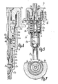
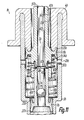
- a hand-operated dispensing device 1 has an essentially two-part pump housing 2 consisting of a cylinder housing 3 and a cylinder cover 4, which is placed on the outer further end of the cylinder housing 3 and, like the latter, lies in the pump axis 5 .
- a linearly displaceable piston unit 6 with two pump pistons 7, 8, two piston rods 9, 10 and two outlet valves 11, 12 is arranged in the pump axis 5, from which a piston rod 10 for actuating the pump with the release of an annular-gap ventilation channel 13 a through opening 14 of the cylinder cover 4 is led out of the pump housing 2.
- the output device 1 forms two separate thrust piston pumps 15, 16 which are essentially one behind the other in the direction of the pump axis 5, of which the pump 15 located in the direction of arrow 17 of the pump stroke and located at the inner end of the pump housing 2 for the pump shown in FIGS. 1 and 2
- the top position shown and the pump 16 located behind or adjacent to the cylinder cover 4 are designed for the top position according to FIGS. 3 and 4.
- the cylinder housing 3 forms a cylinder 18 for the pump 15 and a cylinder 19 for this directly afterwards for the pump 16, the cylinder 18 forming a piston track 20 for the pump piston 7 and the cylinder 19 forming a piston track 21 for the pump piston 8.
- the cylinder 18 delimits a pump chamber 22 with the associated pump piston 7, while the cylinder 19 delimits a pump chamber 23 with both pump pistons 7, 8 that expands into the cylinder 18 as the pump stroke increases.
- the inside width of the cylinder 19 is larger than that of the cylinder 18, the two cylinders or piston raceways 20, 21 merging into one another via an annular shoulder 24.
- the pump 15 has a suction channel 25 located in the pump axis 5, which is connected via a suction valve 27 designed as a check valve to the end of the pump chamber 22 opposite the pump piston 7 and is formed, for example, by an end connector of the cylinder housing 3 with a reduced diameter compared to the cylinder 18 , in which a not shown, at least approximately to the bottom of the riser pipe, for example a suction hose, which extends with the dispenser 1 to be emptied.
- the suction valve 27, the valve housing of which is formed in one piece with the cylinder housing 3, lies in the pump axis 5 at the transition between the cylinder 18 and the end connector.
- an intake duct 26 is provided which is formed by one or more openings in the cylinder jacket 29 of the cylinder 19 distributed around the axis 5 and which can be closed or opened by a slide valve 28 which is controlled by a slide depending on the stroke position of the pump piston 8.
- the openings of the suction channel 26 form connecting openings in the piston raceway 21 which, when the pump piston 8 is in the initial position, are close to its front end in the direction of arrow 17 of the pump stroke and are blocked by the pump piston 8 on the first section of the pump stroke by driving over to the pump chamber 23 so that the intake duct 26 is closed.
- the openings of the intake duct 26 open into the head space 31, which lies between the cylinder housing 3 protruding into the vessel and the wall of the vessel surrounding it, which also delimits the vessel opening, on the boundary of which the dispensing device 1 protrudes Flange edge of the cylinder cover 4 is fastened in a sealed manner, such that the aeration of the vessel can take place essentially exclusively via the pump housing 2.
- the head space 31 is filled by gravity with the medium to be discharged, from which the mouths of the suction channel 26 lying in the head space 31 are thus washed.
- the respective pump pistons 7 and 8 each have two annular piston lips 32, 33 and 34, 35 which project in opposite directions in the axial section, and which are widened towards their end edges, which are guided on the associated piston raceway 20, 21, at an acute angle in the shape of a truncated cone; the positive pressure in the pump chamber 22 thus increases the contact pressure of the front piston lip 32 of the pump piston 7, while the positive pressure in the pump chamber 23 automatically increases the contact pressure of the rear piston lip 33 of the pump piston 7 and the front piston lip 34 of the pump piston 8.
- the rear piston lip 35 of the pump piston 8 closes during the return stroke of the piston unit 6 by passing over the connecting openings 30, initially with respect to the space 36 of the pump housing 2 which is between the pump piston 8 and the cylinder cover 4 and which is used for loading or unloading.
- Vent channel 13 is open and therefore, after opening the intake channel 26 to the space 36 with the intake channel, constitutes part of the air balance connection between the interior of the vessel and the outside atmosphere.
- the pump piston 8 has closed the connection openings 30 with the rear piston lip 35, it still has to move back by a distance corresponding to the distance between the running edges of the piston lips 34, 35 until the suction channel 26 is opened by opening the connection openings 30 to the pump chamber 23.
- the rear piston lip 35 of the pump piston 8 engages in an annular groove of the pump housing 2 which is adapted to its cross section, in such a way that the inner end of the annularly shaped ventilation channel 13 is sealed.
- the inner end of an inner sleeve 38 of the cylinder cover 4 engaging in the outer open end of the cylinder housing 3 has for this purpose on its end face an annular projection 37 which surrounds the piston rod 10 and is adapted in cross section to the recessed cross section of the rear end face of the piston 8 , in such a way that it engages in the recessed end face in a sealing manner in the initial position of the piston unit 6 and defines the initial position of the piston unit 6 in the manner of a stop.
- the cylinder cover 4 has an outer sleeve 39 of approximately the same length, lying on the outer circumference of the cylinder housing 3, with the flange edge for fastening the dispensing device 1 to the vessel, such that the outer end of the cylinder housing 3 is completely sunk or embedded within the cylinder cover 4 lies.
- the two piston rods 9, 10, which can also be formed in one piece, delimit an inner channel 40 which extends from the front end face of the pump piston 7 to the outer end of the piston rod 10 or the piston unit 6 and lies in the pump axis 5.
- the piston rod 10 has a sleeve-shaped end sleeve 41, which projects beyond the front end face of the pump piston 8 and lies in the pump chamber 23, into which the end of the piston rod 9 remote from the pump piston 7 is inserted and held in a fixed position.
- the outlet valve 11 is provided in the piston rod 9 in the form of a hose valve, which can be designed, for example, according to DE-OS 29 02 624, to which reference is made for further details and features according to the invention.
- the valve body 42 is surrounded by an elastically expandable and self-resiliently resetting hose jacket 43, which forms the associated section of the inner channel 40 and the piston rod 9, namely in the exemplary embodiment shown is formed in one piece with the tubular piston rod 9. If the pressure in the pump chamber 22 reaches the opening pressure of the outlet valve 11, the hose jacket 43 is expanded in accordance with FIG.
- the outlet valve 12 which is located in the region of the front end face of the pump piston 8 and is provided for discharge from the pump chamber 23, has a hollow spherical cap-shaped valve body 44 lying in the valve axis or the pump axis 5, the closing surface of which is formed by its bulge outer side being an annular one Valve seat 45 is assigned, which is expediently in the same axis.
- the curved section of the valve body 44 can merge at its other end facing away from the valve seat 45 into a cylindrical sleeve-shaped section, the outer diameter of which is smaller than the surrounding inner diameter of the end sleeve 41 forming a valve housing, so that the valve body 44 on the inlet side of the valve seat 45 from an annular space 46 is surrounded.
- This annular space 46 which is closed on the outlet side by the valve body 45 resting on the valve seat 45, forms part of a side channel 47 which connects the inlet side of the outlet valve 12 to the pump chamber 23 and has openings in the jacket of the end sleeve 41 which are distributed around the pump axis 5 and which have the Connect the annular space 46 to the pump chamber 23.
- valve body 44 When the opening pressure of the outlet valve 12 in the pump chamber 23 is reached, the valve body 44 according to FIG. 4 is lifted from the valve seat 45 under elastic compression by the medium under pressure in the annular space 46, whereby the medium from the pump chamber 23 through the outlet valve 12 opened in this way can flow outward leading part of the inner channel 40. Due to the described design of the valve body 44, the latter has a spring characteristic such that its self-resilient restoring force initially becomes smaller with increasing opening travel, so that the discharge from the pump chamber 23 can take place with a single valve opening in one pass.
- the valve body 44 is formed in one piece with the piston rod 9 and forms its free end.
- valve body 44 is penetrated in the closed position with a radial distance within the valve seat 45 from the inner channel 40, for which purpose a cylindrical opening 48, for example cylindrical, is provided in the top of the valve body 5, which opens the inside of the piston rod 9 when the valve rod is in the closed position
- Exhaust valve 12 connects to the rest of the inner channel 40.
- the medium can thus pass through the outlet valve 12 unhindered, the medium flowing through the valve body 44 to the outside being able to increase the closing force of the outlet valve 12.
- the inner channel forms the common outlet channel 57 for both pumps 15, 16, the outlet opening 58 of which lies at the outer end of the piston unit.
- the suction valve 27 is designed as a check valve, which has a ball as the valve body and a valve seat 50 formed by an inner cone, which is narrowed towards the suction channel 25.
- stops for the valve body 49 are provided in the form of a cage 51 that is permeable to the medium, against which stops in the open position of the intake valve 27 according to FIG. 3.
- the interrupted annular cage 51 is designed in cross section so that at the end of the pump stroke it lies essentially completely within the recessed front end face of the pump piston 7 or engages in the front piston lip 32 such that it bears on the frustoconical inner surface thereof.
- a blocking member 52 is provided for the through opening 14 or the ventilation duct 13, which has a blocking cone 13 tapering in the shape of a truncated cone at an acute angle to the pump housing 2, which at the end of the pump stroke in accordance with FIGS Figures 2 and 4 so close to the outer ring boundary 54 of the through opening 14 of the cylinder cover 4 that the associated end of the ventilation channel 13 is sealed.
- the locking member 52 can sleeved on the outer end of the piston rod 10 and be part of a discharge head for actuating the dispensing device 1.
- the ring boundary 54 is appropriately rounded in cross section.
- the pump described works according to the following method: In the top position according to FIGS. 1 and 2, in which the dispensing device 1 is located on the top of the vessel to be emptied, for example with an approximately vertical pump axis 5, 27 medium is emitted when the piston unit 6 is returned by opening the suction valve sucked into the bottom region of the vessel into the pump chamber 22. In this case, the suction channel 26 is not flushed with medium, which is why the pump chamber 23 is also not filled with medium. In the subsequent pump stroke, the suction valve 27 closes and after reaching the opening pressure, the outlet valve 11 opens, so that the medium is discharged from the pump chamber 22 through the opening 48 and the inner channel 40 to the outside. In the head position according to FIGS.
- a negative pressure is built up in the pump chamber 23 during the return stroke, which after passing through the connection openings 30 through the Pump piston 8 leads to the suction of medium through the suction channel 26 into the pump chamber 23.
- the opening pressure of the outlet valve 12 is reached, the medium is discharged from the pump chamber 23 through the side channel 47, the outlet valve 12 and the inner channel 40.
- the valve body 49 of the intake valve 27 is in the open position by gravity, in which it is held by the cage 51.
- any medium or air present in the pump chamber 22 can thereby be pushed back into the vessel by the pump piston 7 through the suction channel 25, which is why in this case the suction valve 27 forms a ventilation channel for the pump 15 with the suction channel 25.
- the air can be equalized to the inside of the vessel in the manner described.
- the return stroke of the piston unit 6 takes place under the force of a return spring 55, which in the exemplary embodiment shown is arranged within the pump chamber 23 in the form of, for example, a helical compression spring surrounding the piston rod 9 and the end sleeve 41, which has one end in the front, recessed end face of the pump piston 8 and is supported with the other end on the annular shoulder 24, close to which the rear piston end of the pump piston 7 is in the starting position.
- a return spring 55 which in the exemplary embodiment shown is arranged within the pump chamber 23 in the form of, for example, a helical compression spring surrounding the piston rod 9 and the end sleeve 41, which has one end in the front, recessed end face of the pump piston 8 and is supported with the other end on the annular shoulder 24, close to which the rear piston end of the pump piston 7 is in the starting position.
- FIGS. 5 to 11 the same reference numerals are used for corresponding parts as in FIGS. 1 to 4, but in FIGS. 5 to 10 with the index "a" and in FIG. 11 with the index "b".
- the pump piston 8a of the pump 16a has only one piston lip, namely the front piston lip 34a.
- the connection openings 30a of the intake duct 26a at the beginning of the pump stroke are already released after passing over the sealing lip 34a to the space 36a of the pump housing 2a located behind the pump piston 8a.
- these connection openings 30a are closed towards the space 36a at the same time as they are released relative to the pump chamber 23a.
- valve body 44b of the outlet valve 12b is formed by a separate spring-plate-shaped component made of plastic, steel or the like, which in the closed position of the valve is axially self-resiliently clamped between an end face 56 and the valve seat 45b.
- the ring-shaped spring plate With its concave curvature side, the ring-shaped spring plate lies in a ring-shaped manner in the area of its outer circumference on the end face 56 provided as a support surface, while its contact with the valve seat 45b takes place on a diameter that is smaller by comparison, but larger than the opening 48b.
- valve body 44b is not curved in the closed position, but rather approximately flat and assumes a curved shape in the open position; the valve body 44b is axially biased between the annular end face 56 and the valve seat 45b.
- the valve body 44b On its convex curvature side, the valve body 44b is surrounded by the annular space 46b, which forms part of the side channel 47b, following the outer circumference of the valve seat 45b.
- the outside diameter of the valve body 44b is only slightly smaller than the inside diameter of the Annulus 46b, so that the valve body 44b maintains a precisely aligned position and can still perform its resilient opening movement unhindered.
Landscapes
- Engineering & Computer Science (AREA)
- Mechanical Engineering (AREA)
- General Engineering & Computer Science (AREA)
- Reciprocating Pumps (AREA)
- Details Of Reciprocating Pumps (AREA)
Applications Claiming Priority (2)
| Application Number | Priority Date | Filing Date | Title |
|---|---|---|---|
| DE3513575 | 1985-04-16 | ||
| DE19853513575 DE3513575A1 (de) | 1985-04-16 | 1985-04-16 | Handbetaetigte ausgabeeinrichtung fuer medien |
Publications (3)
| Publication Number | Publication Date |
|---|---|
| EP0199142A2 true EP0199142A2 (fr) | 1986-10-29 |
| EP0199142A3 EP0199142A3 (en) | 1987-10-07 |
| EP0199142B1 EP0199142B1 (fr) | 1990-07-04 |
Family
ID=6268149
Family Applications (1)
| Application Number | Title | Priority Date | Filing Date |
|---|---|---|---|
| EP19860104325 Expired - Lifetime EP0199142B1 (fr) | 1985-04-16 | 1986-03-27 | Dispositif de pulvérisation manuel |
Country Status (4)
| Country | Link |
|---|---|
| US (2) | US4823991A (fr) |
| EP (1) | EP0199142B1 (fr) |
| JP (1) | JPH0765566B2 (fr) |
| DE (2) | DE3513575A1 (fr) |
Cited By (1)
| Publication number | Priority date | Publication date | Assignee | Title |
|---|---|---|---|---|
| WO2018090068A1 (fr) * | 2016-11-21 | 2018-05-24 | Hans Georg Hagleitner | Élément de fermeture pouvant être inséré dans une ouverture de récipient, et récipient |
Families Citing this family (32)
| Publication number | Priority date | Publication date | Assignee | Title |
|---|---|---|---|---|
| DE3513575A1 (de) * | 1985-04-16 | 1986-10-16 | Ing. Erich Pfeiffer GmbH & Co KG, 7760 Radolfzell | Handbetaetigte ausgabeeinrichtung fuer medien |
| US4938392A (en) * | 1988-11-29 | 1990-07-03 | Su Cheng Yuan | Anti-leakage structure for a liquid atomizer |
| DE3929064A1 (de) * | 1989-06-29 | 1991-01-10 | Henkel Kgaa | Handbetaetigbarer fluessigkeitszerstaeuber zur abgabe dosierter mengen |
| DE4005528C2 (de) * | 1990-02-22 | 1998-01-15 | Pfeiffer Erich Gmbh & Co Kg | Austragvorrichtung für Medien |
| US5038965A (en) * | 1990-04-06 | 1991-08-13 | Spruhventile Gmbh | Pump dispenser for delivering a predetermined dosage regardless of method of actuation |
| DE4035290C2 (de) * | 1990-11-07 | 1994-02-24 | Kwasny Peter M | Ventil zur Entnahme von Flüssigkeit aus einem Behälter |
| US5147073A (en) * | 1991-02-11 | 1992-09-15 | Spruhventile Gmbh | Fluid pump dispenser for pharmaceutical use |
| US5388766A (en) * | 1993-09-22 | 1995-02-14 | The Procter & Gamble Company | High pressure atomization systems for high viscosity products |
| US5505343A (en) * | 1994-10-19 | 1996-04-09 | Knickerbocker; Michael G. | Manually actuated pump |
| US5503306A (en) * | 1994-10-19 | 1996-04-02 | Aptar Group, Inc. | Manually actuated pump |
| US6050457A (en) * | 1995-12-06 | 2000-04-18 | The Procter & Gamble Company | High pressure manually-actuated spray pump |
| US5850947A (en) * | 1996-07-15 | 1998-12-22 | Kim; Phillip S. | Invertible and multi-directional fluid delivery device |
| DE19807922A1 (de) | 1998-02-25 | 1999-08-26 | Pfeiffer Erich Gmbh & Co Kg | Spender für Medien |
| FR2781467B1 (fr) * | 1998-07-23 | 2000-10-06 | Valois Sa | Dispositif permettant le fonctionnement d'un distributeur de produit fluide en position droite et renversee |
| GB0208806D0 (en) * | 2002-04-17 | 2002-05-29 | Rieke Corp | Dispenser pumps |
| FR2848617B1 (fr) * | 2002-12-16 | 2006-03-17 | Oreal | Pompe et recipient ainsi equipe |
| US7325704B2 (en) * | 2003-09-10 | 2008-02-05 | Rieke Corporation | Inverted dispensing pump with vent baffle |
| US7389893B2 (en) * | 2003-09-10 | 2008-06-24 | Rieke Corporation | Inverted dispensing pump |
| ITMI20032162A1 (it) * | 2003-11-10 | 2005-05-11 | Microspray Delta Spa | Pompa invertibile per l'erogazione di liquidi atomizzati, |
| DE102004048248B3 (de) * | 2004-10-04 | 2006-02-09 | Seaquist Perfect Dispensing Gmbh | Adapter für eine handbetätigte Abgabevorrichtung für Flüssigkeitsbehälter |
| US7607592B1 (en) * | 2004-11-08 | 2009-10-27 | Kim Sang B | Accessories for water and beverage bottles |
| US9433960B2 (en) | 2008-09-01 | 2016-09-06 | Rieke Corporation | Liquid dosing devices |
| GB0815881D0 (en) | 2008-09-01 | 2008-10-08 | Rieke Corp | Liquid dosing devices |
| US8418889B2 (en) * | 2010-01-11 | 2013-04-16 | Rieke Corporation | Inverted dispenser pump with liquid inlet cup valve |
| GB201000601D0 (en) | 2010-01-14 | 2010-03-03 | Rieke Corp | Pump dispensers |
| GB201011143D0 (en) | 2010-07-01 | 2010-08-18 | Rieke Corp | Dispensers |
| GB201011144D0 (en) | 2010-07-01 | 2010-08-18 | Rieke Corp | Dispensers |
| DE102010048986A1 (de) * | 2010-10-20 | 2012-04-26 | Ursapharm Arzneimittel Gmbh | Dosierpumpe |
| GB201212042D0 (en) | 2012-07-05 | 2012-08-22 | Rieke Corp | Pump dispensers |
| USD920805S1 (en) | 2019-05-30 | 2021-06-01 | Berlin Packaging, Llc | Container with pump actuator |
| KR102197038B1 (ko) | 2019-07-19 | 2020-12-30 | 이은석 | 액체 잔량 소비를 위한 양방향 펌핑기 |
| US10752412B1 (en) | 2019-11-06 | 2020-08-25 | Berlin Packaging, Llc | Child resistant container with pump actuator |
Family Cites Families (23)
| Publication number | Priority date | Publication date | Assignee | Title |
|---|---|---|---|---|
| US208379A (en) * | 1878-09-24 | Improvement in vacuum-valves for stench-traps | ||
| US211168A (en) * | 1879-01-07 | Improvement in double-acting lift and force pumps | ||
| US1514724A (en) * | 1920-07-21 | 1924-11-11 | Reinhart W Pittman | Fire extinguisher |
| US1470469A (en) * | 1922-06-30 | 1923-10-09 | Nybakken Ingebret | Oil can |
| FR739221A (fr) * | 1932-06-29 | 1933-01-06 | Système de robinet d'eau | |
| US2362080A (en) * | 1942-10-26 | 1944-11-07 | Wilco Company | Dispensing device |
| US2765963A (en) * | 1952-10-10 | 1956-10-09 | Langguth Reinhold | Pump feed oil ejector can |
| US2792974A (en) * | 1955-07-05 | 1957-05-21 | La Vern N Smith | Pump type liquid dispenser |
| FR1242387A (fr) * | 1959-08-21 | 1960-09-30 | Pennel & Flipo Ets | Pompe à double effet, en particulier pour le gonflage d'articles pneumatiques |
| US3583430A (en) * | 1969-04-25 | 1971-06-08 | Erling P Toennesen | Annular flexible valve |
| US3760986A (en) * | 1970-08-19 | 1973-09-25 | Schuyler Dev Corp | Dispensing bottles with pump means for simultaneous dispensing |
| US3991914A (en) * | 1975-05-29 | 1976-11-16 | The Risdon Manufacturing Company | Easily assembled, leakproof liquid dispensing pump |
| JPS5620052Y2 (fr) * | 1975-07-21 | 1981-05-13 | ||
| JPS55380Y2 (fr) * | 1976-09-18 | 1980-01-08 | ||
| US4111367A (en) * | 1977-02-18 | 1978-09-05 | Ethyl Corporation | Finger operated spray pump |
| NL179791C (nl) * | 1977-05-12 | 1986-11-17 | Yoshino Kogyosho Co Ltd | Zowel rechtop als in omgekeerde stand te gebruiken verstuiver. |
| DE2943074C2 (de) * | 1978-06-07 | 1986-07-31 | Yoshino Kogyosho Co., Ltd., Tokio/Tokyo | In einen Behälterhals einsetzbarer Flüssigkeitszerstäuber |
| DE2902624C2 (de) * | 1979-01-24 | 1985-10-10 | Pfeiffer Zerstäuber Vertriebsgesellschaft mbH & Co KG, 7760 Radolfzell | Ausgabepumpe |
| US4249681A (en) * | 1979-06-11 | 1981-02-10 | The Dow Chemical Company | Leak-proof sprayer |
| JPS5720285U (fr) * | 1980-07-10 | 1982-02-02 | ||
| JPS5925095A (ja) * | 1982-07-31 | 1984-02-08 | Asahi Chem Ind Co Ltd | ポンプ装置 |
| DE3513575A1 (de) * | 1985-04-16 | 1986-10-16 | Ing. Erich Pfeiffer GmbH & Co KG, 7760 Radolfzell | Handbetaetigte ausgabeeinrichtung fuer medien |
| DE3517558A1 (de) * | 1985-05-15 | 1986-11-20 | Ing. Erich Pfeiffer GmbH & Co KG, 7760 Radolfzell | Handbetaetigte ausgabeeinrichtung fuer medien |
-
1985
- 1985-04-16 DE DE19853513575 patent/DE3513575A1/de not_active Withdrawn
-
1986
- 1986-03-27 EP EP19860104325 patent/EP0199142B1/fr not_active Expired - Lifetime
- 1986-03-27 DE DE8686104325T patent/DE3672375D1/de not_active Expired - Lifetime
- 1986-04-10 US US06/850,506 patent/US4823991A/en not_active Expired - Lifetime
- 1986-04-15 JP JP8523486A patent/JPH0765566B2/ja not_active Expired - Fee Related
-
1989
- 1989-01-26 US US07/303,285 patent/US5115980A/en not_active Expired - Fee Related
Cited By (7)
| Publication number | Priority date | Publication date | Assignee | Title |
|---|---|---|---|---|
| WO2018090068A1 (fr) * | 2016-11-21 | 2018-05-24 | Hans Georg Hagleitner | Élément de fermeture pouvant être inséré dans une ouverture de récipient, et récipient |
| AT519376A1 (de) * | 2016-11-21 | 2018-06-15 | Georg Hagleitner Hans | In eine Behälteröffnung einsetzbares Verschlusselement |
| AT519376B1 (de) * | 2016-11-21 | 2018-08-15 | Georg Hagleitner Hans | In eine Behälteröffnung einsetzbares Verschlusselement |
| CN109982941A (zh) * | 2016-11-21 | 2019-07-05 | 汉斯·格奥尔格·哈格莱特纳 | 能够插入容器开口中的封闭元件 |
| EA035639B1 (ru) * | 2016-11-21 | 2020-07-20 | Ханс Георг Хагляйтнер | Вставляемый в отверстие емкости запорный элемент и емкость |
| CN109982941B (zh) * | 2016-11-21 | 2020-11-27 | 汉斯·格奥尔格·哈格莱特纳 | 能够插入容器开口中的封闭元件 |
| US10988367B2 (en) | 2016-11-21 | 2021-04-27 | Hans Georg Hagleitner | Container and closure element insertable into a container opening |
Also Published As
| Publication number | Publication date |
|---|---|
| DE3672375D1 (de) | 1990-08-09 |
| US4823991A (en) | 1989-04-25 |
| US5115980A (en) | 1992-05-26 |
| JPS61241467A (ja) | 1986-10-27 |
| DE3513575A1 (de) | 1986-10-16 |
| EP0199142A3 (en) | 1987-10-07 |
| EP0199142B1 (fr) | 1990-07-04 |
| JPH0765566B2 (ja) | 1995-07-19 |
Similar Documents
| Publication | Publication Date | Title |
|---|---|---|
| EP0199142B1 (fr) | Dispositif de pulvérisation manuel | |
| EP0201701B1 (fr) | Dispositif de pulvérisation manuel | |
| DE2943074C2 (de) | In einen Behälterhals einsetzbarer Flüssigkeitszerstäuber | |
| EP1260159B1 (fr) | Amortisseur, en particulier pour mobilier | |
| DE69028100T2 (de) | Flüssigkeitszerstäuber | |
| DE10049898C2 (de) | Abgabevorrichtung für Fluide | |
| DE2902624A1 (de) | Zerstaeuberpumpe | |
| EP0199143A1 (fr) | Pompe à piston coulissant pour délivrer des substances fluides | |
| DE3425478A1 (de) | Fluessigkeitszerstaeuber | |
| DE2001921A1 (de) | Hin- und herbewegte Fluessigkeitsabgabepumpe | |
| DE19723133A1 (de) | Austragvorrichtung für Medien | |
| DE1500597B2 (de) | Tauchrohrzerstäuber | |
| EP0217013B1 (fr) | Ressort à gaz réglable en longueur | |
| DE1282388B (de) | Vorrichtung zur Trennung von Medien unterschiedlicher Viskositaet | |
| DE2241927A1 (de) | Zerstaeuber | |
| EP0289854B1 (fr) | Distributeur de fluides | |
| DE19727356B4 (de) | Spender für Medien | |
| DE2907100C2 (fr) | ||
| DE3834091C2 (fr) | ||
| EP0289856B1 (fr) | Distributeur de fluide | |
| EP0286925B1 (fr) | Dispositif pour la distribution de liquides | |
| DE102021100029A1 (de) | Arretiersystem | |
| DE2705071A1 (de) | Von hand betaetigbare spruehvorrichtung mit automatischer behaelterentlueftung | |
| DE9204264U1 (de) | Längenverstellbare Gasfeder | |
| DE1941678A1 (de) | Ventil eines Druckverstaerkers |
Legal Events
| Date | Code | Title | Description |
|---|---|---|---|
| PUAI | Public reference made under article 153(3) epc to a published international application that has entered the european phase |
Free format text: ORIGINAL CODE: 0009012 |
|
| AK | Designated contracting states |
Kind code of ref document: A2 Designated state(s): CH DE FR GB IT LI |
|
| PUAL | Search report despatched |
Free format text: ORIGINAL CODE: 0009013 |
|
| AK | Designated contracting states |
Kind code of ref document: A3 Designated state(s): CH DE FR GB IT LI |
|
| RHK1 | Main classification (correction) |
Ipc: B65D 47/34 |
|
| 17P | Request for examination filed |
Effective date: 19880310 |
|
| 17Q | First examination report despatched |
Effective date: 19890309 |
|
| GRAA | (expected) grant |
Free format text: ORIGINAL CODE: 0009210 |
|
| AK | Designated contracting states |
Kind code of ref document: B1 Designated state(s): CH DE FR GB IT LI |
|
| REF | Corresponds to: |
Ref document number: 3672375 Country of ref document: DE Date of ref document: 19900809 |
|
| ET | Fr: translation filed | ||
| GBT | Gb: translation of ep patent filed (gb section 77(6)(a)/1977) | ||
| ITF | It: translation for a ep patent filed | ||
| ITTA | It: last paid annual fee | ||
| PLBE | No opposition filed within time limit |
Free format text: ORIGINAL CODE: 0009261 |
|
| STAA | Information on the status of an ep patent application or granted ep patent |
Free format text: STATUS: NO OPPOSITION FILED WITHIN TIME LIMIT |
|
| 26N | No opposition filed | ||
| PGFP | Annual fee paid to national office [announced via postgrant information from national office to epo] |
Ref country code: GB Payment date: 19930310 Year of fee payment: 8 |
|
| PGFP | Annual fee paid to national office [announced via postgrant information from national office to epo] |
Ref country code: FR Payment date: 19930315 Year of fee payment: 8 |
|
| PGFP | Annual fee paid to national office [announced via postgrant information from national office to epo] |
Ref country code: CH Payment date: 19930419 Year of fee payment: 8 |
|
| PGFP | Annual fee paid to national office [announced via postgrant information from national office to epo] |
Ref country code: DE Payment date: 19930519 Year of fee payment: 8 |
|
| PG25 | Lapsed in a contracting state [announced via postgrant information from national office to epo] |
Ref country code: GB Effective date: 19940327 |
|
| PG25 | Lapsed in a contracting state [announced via postgrant information from national office to epo] |
Ref country code: LI Effective date: 19940331 Ref country code: CH Effective date: 19940331 |
|
| GBPC | Gb: european patent ceased through non-payment of renewal fee |
Effective date: 19940327 |
|
| PG25 | Lapsed in a contracting state [announced via postgrant information from national office to epo] |
Ref country code: FR Effective date: 19941130 |
|
| REG | Reference to a national code |
Ref country code: CH Ref legal event code: PL |
|
| PG25 | Lapsed in a contracting state [announced via postgrant information from national office to epo] |
Ref country code: DE Effective date: 19941201 |
|
| REG | Reference to a national code |
Ref country code: FR Ref legal event code: ST |
|
| PG25 | Lapsed in a contracting state [announced via postgrant information from national office to epo] |
Ref country code: IT Free format text: LAPSE BECAUSE OF NON-PAYMENT OF DUE FEES;WARNING: LAPSES OF ITALIAN PATENTS WITH EFFECTIVE DATE BEFORE 2007 MAY HAVE OCCURRED AT ANY TIME BEFORE 2007. THE CORRECT EFFECTIVE DATE MAY BE DIFFERENT FROM THE ONE RECORDED. Effective date: 20050327 |