EP0199160B1 - Méthode de génération d'un arc circulaire ou elliptique - Google Patents
Méthode de génération d'un arc circulaire ou elliptique Download PDFInfo
- Publication number
- EP0199160B1 EP0199160B1 EP86104603A EP86104603A EP0199160B1 EP 0199160 B1 EP0199160 B1 EP 0199160B1 EP 86104603 A EP86104603 A EP 86104603A EP 86104603 A EP86104603 A EP 86104603A EP 0199160 B1 EP0199160 B1 EP 0199160B1
- Authority
- EP
- European Patent Office
- Prior art keywords
- circle
- points
- point
- painting
- circular
- Prior art date
- Legal status (The legal status is an assumption and is not a legal conclusion. Google has not performed a legal analysis and makes no representation as to the accuracy of the status listed.)
- Expired
Links
Images




Classifications
-
- G—PHYSICS
- G06—COMPUTING OR CALCULATING; COUNTING
- G06K—GRAPHICAL DATA READING; PRESENTATION OF DATA; RECORD CARRIERS; HANDLING RECORD CARRIERS
- G06K15/00—Arrangements for producing a permanent visual presentation of the output data, e.g. computer output printers
- G06K15/22—Arrangements for producing a permanent visual presentation of the output data, e.g. computer output printers using plotters
-
- G—PHYSICS
- G06—COMPUTING OR CALCULATING; COUNTING
- G06K—GRAPHICAL DATA READING; PRESENTATION OF DATA; RECORD CARRIERS; HANDLING RECORD CARRIERS
- G06K15/00—Arrangements for producing a permanent visual presentation of the output data, e.g. computer output printers
-
- G—PHYSICS
- G06—COMPUTING OR CALCULATING; COUNTING
- G06T—IMAGE DATA PROCESSING OR GENERATION, IN GENERAL
- G06T11/00—Two-dimensional [2D] image generation
- G06T11/20—Drawing from basic elements
- G06T11/23—Drawing from basic elements using straight lines or curves
-
- G—PHYSICS
- G09—EDUCATION; CRYPTOGRAPHY; DISPLAY; ADVERTISING; SEALS
- G09G—ARRANGEMENTS OR CIRCUITS FOR CONTROL OF INDICATING DEVICES USING STATIC MEANS TO PRESENT VARIABLE INFORMATION
- G09G5/00—Control arrangements or circuits for visual indicators common to cathode-ray tube indicators and other visual indicators
- G09G5/20—Function-generator circuits, e.g. circle generators line or curve smoothing circuits
-
- G—PHYSICS
- G06—COMPUTING OR CALCULATING; COUNTING
- G06K—GRAPHICAL DATA READING; PRESENTATION OF DATA; RECORD CARRIERS; HANDLING RECORD CARRIERS
- G06K2215/00—Arrangements for producing a permanent visual presentation of the output data
- G06K2215/0002—Handling the output data
- G06K2215/004—Generic data transformation
- G06K2215/0042—Rasterisation
Definitions
- the present invention relates to a method for generating a circular or elliptic arc on a digital display, such as a cathode ray tube display, a digital plotter, or a matrix printer, especially adapted for use in painting tee whole or part of a circle or ellipse.
- a digital display such as a cathode ray tube display, a digital plotter, or a matrix printer
- a painted pattern has generally been displayed by drawing the boundary of a pattern to be painted, discriminating the area inside of the boundary, which is to be painted, from the area outside thereof, which is not to be painted, in accordance with the data read out from a display memory, and painting the area inside of the boundary.
- An example of such a method is disclosed in Jap. Pat. Unexam. Pub. Appln. No. 142585/81. This method is time-consuming since it requires to read out data from the display memory one by one. Further, the painting of a-pattern by such a method, which largely depends on the contents already drawn on a display screen, may often interfere with another pattern.
- Another known method for displaying a painted pattern is a scan conversion method.
- the method is described, for example, in "Principles of Interactive Computer Graphics," W. M. Newman, et. al., McGrow-Hill, 2nd Edition, 1979, pp.232 - 243.
- this method all the intersections between the pattern to be painted and the scan lines constituting a display screen are obtained, and the spaces between the odd-even paired intersections are painted.
- Fig. 2 illustrates a typical example thereof.
- This method effectively utilizes the geometrical nature of the pattern to be painted to enable the painting to be executed independently of the data stored in a display memory, resulting in its improved processing speed. It is the key to the improvement of the scan conversion method to improve the efficiency in the calculation of intersections while retaining its high accuracy.
- the present invention is directed to the scan conversion method, and introduces a new concept in generating a circular or elliptic arc in order to solve the problems of accuracy encountered in the past.
- One of the methods is to move a point incrementally from a starting point to a terminating point in order to obtain a desired line segment.
- the incremental movement of a point means, for example, a movement thereof from one picture element (hereinafter referred to as a pel) to any one of the pels at the angular positions of 0, 90, 180, and 270 degrees among those neighbouring thereto.
- the combination is called "4-connected pels.”
- the incremental movement may also be made from one pel to any one of those at the angular positions of 0, 45, 90, ..., and 315 degrees.
- the combination is called "8-connected pels.” In selecting the next pel to which the movement is to be made, a test is performed to select two or three neighbouring pels as candidates.
- a point P k ( x k , y k ) located on the circumference of a circle with a radius r has been obtained.
- the point moved by ⁇ ⁇ from the point p k counterclockwise on the circle p k+1 ( x k+1 , y k+1 ) is expressed by the following formulae: Assuming that ⁇ ⁇ in the above formulae is a minute angle, cos ⁇ ⁇ ⁇ 1 and sin ⁇ ⁇ ⁇ ⁇ ⁇ .
- the present invention intends to prevent a plurality of points to be generated at the intersection between one scan line and the curve concerned by modifying the recurrence formulae of the DDA method.
- the linear painting with the scan conversion method is performed in the x - axis direction, which is orthogonal to the y - axis direction.
- the minute vector ( - ey k , ex k ) is orthogonal to the vector ( x k , y k ). Therefore, the series of points obtained from the above formulae (3) and (4) will be diverted.
- the formulae (5) and (6) eliminate such a diversion. Namely, the formulae (5) and (6) may be expressed by a matrix as follows: In the above formula (11), since is 1, it is apparent that the series of points generated from the above formula (11) generate a true circle. This is described in "On Linear Difference Curves," D. Cohen, Dept. Eng. Appln. Math., Harvard Univ., 1969.
- the above formulae may be expressed by a matrix as follows: Of course, the above formula (12), wherein generates a true circle.
- the formulae (6) and (7) can generate a true circle by plotting a single point at each intersection with a scan line.
- the formulae (6) and (7) are those for plotting a circle counterclockwise and the formulae (8) and (9) are those for plotting a circle clockwise.
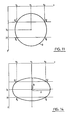
- the pels on the scan line passing through the center ( x c , y c ) of a circle are painted from a point p s through a point p e , as shown in Fig. 9, and thereafter the pels on the adjacent scan lines upwardly and downwardly are sequentially painted, as shown in Fig. 10. More particularly, as shown in Fig. 11, after the point p s on a desired circle is determined, the points p e , p s ', and p e 'are obtained by employing the symmetry of a circle. Then, the pels between the points p s and p e as well as the pels between the points p s ' and p e ' are painted.
- the symbols to be used in the description of this embodiment are shown in Fig. 11.
- Fig. 8 shows generally a personal computer system employed to implement this embodiment of the invention.
- the system may be IBM 5550 manufactured by IBM Japan, Ltd.
- a CPU 2 a keyboard 3, a floppy disk drive 4, a CRT display 5, a main storage 6, a refresh buffer 7, and so on are connected to a data bus 1.
- a keyboard interface 8, a floppy disk controller 9, and a CRT display controller 10 are provided as interfaces between the data bus 1 and each of the keyboard 3, floppy disk drive 4, and CRT display 5.
- an address bus, a control bus , ROS, and so on are not shown.
- the CRT display 5 may be of the 15 inch - monochrome type, which is capable of displaying 1024 x 768 points with spots of approximately 0.22 mm.
- the refresh buffer 7 has a capacity which is able to support the all point addressable graphic mode.
- the refresh buffer 7 can be addressed by the CPU 2 and the CRT display controller 10, and the graphic data can be written into or read from the refresh buffer 7 by CPU addresses.
- the CRT display controller 10 accesses the refresh buffer 7 according to the vertical-synchronizing signals and the horizontal-synchronizing signals for the CRT display 5, and displays the contents on the CRT display 5.
- the method of the present invention may be implemented, for example, as a package disk for an application program. When the package disk is loaded in a floppy disk drive 4 under the control of a disk operating system, the program is transferred to the main storage 6 and then executed. The method of this embodiment is shown in detail in Fig. 1.
- a point p s on a desired circle O is obtained by first obtaining a point ( x , y ) on a circle O' with a radius r and an original point ( 0 , 0 ) at its center by the modified DDA method, and then translating the point.
- the points p e ' p s ', and p e ' can be further obtained based on the point p s in the same manner.
- the keyboard 3 is used to input the data of the center. ( x c , y c ) and the radius r of the circle to be painted. As the result, the data x c , y c , and r are transferred to the main storage 6.
- the point ( x , y ) on the circle O' and the counter C are initialized to ( r , 0 ) and 0, respectively. Since the point ( r , 0 ) on the x - axis is used as the starting point for incrementation, the radius data can be employed directly as the initialization data. If a point on the circle O' which is not located on the x or y - axis is used as such a starting point, the calculation of square roots are required to obtain the initialization data, thereby rendering the method complicated.
- the data y c , x c - r , and r + x c for the intersections p s and p e between the scan line passing through the center ( x c , y c ) and the circle O are substituted to y y , x s , and x e , respectively.
- the painting data are written into the locations of the refresh buffer 7 corresponding to the pels between the point ( x s , y c ) through the point ( x e , y c ).
- the painting of one scan line shown in Fig. 9 has been completed. Thereafter, the scan conversions will be continued for the adjacent scan lines upwardly or downwardly.
- step 15 the counter C and the value of the y coordinate y of the point on the circle O' are respectively incremented by one, and the value of x coordinate x of the point on the circle O' is substituted by x - y / x. Then, in the step 16, y y , x s , and x e are substituted by y + y c , x c - [x], and [x] + x c , respectively.
- the [x] indicates the integer part of x. It is apparent that the above operation has been made to obtain the intersections p s and p e between the scan line and the circle O after the incrementation by one.
- the painting for the scan line after the incrementation is performed. Namely, the painting data are written into the locations of the refresh buffer 7 corresponding to the pels between the point p s ( x s , y y ) through the point p e ( x e , y y ).
- the painting is made for the scan line between the point p s ' and the point p e '. Namely, since the line segment p s p e is symmetrical with the line segment p s 'p e ' about the x - axis, y y is substituted by y c - y (step 18). Then, in the step 19, the painting is made in the same manner as in the step 17.
- steps 15 through 19 are repeated until the counter C becomes equal to r - 1, in the step 20.
- steps 21 and 22 are executed, and the operation is completed.
- the painting data are written into the locations of the refresh buffer 7 corresponding to the points ( r + y c , x c ) and ( y c - r , x c ), respectively.
- the points along the circle O as shown by small circles in Fig. 12 are plotted, and the spaces between each pair of the plotted points on the same scan line are painted.
- the painted circle is displayed on the CRT display 5.
- FIG. 13 the steps that are similar to those in Fig. 1 are identified by the numerals added with 100, and only the portions differing from the preceding embodiment will be explained below.
- the keyboard 3 is used to input the data of the center ( x c , y c ) and the major and minor axes a and b.
- y y , x s , and x e are substituted by y c , x c - a and a + x c , respectively.
- x c - [a* x / b] and [a* x / b] + x c are substituted to x s and x e , respectively.
- the painting data are written into the locations of the refresh buffer 7 corresponding to the points ( b + y c , x c ) and ( y c - b , x c ).
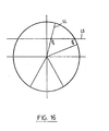
- the present invention could also be used for painting a pie chart as shown in Fig. 16.
- a table is made as to the odd - even paired intersections on the scan lines which are to be painted therebetween, and based on the table, the painting data are written into the refresh buffer 7.
- the intersection between the scan line LS and the circle O may be obtained by the method of the present invention and the intersection between the straight line LL and the scan line LS may be obtained by any known method such as the Presenham's method, and the data are stored in a table. It is also possible to obtain a pie chart made from an ellipse in the same manner.
- the present invention enables to generate a highly precise circle or ellipse, and is adapted for use in the scan conversion method since an intersection between a scan line and a curve concerned is defined as a single point but not as a plurality of points. Further, the present invention enables to generate a circle or an ellipse in a short period of time without necessitating the calculation of square roots and trigonometric functions.
Landscapes
- Engineering & Computer Science (AREA)
- Physics & Mathematics (AREA)
- General Physics & Mathematics (AREA)
- Theoretical Computer Science (AREA)
- General Engineering & Computer Science (AREA)
- Computer Hardware Design (AREA)
- Image Generation (AREA)
- Digital Computer Display Output (AREA)
- Controls And Circuits For Display Device (AREA)
Claims (3)
- Procédé de commande d'un dispositif de visualisation numérique pour produire la visualisation d'un arc circulaire ou elliptique comprenant les étapes consistant à :
produire une suite de points (xk, yk) dans laquelle k = 0, 1, 2, ... et xk ≠ 0, faire partir l'origine d'un point de début donné (x₀, y₀) en conformité avec les formules de récurrence suivantes :
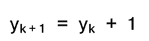

ou


transformer les coordonnées de ladite suite de points pour produire un arc circulaire ou elliptique, sur ledit dispositif de visualisation numérique, dont un centre est placé sur une position de coordonnées souhaitée dudit dispositif de visualisation. - Procédé selon la revendication 1, comprenant de plus les étapes consistant à :
mémoriser les données concernant ledit arc circulaire ou elliptique dans une table, et
colorier la totalité ou la partie d'un cercle ou d'une ellipse par un procédé de conversion par balayage en réponse aux données mémorisées dans ladite table. - Procédé selon la revendication 1, dans lequel ledit point de début (x₀, y₀) est sur l'axe x.
Applications Claiming Priority (2)
| Application Number | Priority Date | Filing Date | Title |
|---|---|---|---|
| JP89088/85 | 1985-04-26 | ||
| JP60089088A JPS61249088A (ja) | 1985-04-26 | 1985-04-26 | 図形塗りつぶし方法 |
Publications (3)
| Publication Number | Publication Date |
|---|---|
| EP0199160A2 EP0199160A2 (fr) | 1986-10-29 |
| EP0199160A3 EP0199160A3 (en) | 1990-06-27 |
| EP0199160B1 true EP0199160B1 (fr) | 1992-11-11 |
Family
ID=13961116
Family Applications (1)
| Application Number | Title | Priority Date | Filing Date |
|---|---|---|---|
| EP86104603A Expired EP0199160B1 (fr) | 1985-04-26 | 1986-04-04 | Méthode de génération d'un arc circulaire ou elliptique |
Country Status (5)
| Country | Link |
|---|---|
| US (1) | US5146551A (fr) |
| EP (1) | EP0199160B1 (fr) |
| JP (1) | JPS61249088A (fr) |
| CA (1) | CA1247246A (fr) |
| DE (1) | DE3687077T2 (fr) |
Families Citing this family (7)
| Publication number | Priority date | Publication date | Assignee | Title |
|---|---|---|---|---|
| GB9009127D0 (en) * | 1990-04-24 | 1990-06-20 | Rediffusion Simulation Ltd | Image generator |
| US5420970A (en) * | 1991-03-13 | 1995-05-30 | Martin Marietta Corporation | Method for determining computer image generation display pixels occupied by a circular feature |
| GB9312447D0 (en) * | 1992-10-28 | 1993-07-28 | Int Technical Illustration Co | Method of tracing a drawing and apparatus for embodying the method |
| JP3210141B2 (ja) * | 1993-06-24 | 2001-09-17 | 松下電器産業株式会社 | 直線描画装置 |
| WO2003071452A2 (fr) * | 2002-02-15 | 2003-08-28 | Computer Associates Think, Inc. | Systeme et procede permettant de specifier des parametres elliptiques |
| JP2005031369A (ja) * | 2003-07-11 | 2005-02-03 | Toshiba Corp | 映像表示装置及び映像表示方法 |
| CN102646281B (zh) * | 2011-02-16 | 2015-02-11 | 富士通株式会社 | 用于对椭圆弧进行栅格化的方法和系统 |
Family Cites Families (10)
| Publication number | Priority date | Publication date | Assignee | Title |
|---|---|---|---|---|
| US4283765A (en) * | 1978-04-14 | 1981-08-11 | Tektronix, Inc. | Graphics matrix multiplier |
| US4631750A (en) * | 1980-04-11 | 1986-12-23 | Ampex Corporation | Method and system for spacially transforming images |
| JPS578584A (en) * | 1980-06-18 | 1982-01-16 | Nippon Electric Co | Video controller |
| AU542593B2 (en) * | 1981-01-21 | 1985-02-28 | Tokyo Shibaura Denki Kabushiki Kaisha | Straight line co-ordinates generator |
| JPS59137942A (ja) * | 1983-01-28 | 1984-08-08 | Hitachi Ltd | 画像位置合わせ方式 |
| JPS59206884A (ja) * | 1983-05-10 | 1984-11-22 | カシオ計算機株式会社 | 円または楕円の塗りつぶし方式 |
| US4692887A (en) * | 1983-05-10 | 1987-09-08 | Casio Computer Co., Ltd. | Circle and circular arc generator |
| US4602346A (en) * | 1983-05-19 | 1986-07-22 | Matsushita Electric Industrial Co., Ltd. | Method and apparatus for processing image data using sum and subtract operations |
| US4593406A (en) * | 1984-01-16 | 1986-06-03 | The United States Of America As Represented By The United States Department Of Energy | Automatic image acquisition processor and method |
| GB8415602D0 (en) * | 1984-06-19 | 1984-07-25 | Secr Defence | Raster image manipulator |
-
1985
- 1985-04-26 JP JP60089088A patent/JPS61249088A/ja active Granted
-
1986
- 1986-02-05 CA CA000501113A patent/CA1247246A/fr not_active Expired
- 1986-04-04 EP EP86104603A patent/EP0199160B1/fr not_active Expired
- 1986-04-04 DE DE8686104603T patent/DE3687077T2/de not_active Expired - Fee Related
- 1986-04-18 US US06/853,572 patent/US5146551A/en not_active Expired - Fee Related
Also Published As
| Publication number | Publication date |
|---|---|
| EP0199160A2 (fr) | 1986-10-29 |
| JPH0366675B2 (fr) | 1991-10-18 |
| US5146551A (en) | 1992-09-08 |
| DE3687077T2 (de) | 1993-04-15 |
| JPS61249088A (ja) | 1986-11-06 |
| CA1247246A (fr) | 1988-12-20 |
| DE3687077D1 (de) | 1992-12-17 |
| EP0199160A3 (en) | 1990-06-27 |
Similar Documents
| Publication | Publication Date | Title |
|---|---|---|
| EP0360155B1 (fr) | Méthode et appareil de transformation d'image | |
| EP0242598B1 (fr) | Sous-système de détection d'un style sur un écran de visualisation avec une erreur de parallaxe minimum | |
| EP0356103A2 (fr) | Procédé et processeur pour conversion de balayage | |
| JPH0126072B2 (fr) | ||
| US4625202A (en) | Apparatus and method for generating multiple cursors in a raster scan display system | |
| EP0199160B1 (fr) | Méthode de génération d'un arc circulaire ou elliptique | |
| EP0344686B1 (fr) | Procédé et processeur de découpage | |
| EP0301253B1 (fr) | Génération de lignes dans un système d'affichage | |
| EP0305034B1 (fr) | Méthode et appareil pour le calcul incrémentiel d'une fonction linéaire | |
| JPH0677265B2 (ja) | 曲線発生装置 | |
| JPH03210680A (ja) | 曲線発生装置 | |
| JPH03119387A (ja) | デジタル活字面の輪郭を形成する方法およびその装置 | |
| US3437869A (en) | Display apparatus | |
| US5297244A (en) | Method and system for double error antialiasing in a computer display system | |
| US5077681A (en) | System for source image transformation | |
| JPS5843747B2 (ja) | エンスイキヨクセンハツセイソウチ | |
| JP2630843B2 (ja) | 直線描画方法及び装置 | |
| US5305431A (en) | Method and system for rendering polygons on a raster display | |
| JP2729437B2 (ja) | 楕円描画装置 | |
| JPH0827842B2 (ja) | 走査型デイスプレイ装置における多角形頂点デ−タ追尾装置 | |
| JPS63221493A (ja) | ビツトマツプの直線描画方式 | |
| Badler | Scan conversion | |
| JPS61286895A (ja) | グラフイツク装置における直線描画方式 | |
| Myers | Fundamental concepts of microcomputer graphics | |
| JPS63271394A (ja) | カ−ソル制御装置 |
Legal Events
| Date | Code | Title | Description |
|---|---|---|---|
| PUAI | Public reference made under article 153(3) epc to a published international application that has entered the european phase |
Free format text: ORIGINAL CODE: 0009012 |
|
| AK | Designated contracting states |
Kind code of ref document: A2 Designated state(s): DE FR GB IT |
|
| 17P | Request for examination filed |
Effective date: 19870224 |
|
| PUAL | Search report despatched |
Free format text: ORIGINAL CODE: 0009013 |
|
| AK | Designated contracting states |
Kind code of ref document: A3 Designated state(s): DE FR GB IT |
|
| 17Q | First examination report despatched |
Effective date: 19920117 |
|
| GRAA | (expected) grant |
Free format text: ORIGINAL CODE: 0009210 |
|
| AK | Designated contracting states |
Kind code of ref document: B1 Designated state(s): DE FR GB IT |
|
| PG25 | Lapsed in a contracting state [announced via postgrant information from national office to epo] |
Ref country code: IT Free format text: LAPSE BECAUSE OF FAILURE TO SUBMIT A TRANSLATION OF THE DESCRIPTION OR TO PAY THE FEE WITHIN THE PRE;WARNING: LAPSES OF ITALIAN PATENTS WITH EFFECTIVE DATE BEFORE 2007 MAY HAVE OCCURRED AT ANY TIME BEFORE 2007. THE CORRECT EFFECTIVE DATE MAY BE DIFFERENT FROM THE ONE RECORDED.SCRIBED TIME-LIMIT Effective date: 19921111 |
|
| REF | Corresponds to: |
Ref document number: 3687077 Country of ref document: DE Date of ref document: 19921217 |
|
| ET | Fr: translation filed | ||
| PLBE | No opposition filed within time limit |
Free format text: ORIGINAL CODE: 0009261 |
|
| STAA | Information on the status of an ep patent application or granted ep patent |
Free format text: STATUS: NO OPPOSITION FILED WITHIN TIME LIMIT |
|
| 26N | No opposition filed | ||
| PGFP | Annual fee paid to national office [announced via postgrant information from national office to epo] |
Ref country code: GB Payment date: 19950324 Year of fee payment: 10 |
|
| PGFP | Annual fee paid to national office [announced via postgrant information from national office to epo] |
Ref country code: FR Payment date: 19950328 Year of fee payment: 10 |
|
| PGFP | Annual fee paid to national office [announced via postgrant information from national office to epo] |
Ref country code: DE Payment date: 19950428 Year of fee payment: 10 |
|
| PG25 | Lapsed in a contracting state [announced via postgrant information from national office to epo] |
Ref country code: GB Effective date: 19960404 |
|
| GBPC | Gb: european patent ceased through non-payment of renewal fee |
Effective date: 19960404 |
|
| PG25 | Lapsed in a contracting state [announced via postgrant information from national office to epo] |
Ref country code: FR Effective date: 19961227 |
|
| PG25 | Lapsed in a contracting state [announced via postgrant information from national office to epo] |
Ref country code: DE Effective date: 19970101 |
|
| REG | Reference to a national code |
Ref country code: FR Ref legal event code: ST |