EP0199185B1 - Dispositif d'impression - Google Patents
Dispositif d'impression Download PDFInfo
- Publication number
- EP0199185B1 EP0199185B1 EP86104848A EP86104848A EP0199185B1 EP 0199185 B1 EP0199185 B1 EP 0199185B1 EP 86104848 A EP86104848 A EP 86104848A EP 86104848 A EP86104848 A EP 86104848A EP 0199185 B1 EP0199185 B1 EP 0199185B1
- Authority
- EP
- European Patent Office
- Prior art keywords
- printing
- time
- hammer
- time data
- energy
- Prior art date
- Legal status (The legal status is an assumption and is not a legal conclusion. Google has not performed a legal analysis and makes no representation as to the accuracy of the status listed.)
- Expired
Links
- 230000005764 inhibitory process Effects 0.000 description 24
- 238000000034 method Methods 0.000 description 6
- 238000010586 diagram Methods 0.000 description 2
- 238000012545 processing Methods 0.000 description 2
- 239000002699 waste material Substances 0.000 description 2
- 230000006870 function Effects 0.000 description 1
- 230000002401 inhibitory effect Effects 0.000 description 1
Images


Classifications
-
- B—PERFORMING OPERATIONS; TRANSPORTING
- B41—PRINTING; LINING MACHINES; TYPEWRITERS; STAMPS
- B41J—TYPEWRITERS; SELECTIVE PRINTING MECHANISMS, i.e. MECHANISMS PRINTING OTHERWISE THAN FROM A FORME; CORRECTION OF TYPOGRAPHICAL ERRORS
- B41J9/00—Hammer-impression mechanisms
- B41J9/44—Control for hammer-impression mechanisms
- B41J9/48—Control for hammer-impression mechanisms for deciding or adjusting hammer-drive energy
-
- B—PERFORMING OPERATIONS; TRANSPORTING
- B41—PRINTING; LINING MACHINES; TYPEWRITERS; STAMPS
- B41J—TYPEWRITERS; SELECTIVE PRINTING MECHANISMS, i.e. MECHANISMS PRINTING OTHERWISE THAN FROM A FORME; CORRECTION OF TYPOGRAPHICAL ERRORS
- B41J1/00—Typewriters or selective printing mechanisms characterised by the mounting, arrangement or disposition of the types or dies
- B41J1/22—Typewriters or selective printing mechanisms characterised by the mounting, arrangement or disposition of the types or dies with types or dies mounted on carriers rotatable for selection
- B41J1/24—Typewriters or selective printing mechanisms characterised by the mounting, arrangement or disposition of the types or dies with types or dies mounted on carriers rotatable for selection the plane of the type or die face being perpendicular to the axis of rotation
Definitions
- This invention relates to a printing device for varying a printing energy applied by a printing hammer to a type in accordance with a character to be printed.
- a type having a wider contact area with respect to a printing ribbon such as a type "W" is struck by a printing hammer on a paper sheet with a great printing energy so that printing may be effected with substantially equal printing energy per unit contact area for all the types, i.e., printing may be achieved through the printing ribbon onto the paper sheet with a substantially equal ink concentration for all types.
- a complex circuit arrangement is required and because ordinary printing energy requires setting various preset values.
- the aforementioned printing device for varying the printing energy level in accordance with the shape of the type or character has the following tasks to be solved.
- Fig. 1 shows a positional relation among a printing hammer 1, types 2 formed at the top end portions of spokes on the printing wheel, printing ribbon 3, printing paper sheet 4 and platen 5.
- D1, D2 and D3 representing distances of the forward end of printing hammer 1 with respect to type 2, printing ribbon 3 and platen 5, respectively, when the hammer driving solenoid is energized, printing hammer 1 is driven in a direction of an arrow in Fig. 1 to cause type 2 to be struck against platen 5 through printing ribbon 2 and printing paper sheet 4.
- the characteristic curves of Fig. 2 at this time show a relation between a time and a distance of printing hammer 1 from its reference position and, as shown in Fig. 2, they greatly vary depending upon the level of a printing energy applied to printing hammer 1, for example, upon a turn-on time TH of an energization current supplied to the hammer driving solenoid.
- the characteristic curve A in Fig. 2 shows a printing hammer movement characteristic when the turn-on time TH of the hammer solenoid is set to a time TH o corresponding to a smaller printing energy.
- the characteristic curve B shows a printing hammer movement characteristic when the turn-on time of the hammer solenoid is set to a time TH 1 corresponding to a greater printing energy.
- a time (t 2 -t O ) taken from the start of the movement of the hammer at time to to its return to an original position at time t 2 after the striking of the hammer against platen 5 at time t 1 is markedly greater than a corresponding time (t 4 - to) taken in the same way when the printing energy is at a higher level.
- the time at which, subsequent to driving the printing hammer at a given printing cycle and printing one character on the paper sheet on the platen, the printing wheel starts its rotation at the next printing cycle is necessary to be set to a time equal to, or later than, the time at which the distance of the hammer 1 from its reference position becomes shorter than a distance D1.
- the time at which during the next printing cycle the printing wheel starts its movement is set to about the time t 2 at which the printing hammer 1 returns from the start of movement of the printing hammer at time to to the original position after it has been moved along the characteristic curve A.
- a printing device comprising a printing wheel having types formed at the top end portions of it spokes, carriage having the printing wheel, a printing ribbon driver and printing hammer fixed thereto, platen, carriage driven for driving the carriage along the platen, printing wheel driver for setting the printing wheel to a printing position corresponding to an input character code, a memory for storing energy code data and time data corresponding to the character code representing the type, and control circuit for reading the energy and time data out of the memory and for driving the printing hammer with a printing energy corresponding to the energy data from the memory and then preventing the operation of the printing wheel driver or carriage driver over a time period corresponding to the time data from the memory.
- a printing energy for use in driving the printing hammer varies in accordance with an input character code and a drive inhibition time from the driving of the printing hammer until the printing wheel starts to be driven in accordance with a next input character code also varies.
- the printing hammer is driven with a greater printing energy a shorter drive inhibition time is set. Therefore, the printing wheel can be driven in accordance with the next character code in an
- Fig. 1 shows a relative, positional relation among a printing hammer, types and printing wheel in a conventional printing device
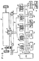
- Fig. 3 is a schematic diagram showing a printing device according to the embodiment of this invention.
- the printing device has printing hammer 1, ribbon 3 and platen 5 in the same positional relation as shown in Fig. 1.
- Belt 6 is entrained along platen 5.
- Printing hammer 1, printing wheel 7 having a plurality of spokes each having type 2 formed at the front end portion as shown in Fig. 1, cassette containing ink ribbon 3, and carriage 8 having a hammer solenoid, printing wheel motor, ribbon feed motor, etc. for driving these component parts, are provided on belt 6.
- Carriage 8 is so controlled that it can be moved from left to right, or vice versa, by carriage motor 9 connected to a pulley on belt 6.
- Platen 5 is rotated by paper feed motor 10 through a gear mechanism.
- U.S. Patent 4037208 or 4118129 discloses carriage 8 and various component parts on the carriage.
- Central processing unit (CPU) 11 executes various data processings in accordance with character codes and various control signals which are input from external host computer 12.
- CPU 11 controls ROM 16 for storing fixed data, such as a control program, through address bus 13, data bus 14 and control line 15 and RAM 17 for temporarily storing variable data, such as data input from host computer 12.
- Feed motor driver 18 for paper feed motor 10, wheel motor driver 19 for the printing wheel motor, ribbon motor driver 20 for the ribbon feed motor, hammer driver 21 for conducting current to a hammer solenoid of printing hammer 1, carriage motor driver 22 for carriage motor 9, I/0 interface 23 for receiving various data from host computer 12, timer 24 for counting time lapsing from the start of an operation of printing hammer 1, and switching circuit 25 including various kinds of control switches are connected to CPU 11 through data bus 14 and control line 15.
- Timer 24 is comprised of, for example, a timer counter and three time data registers. By comparing the contents of the timer counter with the respective contents of these time data registers a check is made as to whether or not a time lapses which is determined by time data stored in the aforementioned time data registers.
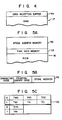
- Data reception buffer R1 for temporarily storing character codes and various instructions which are input to 1/0 interface 23 is formed in RAM 17 as shown in Fig. 4.
- ROM 16 includes not only a memory area for storing the aforementioned control program, but also a spoke address memory R2 and time data memory R3 as shown in Fig. 5A.
- spoke address memory R2 stores, for example, a spoke address showing the rotation position of the spokes of printing wheel 7 and energy code or data showing a printing energy level corresponding to the character code.
- the energy code "0” represents a smaller printing energy level
- the energy code "1” represents a greater printing energy level.
- the intensity of the printing energy is determined, depending upon the configuration of the types.
- the energy code "1" represents a greater contact area between the type and the ribbon and the energy code "0" represents a smaller contact area.
- time data memory R3 stores, with respect to the respective printing energy levels of the aforementioned energy codes "0"' and "1", drive inhibition times which are represented in terms of times lapsing from time to. That is, a time TWo required for printing hammer 1 to be returned to a position of type 2 on printing wheel 7, i.e., to a position corresponding to a distance D1 from a reference position after type 2 has been pushed against platen 5, time TR o required for printing hammer 1 to be returned to a position of printing ribbon 3, i.e., to a position corresponding to a distance D2 from the reference position and time TC o required for printing hammer 1 to be returned to a position substantially intermediate between platen 5 and printing ribbon 3, i.e., to a position corresponding to a distance (D2 + D3)/2 from the reference position, are stored in memory R3 with respect to the printing energy levels corresponding to the curve A in Fig. 2. Similarly, times TW 1 ,
- Time data memory R3 stores the turn-on times TH o and TH 1 which are determined in accordance with the respective printing energy codes "0" and "1" so that, at a time of printing, energization current flows through the hammer solenoid on printing hammer 1 for a time define by the turn-on time TH o to TH 1 .
- CPU 11 With the power supply of the printing device in an ON state, CPU 11 performs, subsequent to various initial processes, a printing process in accordance with a flow-chart as shown in Fig. 6. That is, at step P1, a check is made as to whether or not a character code or various control instruc-
- tion data are input from host computer 12 to I/0 interface 23. If the answer is YES, the input data is once stored in receiving buffer R1 in RAM 17. Then a check is made as to whether or not one or more data items are stored in receiving buffer R1. If the answer is YES, then the data item is read out to see what category it belongs to. If it is detected at step P2 that the data is not a character code, a check is made at step P3 as to whether or not there is a carriage drive instruction. If there is the carriage drive instruction, drive data is supplied to carriage motor driver 22 to start carriage motor 9 after the drive inhibition time TC for carriage 8 set in timer 24 has elapsed. Then the process goes back to step P1 so as to examine the data input of I/O interface 23.
- step P3 If at step P3 data read out of receiving buffer R1 is neither the character code nor the carriage drive instruction, CPU 11 judges that the data is another function instruction for change of lines, change of pages, tab-setting, etc. and executes a process corresponding to the instruction.
- step P2 If at step P2 the data read out of receiving buffer RI is detected as being the character code, CPU 11 judges that the printing cycle of the character corresponding to the character code is started. Thus the process goes to step P4.
- step P4 carriage motor 9 is started in the same way as mentioned above after the drive inhibition time TC for carriage 8 set to timer circuit 24 in the previous printing cycle has elapsed. If a start instruction of carriage motor 9 is sent to carriage motor driver 22, ribbon-feed motor is driven through ribbon motor driver 20 after the drive inhibition time TR for printing ribbon 3 set to timer 24 has elapsed.
- the drive inhibition times TW, TR and TC for printing wheel 7, printing ribbon 3 and carriage 8 are read out from time data memory R3 in ROM 16 in accordance with the printing energy used to print a character in a present printing cycle, and are then set to timer 20 when energization of hammer solenoid is started. That is, if the energy code of the character printed, for example, in a present printing cycle represents a small energy level "0", then drive inhibition times TWo, TR o and TC o are set to timer 24. When this is done, timer 24 is started, starting the count of the respective drive inhibition times. Then the process goes back to step P1 to check whether or not there is data in I/0 interface 23.
- the drive inhibition time TW from the drive start time to for printing hammer 1 until printing wheel 7 starts to move to a spoke address position corresponding to the next character code is set, depending upon a greater or a smaller printing energy level.
- the next printing wheel drive start timing is set faster than with a smaller printing energy with the result that it is possible to obtain a faster printing speed as a whole.
- Time data memory R3 stores the drive inhibition time TW for printing wheel 7 and drive inhibition times TR and TC for printing ribbon 3 and carriage 8 which correspond to this printing energy.
- Each time counter 24 has counted the respective drive inhibition times TC, TR and TW, carriage 8, printing ribbon 3 and printing wheel 7 are started to move.
- carriage 8 Since, in this way, carriage 8, printing ribbon 3 and printing wheel 7 are started in a sequence determined by the length of drive inhibition times, a whole time lapsing until the next character is printed can be reduced in comparison with the case where the aforementioned component parts are all moved at a time. If, for example, the same character is printed through printing wheel 7 or a character on a spoke which is adjacent to character on a spoke now printed is printed, a carriage drive time for the next character printing is set longer than the printing wheel setting time in which case carriage 8 is started earlier than printing wheel 7 to permit a whole operation time to be reduced.
- the three drive inhibition times TW, TR and TC for printing wheel 7, printing ribbon 3 and carriage 8 are stored in time data memory R3 so that they are started at the completion of sequentially counting the respective drive inhibition times by means of timer 24.
- a whole printing speed can also be increased even if printing wheel 7, printing ribbon 3 and carriage 8 are simultaneously started after the lapse of the drive inhibition time TW for printing wheel 7 which is stored, as the longest inhibition time, in time data memory R3.
- printing wheel 7 and carriage 8 can be started at the completion of counting the drive inhibition times TW and TC by means of timer 24 which are stored in time data memory R3, and the printing ribbon can started in synchronism with the drive starting time for printing wheel 7. Since the drive time is short for printing ribbon 3, the drive inhibition time for printing ribbon 3 may be always set to the drive inhibition time TR o which is determined as in Fig. 2 in the case of a smaller printing energy.
- the printing energy has been set to two levels, it may be set to three or more levels.
Landscapes
- Accessory Devices And Overall Control Thereof (AREA)
- Character Spaces And Line Spaces In Printers (AREA)
Claims (6)
caractérisé en ce qu'il comporte en outre
Applications Claiming Priority (2)
| Application Number | Priority Date | Filing Date | Title |
|---|---|---|---|
| JP83089/85 | 1985-04-18 | ||
| JP60083089A JPS61241171A (ja) | 1985-04-18 | 1985-04-18 | 印字装置 |
Publications (2)
| Publication Number | Publication Date |
|---|---|
| EP0199185A1 EP0199185A1 (fr) | 1986-10-29 |
| EP0199185B1 true EP0199185B1 (fr) | 1989-07-12 |
Family
ID=13792453
Family Applications (1)
| Application Number | Title | Priority Date | Filing Date |
|---|---|---|---|
| EP86104848A Expired EP0199185B1 (fr) | 1985-04-18 | 1986-04-09 | Dispositif d'impression |
Country Status (4)
| Country | Link |
|---|---|
| US (1) | US4710043A (fr) |
| EP (1) | EP0199185B1 (fr) |
| JP (1) | JPS61241171A (fr) |
| DE (1) | DE3664290D1 (fr) |
Families Citing this family (2)
| Publication number | Priority date | Publication date | Assignee | Title |
|---|---|---|---|---|
| US4940344A (en) * | 1984-07-30 | 1990-07-10 | Canon Kabushiki Kaisha | Printer having a variable interval between printing and carriage movement |
| JPS63179775A (ja) * | 1987-01-22 | 1988-07-23 | Brother Ind Ltd | 印字装置におけるキヤリツジ駆動装置 |
Family Cites Families (7)
| Publication number | Priority date | Publication date | Assignee | Title |
|---|---|---|---|---|
| CA1039217A (fr) * | 1974-07-01 | 1978-09-26 | Willy J. Grundherr | Systeme d'impression a roue tournante |
| US4037208A (en) * | 1976-05-03 | 1977-07-19 | Xerox Corporation | Hammer intensity selection apparatus for serial printer |
| US4293233A (en) * | 1978-12-06 | 1981-10-06 | Sci Systems, Inc. | Printer control system |
| JPS58890A (ja) * | 1981-06-26 | 1983-01-06 | Godo Shiyusei Kk | ウロキナ−ゼの回収法 |
| US4493570A (en) * | 1981-10-14 | 1985-01-15 | Ricoh Company, Ltd. | Control system for impact printer |
| JPS5865683A (ja) * | 1981-10-15 | 1983-04-19 | Canon Inc | 印字装置 |
| JPS60105559A (ja) * | 1983-11-14 | 1985-06-11 | Tokyo Electric Co Ltd | 印字装置 |
-
1985
- 1985-04-18 JP JP60083089A patent/JPS61241171A/ja active Pending
-
1986
- 1986-04-07 US US06/849,060 patent/US4710043A/en not_active Expired - Fee Related
- 1986-04-09 EP EP86104848A patent/EP0199185B1/fr not_active Expired
- 1986-04-09 DE DE8686104848T patent/DE3664290D1/de not_active Expired
Also Published As
| Publication number | Publication date |
|---|---|
| US4710043A (en) | 1987-12-01 |
| EP0199185A1 (fr) | 1986-10-29 |
| JPS61241171A (ja) | 1986-10-27 |
| DE3664290D1 (en) | 1989-08-17 |
Similar Documents
| Publication | Publication Date | Title |
|---|---|---|
| JPH0753467B2 (ja) | 電子タイプライタ | |
| US4224869A (en) | Parallel line printer | |
| JPS59188480A (ja) | オートパワーオフ機能付印字装置 | |
| EP0291099A1 (fr) | Appareil pour marquer la position d'origine d'un membre mobile | |
| US4710043A (en) | Impact printer with variable delay for print cycle based on different print-hammer energy levels | |
| KR0123531B1 (ko) | 시리얼 프린터의 캐리지 최적 제어방법 | |
| US5028157A (en) | Printer having an erasing mechanism | |
| US5048988A (en) | Ink sheet drive system for a recording device | |
| US4967205A (en) | Thermal head control device | |
| JP2552830B2 (ja) | バー・コード印字機能を持つプリンタ装置 | |
| US5120143A (en) | Solenoid energization current controlling apparatus | |
| JPH0356549B2 (fr) | ||
| US5147143A (en) | Printer carriage homing mechanism | |
| GB2255659A (en) | Speed control disengagement. | |
| EP0137463B1 (fr) | Imprimante à marguerite | |
| US4806029A (en) | Carriage drive unit for avoiding a loss time period in a printer | |
| JPH04152161A (ja) | ラベルプリンタ | |
| US4940344A (en) | Printer having a variable interval between printing and carriage movement | |
| JPS62158071A (ja) | 印字装置 | |
| GB2201640A (en) | Recording apparatus | |
| JPS62233273A (ja) | タイプライタ− | |
| JPH0393564A (ja) | 印字装置 | |
| JPS57157780A (en) | Correction of deviation of printing position in printer | |
| JPH01196368A (ja) | 紙送り装置 | |
| JPH05330118A (ja) | サーマルプリンタ |
Legal Events
| Date | Code | Title | Description |
|---|---|---|---|
| PUAI | Public reference made under article 153(3) epc to a published international application that has entered the european phase |
Free format text: ORIGINAL CODE: 0009012 |
|
| AK | Designated contracting states |
Kind code of ref document: A1 Designated state(s): DE FR GB |
|
| 17P | Request for examination filed |
Effective date: 19870311 |
|
| 17Q | First examination report despatched |
Effective date: 19880704 |
|
| GRAA | (expected) grant |
Free format text: ORIGINAL CODE: 0009210 |
|
| AK | Designated contracting states |
Kind code of ref document: B1 Designated state(s): DE FR GB |
|
| REF | Corresponds to: |
Ref document number: 3664290 Country of ref document: DE Date of ref document: 19890817 |
|
| ET | Fr: translation filed | ||
| PLBE | No opposition filed within time limit |
Free format text: ORIGINAL CODE: 0009261 |
|
| STAA | Information on the status of an ep patent application or granted ep patent |
Free format text: STATUS: NO OPPOSITION FILED WITHIN TIME LIMIT |
|
| 26N | No opposition filed | ||
| PGFP | Annual fee paid to national office [announced via postgrant information from national office to epo] |
Ref country code: FR Payment date: 19930317 Year of fee payment: 8 |
|
| PGFP | Annual fee paid to national office [announced via postgrant information from national office to epo] |
Ref country code: GB Payment date: 19930326 Year of fee payment: 8 |
|
| PGFP | Annual fee paid to national office [announced via postgrant information from national office to epo] |
Ref country code: DE Payment date: 19930630 Year of fee payment: 8 |
|
| PG25 | Lapsed in a contracting state [announced via postgrant information from national office to epo] |
Ref country code: GB Effective date: 19940409 |
|
| GBPC | Gb: european patent ceased through non-payment of renewal fee |
Effective date: 19940409 |
|
| PG25 | Lapsed in a contracting state [announced via postgrant information from national office to epo] |
Ref country code: FR Effective date: 19941229 |
|
| PG25 | Lapsed in a contracting state [announced via postgrant information from national office to epo] |
Ref country code: DE Effective date: 19950103 |
|
| REG | Reference to a national code |
Ref country code: FR Ref legal event code: ST |