EP0137463B1 - Imprimante à marguerite - Google Patents
Imprimante à marguerite Download PDFInfo
- Publication number
- EP0137463B1 EP0137463B1 EP84111947A EP84111947A EP0137463B1 EP 0137463 B1 EP0137463 B1 EP 0137463B1 EP 84111947 A EP84111947 A EP 84111947A EP 84111947 A EP84111947 A EP 84111947A EP 0137463 B1 EP0137463 B1 EP 0137463B1
- Authority
- EP
- European Patent Office
- Prior art keywords
- printing
- wheel
- type
- daisy
- hammer
- Prior art date
- Legal status (The legal status is an assumption and is not a legal conclusion. Google has not performed a legal analysis and makes no representation as to the accuracy of the status listed.)
- Expired
Links
- 235000005633 Chrysanthemum balsamita Nutrition 0.000 title claims description 41
- 241000132023 Bellis perennis Species 0.000 title description 2
- 241000723353 Chrysanthemum Species 0.000 claims description 39
- 230000004044 response Effects 0.000 claims description 8
- 239000011295 pitch Substances 0.000 description 54
- 230000002238 attenuated effect Effects 0.000 description 6
- 238000010586 diagram Methods 0.000 description 5
- 230000006870 function Effects 0.000 description 3
- 238000000034 method Methods 0.000 description 3
- 230000007246 mechanism Effects 0.000 description 2
- 230000008569 process Effects 0.000 description 2
- 230000007423 decrease Effects 0.000 description 1
- 238000010304 firing Methods 0.000 description 1
- 238000012986 modification Methods 0.000 description 1
- 230000004048 modification Effects 0.000 description 1
Images



Classifications
-
- B—PERFORMING OPERATIONS; TRANSPORTING
- B41—PRINTING; LINING MACHINES; TYPEWRITERS; STAMPS
- B41J—TYPEWRITERS; SELECTIVE PRINTING MECHANISMS, i.e. MECHANISMS PRINTING OTHERWISE THAN FROM A FORME; CORRECTION OF TYPOGRAPHICAL ERRORS
- B41J1/00—Typewriters or selective printing mechanisms characterised by the mounting, arrangement or disposition of the types or dies
- B41J1/22—Typewriters or selective printing mechanisms characterised by the mounting, arrangement or disposition of the types or dies with types or dies mounted on carriers rotatable for selection
- B41J1/24—Typewriters or selective printing mechanisms characterised by the mounting, arrangement or disposition of the types or dies with types or dies mounted on carriers rotatable for selection the plane of the type or die face being perpendicular to the axis of rotation
- B41J1/28—Carriers stationary for impression, e.g. with the types or dies not moving relative to the carriers
- B41J1/30—Carriers stationary for impression, e.g. with the types or dies not moving relative to the carriers with the types or dies moving relative to the carriers or mounted on flexible carriers
-
- B—PERFORMING OPERATIONS; TRANSPORTING
- B41—PRINTING; LINING MACHINES; TYPEWRITERS; STAMPS
- B41J—TYPEWRITERS; SELECTIVE PRINTING MECHANISMS, i.e. MECHANISMS PRINTING OTHERWISE THAN FROM A FORME; CORRECTION OF TYPOGRAPHICAL ERRORS
- B41J1/00—Typewriters or selective printing mechanisms characterised by the mounting, arrangement or disposition of the types or dies
- B41J1/22—Typewriters or selective printing mechanisms characterised by the mounting, arrangement or disposition of the types or dies with types or dies mounted on carriers rotatable for selection
- B41J1/24—Typewriters or selective printing mechanisms characterised by the mounting, arrangement or disposition of the types or dies with types or dies mounted on carriers rotatable for selection the plane of the type or die face being perpendicular to the axis of rotation
-
- B—PERFORMING OPERATIONS; TRANSPORTING
- B41—PRINTING; LINING MACHINES; TYPEWRITERS; STAMPS
- B41J—TYPEWRITERS; SELECTIVE PRINTING MECHANISMS, i.e. MECHANISMS PRINTING OTHERWISE THAN FROM A FORME; CORRECTION OF TYPOGRAPHICAL ERRORS
- B41J9/00—Hammer-impression mechanisms
- B41J9/44—Control for hammer-impression mechanisms
- B41J9/46—Control for hammer-impression mechanisms for deciding or adjusting hammer-firing time
Definitions
- the present invention relates to a daisy wheel type printing device.
- a daisy printing wheel is employed, for example, in the printing device associated with an electronic typewriter.
- the daisy printing wheel used in the printing device of this type is usually formed of a plurality of rectangular supporting plates arranged to extend radially from the center thereof. This printing wheel is arranged in a position facing a platen and driven by a stepping motor.
- the printing wheel is rotatably driven by the stepping motor, the type of the character to be printed is set in the printing position facing the paper on the platen, and the type is then struck by a printing hammer driven by a solenoid coil, thereby printing the desired character on the paper through an ink ribbon.
- a quiescent time which is slightly longer than the longest time required for attenuating the vibration to a sufficiently small value is set.
- the printing wheel is driven after this quiescent time has elapsed after the printing wheel has arrived at the designated position.
- the vibration generated at the supporting plates and the type of the printing wheel might be attenuated to have sufficiently small value within a time that is much shorter than the preset quiescent time when the printing wheel is driven to a designated position in accordance with a predetermined speed pattern. Even in this case, the printing hammer is not driven until the quiescent time has elapsed, and the average printing speed is accordingly lowered.
- IBM Technical Disclosure Bulletin, Vol. 21 No. 12 May 1979 shows a circuitry for a variable time delay for hammer firing in a rotating disk-type printer.
- EP-A-0 061 718 shows a serial printer comprising the mechanism for selecting one type by moving the mounted printing wheel and the carrier for moving said mechanism on the print sheet.
- the printing can be done at the maximum speed which is the optimum for the print wheel even in the case any kind of printing wheel is mounted.
- Carrier speed can be changed in accordance with the inertia of printing wheel and a shifting distance of printing wheel.
- An object of the present invention is to provide a daisy wheel type printing device which can enhance the printing speed of a daisy printing wheel by varying the period from the time when the printing wheel arrives at a designated position to the time when a printing hammer is driven in response to the number of pitches of the printing wheel.
- a daisy wheel type printing device comprising a daisy printing wheel having a plurality of type holding members having types at their respective ends, a drive unit for rotating the daisy printing wheel to set the type designated by input character data to a printing position, a printing hammer for hitting the type set in the printing position, and a control unit for driving the printing hammer with a delay of driving the hammer depending on detected speed variations in moving the printing system after a period of time selectively set in accordance with the rotation amount of the daisy printing wheel has elapsed after the type designated by the input character data arrived at the printing position.
- the standby or quiescent time is set to be short.
- the rotation amount of the printing wheel is small and the attenuating time of the vibration of the type is long, its standby time is set to be long, and the printing hammer is driven after the standby time has elapsed. Therefore, the type can always be printed after its vibration has been effectively attenuated, and the average printing speed can be improved.
- Fig. 1 shows a schematic speed pattern of a daisy printing wheel that can be moved from 1 to 50 pitches.
- the printing wheel When this printing wheel has moved, for example, 50 pitches, the printing wheel itself is rotated along with a speed pattern C50 as shown in Fig. 1.
- the printing wheel is rotated while being abruptly accelerated by increasing an exciting current flowing through an exciting coil of a stepping motor from an initial position to a sixth pitch position, and then is rotated at a predetermined speed, and is rotated to the fiftieth pitch position while being decelerated when the remaining pitch, for example, becomes six.
- the speed pattern of the printing wheel that has moved more than 13 pitches is substantially similar to the speed pattern C50 except that the period of constant-speed revolution is different.
- the printing wheel When the daisy printing wheel is moved to six pitches, the printing wheel is rotated along with the speed pattern C6 shown in Fig. 1. In other words, the printing wheel is rotated while being abruptly accelerated from the initial position to the third pitch position, and is then rotated from the third pitch position to the sixth pitch position while being decelerated.
- the daisy printing wheel arrives at the designated position, and a printing hammer is driven when the vibration of the supporting plates and of the type becomes sufficiently small.
- the vibration of the supporting plates and the type when the printing wheel is moved, for example, to the sixth pitch position is different from that when the wheel is moved to the 50th pitch position.
- the wheel is rotated at a constant speed from the sixth pitch position to the 44th pitch position, and is rotated from the 44th pitch position to the 50th pitch position while being decelerated.
- the vibration occurring at the supporting plates and at the type has a small value as shown in Fig.
- the predetermined standby time is set to be longer than the longest attenuating time of the vibration, such as 15 msec.
- the printing wheel is not driven until 15 msec. has elapsed even though the vibration of the supporting plates and the type has been attenuated to have a sufficiently small value upon the lapse of the approximately 8 msec. in a case where the printing wheel is driven at through 50 pitches.
- the average printing speed is lowered.
- Fig. 3 shows an electronic typewriter using a daisy wheel type printing device; according to one embodiment of the present invention, whose average printing speed has been improved.
- This typewriter has a housing 1 and a keyboard 2 provided at the front of the housing 1.
- characters keys In the keyboard 2 are arranged character keys, a space key, a carriage return key, a shift key, right and left margin keys, a tab set key and the like.
- a platen 3 is rotatably provided at the upper rear part of the housing 1 to hold a sheet 4.
- a printing device 5 carried on a carriage (not shown) is provided opposite the platen 3. This printing device prints the character corresponding to the character key operated by the known method on the sheet 4 set on the platen 3.
- the printing device 5 comprises, as shown in Fig. 4, a frame 11 fixedly secured to a carriage (not shown), a daisy printing wheel 12 rotatably mounted on the frame 11, a driver 13 for rotating the printing wheel 12, and a printing hammer 14.
- the daisy printing wheel 12 has, as shown in Fig. 5, a plurality of rectangular supporting plates 12-1 which extend radially from the center thereof, a plurality of types 12-2 mounted at the ends of the respective supporting plates 12-1, a plurality of recesses 12-3 formed within the circumference of the plates 12-1, and through holes 12-4 for indicating the home position.
- the driver 13 has a housing 13-1 which contains a stepping motor 13-2, and a coupler 13-3 which transmits the rotation of the motor 13-2 to the daisy printing wheel 12.
- the coupler 13-3 is formed to have projections which engage with the recesses 12-3 of the printing wheel 12 to transmit the rotation of the motor 13-2.
- a light source 15-1 is mounted on the housing 13-1. This light source 15-1 cooperates with a phototransistor 15-2 mounted on the frame 11 opposite the light source 15-1 to form a home position detector for detecting the through hole 12-4.
- One of the type 12-2 in the printing position faces the paper 4 on the platen 3 through a ribbon 16.
- Fig. 6 is a block diagram of a control circuit of an electronic typewriter shown in Fig. 4.
- This control circuit has a central processing unit (CPU) 100, a read only memory (ROM) 101 for storing a program to be executed by the CPU 100, and a random access memory (RAM) 102 for storing data processed by the CPU 100.
- CPU central processing unit
- ROM read only memory
- RAM random access memory
- To the CPU 100 are coupled a timer 104, a keyboard 106 and a solenoid 108 for driving a printing hammer 109 through a data bus.
- a stepping motor 114 to the CPU 100 are connected a stepping motor 114, a ribbon motor 115, a carriage motor 116 and a paper feed motor 117 through motor drivers 110 to 113.
- a home position detector 118 is composed of the light source 15-1 and the phototransistor 15-2 as shown in Fig. 4, and generates an output signal when detecting that the printing wheel 12 is set in the home position.
- the CPU 100 applies a drive command signal to the motor drivers 110 and 112 to rotate the stepping motor 114 and the carriage motor 116.
- the CPU 110 stops the carriage motor 116 upon detecting that the carriage has moved to the leftmost home position to set the carriage at the home position and to stop the stepping motor 114 in response to an output signal from the home position detector 118, thereby setting the daisy printing wheel 12 to the home position.
- the CPU 100 writes the pitch position data (0) in the memory area M1 of the RAM 102.
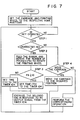
- the CPU 100 checks whether a key has been operated or not as in STEP 1.
- the CPU 100 checks to see whether or not the operated key is a character key as in STEP 2.
- the CPU 100 applies a drive command signal to the motor driver 111 to rotate the ribbon feed motor 115 by one step, thereby feeding an ink ribbon 16 at a predetermined distance.
- the CPU 100 calculates the number of pitches (PA) between the pitch position of the type designated by the character key thus operated and the pitch position represented by the pitch position data stored in the memory area M1, stores the number of pitches (PA) in the memory area M2, and stores data relating to direction to rotate the daisy printing wheel 12.
- the CPU 100 stores the pitch position data of the type designated by the operated character key in the memory area M1.
- the CPU 100 drives the carriage motor 116 through the motor driver 112 and supplies a drive command signal responsive to the directional data stored in the memory area M3 and to the number of pitches stored in the memory area M2 to the motor driver 110 while moving the carriage by one step, thereby rotating the stepping motor 114 by the number of corresponding steps in the designated direction.
- the type designated by the operated character key is set at the printing position, i.e., at the position opposite the printing hammer 14.
- the CPU 100 checks if the number of pitches (PA) stored in the memory area M2 is smaller than 13 as in STEP 3. When it is detected that the number of pitches (PA) is 13 or more, the CPU 100 sets time data (TO) in the timer 104, and sets the time data (T1) (T1 > TO) in the timer 104 when it is detected that the number of pitches (PA) is less than 13. The timer 104 generates an output signal to the CPU 100 after a period of time corresponding to the time data (TO) or (T1) thus set has elapsed.
- the CPU 100 supplies a drive signal to the solenoid 108 in response to the output signal from the timer 104, thereby driving the printing hammer 109 using the solenoid 108. Further, if the movement of the carriage is not yet complete, the CPU 100 does not respond to the output signal from the timer 104, and only applies a drive signal to the solenoid 108 when the movement of the carriage has been completed. Thus, the type set to the present printing position is printed on the sheet 4. After this printing has finished, the CPU 100 stands ready for the next keying operation in STEP 1.
- the CPU 100 checks whether or not the keying operation requires the movement of the carriage as in STEP 4. When it is detected that the operated function key is any one of the keys for moving the carriage such as the space key, the shift key and the carriage return key, the carriage is moved in response to this requirement, and the CPU 100 stands by the next key input in STEP 1.
- the printing hammer 14 is driven when a period of time T1, e.g., 15 msec. has elapsed, thereby executing the printing process. Further, in the case where the printing wheel 12 is rotated by 13 to 50 pitches, the printing hammer 14 is driven when a period of time TO, e.g., 9 msec. has elapsed, thereby executing the printing process.
- the printing hammer 14 is driven after a suitably short standby time which begins when the printing wheel 12 is rotated through 13 to 50 pitches and since the vibration of the supporting plates 12-1 and the type 12-2 is attenuated to have a sufficiently small value, the average printing speed can be enhanced.
- Fig. 8 shows the printing speed characteristics by a solid line A in a case where the standby time, when the daisy printing wheel is rotated through 0 to 12 pitches, is set to T1, and the standby time, when the printing wheel is rotated through 13 to 50 pitches, is set to T0.
- a broken line B in Fig. 8 shows the case where the standby time, when the printing wheel is rotated through 0 to 50 pitches, is set to T1.
- the maximum printing speed in this embodiment is limited by the speed of the stepping drive of the carriage, and is set to be 12 characters per second.
- the printing hammer 109 may be driven by energizing the solenoid 108 without setting the time data in the timer 104 when the number of pitches (PA) is 0 by first checking whether or not the number of pitches (PA) is 0 before checking whether or not the number of pitches (PA) is less than 13 as in STEP 3.
- the standby times TO and T1 are selectively set.
- the average printing speed may be further improved by selectively setting the timer 104 for the standby times in response to the number of pitches to be rotated and by employing more standby times of different lengths.
- the printing device associated with the electronic typewriter has been described.
- the printing device of the present invention may also be used, for example, as a printer for a computer.
- the CPU 100 may always supply a drive signal to the solenoid 108 in response to the output signal from the timer 104.
Landscapes
- Accessory Devices And Overall Control Thereof (AREA)
- Impact Printers (AREA)
Claims (4)
Applications Claiming Priority (2)
| Application Number | Priority Date | Filing Date | Title |
|---|---|---|---|
| JP187935/83 | 1983-10-07 | ||
| JP58187935A JPS6079956A (ja) | 1983-10-07 | 1983-10-07 | デイジ−ホイ−ル型印字装置の印字制御方式 |
Publications (3)
| Publication Number | Publication Date |
|---|---|
| EP0137463A2 EP0137463A2 (fr) | 1985-04-17 |
| EP0137463A3 EP0137463A3 (en) | 1986-07-02 |
| EP0137463B1 true EP0137463B1 (fr) | 1989-10-11 |
Family
ID=16214752
Family Applications (1)
| Application Number | Title | Priority Date | Filing Date |
|---|---|---|---|
| EP84111947A Expired EP0137463B1 (fr) | 1983-10-07 | 1984-10-05 | Imprimante à marguerite |
Country Status (6)
| Country | Link |
|---|---|
| US (1) | US4627752A (fr) |
| EP (1) | EP0137463B1 (fr) |
| JP (1) | JPS6079956A (fr) |
| KR (1) | KR900006929B1 (fr) |
| CA (1) | CA1225960A (fr) |
| DE (1) | DE3480072D1 (fr) |
Families Citing this family (3)
| Publication number | Priority date | Publication date | Assignee | Title |
|---|---|---|---|---|
| US4940344A (en) * | 1984-07-30 | 1990-07-10 | Canon Kabushiki Kaisha | Printer having a variable interval between printing and carriage movement |
| JPS62178369A (ja) * | 1986-01-31 | 1987-08-05 | Tokyo Juki Ind Co Ltd | 印字装置 |
| US5237247A (en) * | 1989-10-17 | 1993-08-17 | Sankyo Seiki Mfg. Co., Ltd. | Three-phase sine wave signal synthesizing circuit and brushless motor drive circuit using the same |
Family Cites Families (13)
| Publication number | Priority date | Publication date | Assignee | Title |
|---|---|---|---|---|
| FR2142938B1 (fr) * | 1970-01-29 | 1973-07-13 | Honeywell Inf Systems | |
| FR2249538A5 (en) * | 1973-10-24 | 1975-05-23 | Honeywell Bull Soc Ind | Printing machine hammer energy control - has adjustable time delay between hammers and impulse generator |
| JPS52108732A (en) * | 1976-03-10 | 1977-09-12 | Oki Electric Ind Co Ltd | Dot printer |
| US4189246A (en) * | 1977-12-22 | 1980-02-19 | International Business Machines Corporation | Variable print-hammer control for on-the-fly-printing |
| US4353020A (en) * | 1978-11-01 | 1982-10-05 | Plessey Peripheral Systems | Impact printer programmed servo system |
| JPS55118883A (en) * | 1979-03-08 | 1980-09-12 | Ricoh Co Ltd | Printing system of serial printer |
| GB2079680B (en) * | 1980-07-09 | 1984-04-11 | Pa Management Consult | Daisy wheel printer |
| JPS57138969A (en) * | 1981-02-20 | 1982-08-27 | Brother Ind Ltd | Electronic typewriter |
| JPS57197189A (en) * | 1981-03-30 | 1982-12-03 | Fujitsu Ltd | Control system for serial printer |
| US4493570A (en) * | 1981-10-14 | 1985-01-15 | Ricoh Company, Ltd. | Control system for impact printer |
| JPS5876279A (ja) * | 1981-11-02 | 1983-05-09 | Ricoh Co Ltd | インパクトプリンタ |
| JPS5867484A (ja) * | 1981-10-16 | 1983-04-22 | Canon Inc | 印字装置 |
| US4502800A (en) * | 1982-07-08 | 1985-03-05 | 501 Qume Corporation | Daisywheel printer |
-
1983
- 1983-10-07 JP JP58187935A patent/JPS6079956A/ja active Pending
-
1984
- 1984-09-22 KR KR1019840005819A patent/KR900006929B1/ko not_active Expired
- 1984-10-01 US US06/656,456 patent/US4627752A/en not_active Expired - Fee Related
- 1984-10-05 EP EP84111947A patent/EP0137463B1/fr not_active Expired
- 1984-10-05 DE DE8484111947T patent/DE3480072D1/de not_active Expired
- 1984-10-05 CA CA000464895A patent/CA1225960A/fr not_active Expired
Also Published As
| Publication number | Publication date |
|---|---|
| JPS6079956A (ja) | 1985-05-07 |
| EP0137463A2 (fr) | 1985-04-17 |
| EP0137463A3 (en) | 1986-07-02 |
| CA1225960A (fr) | 1987-08-25 |
| US4627752A (en) | 1986-12-09 |
| KR850003706A (ko) | 1985-06-26 |
| DE3480072D1 (en) | 1989-11-16 |
| KR900006929B1 (ko) | 1990-09-25 |
Similar Documents
| Publication | Publication Date | Title |
|---|---|---|
| US4284362A (en) | Printer control logic | |
| US4655620A (en) | Spelling error finding feature including an electronic spelling dictionary | |
| US3724631A (en) | Printer with helically arranged type divided into axially offset group | |
| US4627752A (en) | Daisy wheel printing device with variable hammer delay | |
| US5454653A (en) | Printing device having record medium feed means | |
| US3749223A (en) | Electronic tabulation control system for recorder | |
| US4405245A (en) | Variable speed signal printing apparatus | |
| US5028157A (en) | Printer having an erasing mechanism | |
| JPS6411468B2 (fr) | ||
| US5147143A (en) | Printer carriage homing mechanism | |
| US5501534A (en) | Electronic apparatus which is automatically initialized when normal operation is resumed after the apparatus has been in a low power consumption mode | |
| US4810117A (en) | Printer with a ribbon lift mechanism having selective time intervals either in typewriter mode or in printer mode | |
| JPS6043528B2 (ja) | 電子タイプライタ | |
| US4806029A (en) | Carriage drive unit for avoiding a loss time period in a printer | |
| JPH0326655B2 (fr) | ||
| JPS62233273A (ja) | タイプライタ− | |
| US3977319A (en) | Drum column printer | |
| EP0199185B1 (fr) | Dispositif d'impression | |
| US4940344A (en) | Printer having a variable interval between printing and carriage movement | |
| US5051012A (en) | Carriage positioning for multiple impact printing | |
| US5230283A (en) | Print hammer position control device | |
| JPS596238B2 (ja) | 電子式タイプライタ | |
| JPS61262165A (ja) | 印字制御装置 | |
| JPH03124467A (ja) | 電子タイプライタ | |
| JPS6027578B2 (ja) | 印字装置 |
Legal Events
| Date | Code | Title | Description |
|---|---|---|---|
| PUAI | Public reference made under article 153(3) epc to a published international application that has entered the european phase |
Free format text: ORIGINAL CODE: 0009012 |
|
| AK | Designated contracting states |
Designated state(s): DE FR GB IT |
|
| PUAL | Search report despatched |
Free format text: ORIGINAL CODE: 0009013 |
|
| AK | Designated contracting states |
Kind code of ref document: A3 Designated state(s): DE FR GB IT |
|
| 17P | Request for examination filed |
Effective date: 19870102 |
|
| 17Q | First examination report despatched |
Effective date: 19880414 |
|
| GRAA | (expected) grant |
Free format text: ORIGINAL CODE: 0009210 |
|
| AK | Designated contracting states |
Kind code of ref document: B1 Designated state(s): DE FR GB IT |
|
| PG25 | Lapsed in a contracting state [announced via postgrant information from national office to epo] |
Ref country code: IT Free format text: LAPSE BECAUSE OF FAILURE TO SUBMIT A TRANSLATION OF THE DESCRIPTION OR TO PAY THE FEE WITHIN THE PRESCRIBED TIME-LIMIT;WARNING: LAPSES OF ITALIAN PATENTS WITH EFFECTIVE DATE BEFORE 2007 MAY HAVE OCCURRED AT ANY TIME BEFORE 2007. THE CORRECT EFFECTIVE DATE MAY BE DIFFERENT FROM THE ONE RECORDED. Effective date: 19891011 Ref country code: FR Free format text: THE PATENT HAS BEEN ANNULLED BY A DECISION OF A NATIONAL AUTHORITY Effective date: 19891011 |
|
| REF | Corresponds to: |
Ref document number: 3480072 Country of ref document: DE Date of ref document: 19891116 |
|
| EN | Fr: translation not filed | ||
| PLBE | No opposition filed within time limit |
Free format text: ORIGINAL CODE: 0009261 |
|
| STAA | Information on the status of an ep patent application or granted ep patent |
Free format text: STATUS: NO OPPOSITION FILED WITHIN TIME LIMIT |
|
| 26N | No opposition filed | ||
| PG25 | Lapsed in a contracting state [announced via postgrant information from national office to epo] |
Ref country code: GB Effective date: 19901005 |
|
| GBPC | Gb: european patent ceased through non-payment of renewal fee | ||
| PGFP | Annual fee paid to national office [announced via postgrant information from national office to epo] |
Ref country code: DE Payment date: 19931228 Year of fee payment: 10 |
|
| PG25 | Lapsed in a contracting state [announced via postgrant information from national office to epo] |
Ref country code: DE Effective date: 19950701 |