EP0200650B1 - Vorrichtung und Verfahren zur Messung der Festigkeit einer Materialbahn - Google Patents
Vorrichtung und Verfahren zur Messung der Festigkeit einer Materialbahn Download PDFInfo
- Publication number
- EP0200650B1 EP0200650B1 EP86400930A EP86400930A EP0200650B1 EP 0200650 B1 EP0200650 B1 EP 0200650B1 EP 86400930 A EP86400930 A EP 86400930A EP 86400930 A EP86400930 A EP 86400930A EP 0200650 B1 EP0200650 B1 EP 0200650B1
- Authority
- EP
- European Patent Office
- Prior art keywords
- sheet
- strength
- velocity
- localized areas
- rolls
- Prior art date
- Legal status (The legal status is an assumption and is not a legal conclusion. Google has not performed a legal analysis and makes no representation as to the accuracy of the status listed.)
- Expired - Lifetime
Links
- 238000000034 method Methods 0.000 title claims description 14
- 239000000463 material Substances 0.000 title claims description 10
- XLYOFNOQVPJJNP-UHFFFAOYSA-N water Substances O XLYOFNOQVPJJNP-UHFFFAOYSA-N 0.000 description 5
- 230000005611 electricity Effects 0.000 description 2
- 238000007373 indentation Methods 0.000 description 2
- 238000004519 manufacturing process Methods 0.000 description 2
- 238000005259 measurement Methods 0.000 description 2
- 238000002604 ultrasonography Methods 0.000 description 2
- 230000005540 biological transmission Effects 0.000 description 1
- 230000007423 decrease Effects 0.000 description 1
- 230000001066 destructive effect Effects 0.000 description 1
- 239000000835 fiber Substances 0.000 description 1
- 238000010304 firing Methods 0.000 description 1
- 239000000203 mixture Substances 0.000 description 1
- 230000001360 synchronised effect Effects 0.000 description 1
Images
Classifications
-
- G—PHYSICS
- G01—MEASURING; TESTING
- G01N—INVESTIGATING OR ANALYSING MATERIALS BY DETERMINING THEIR CHEMICAL OR PHYSICAL PROPERTIES
- G01N33/00—Investigating or analysing materials by specific methods not covered by groups G01N1/00 - G01N31/00
- G01N33/34—Paper
-
- G—PHYSICS
- G01—MEASURING; TESTING
- G01N—INVESTIGATING OR ANALYSING MATERIALS BY DETERMINING THEIR CHEMICAL OR PHYSICAL PROPERTIES
- G01N3/00—Investigating strength properties of solid materials by application of mechanical stress
- G01N3/08—Investigating strength properties of solid materials by application of mechanical stress by applying steady tensile or compressive forces
-
- G—PHYSICS
- G01—MEASURING; TESTING
- G01N—INVESTIGATING OR ANALYSING MATERIALS BY DETERMINING THEIR CHEMICAL OR PHYSICAL PROPERTIES
- G01N33/00—Investigating or analysing materials by specific methods not covered by groups G01N1/00 - G01N31/00
- G01N33/34—Paper
- G01N33/346—Paper sheets
-
- G—PHYSICS
- G01—MEASURING; TESTING
- G01N—INVESTIGATING OR ANALYSING MATERIALS BY DETERMINING THEIR CHEMICAL OR PHYSICAL PROPERTIES
- G01N2203/00—Investigating strength properties of solid materials by application of mechanical stress
- G01N2203/02—Details not specific for a particular testing method
- G01N2203/026—Specifications of the specimen
- G01N2203/0262—Shape of the specimen
- G01N2203/0278—Thin specimens
-
- G—PHYSICS
- G01—MEASURING; TESTING
- G01N—INVESTIGATING OR ANALYSING MATERIALS BY DETERMINING THEIR CHEMICAL OR PHYSICAL PROPERTIES
- G01N2203/00—Investigating strength properties of solid materials by application of mechanical stress
- G01N2203/02—Details not specific for a particular testing method
- G01N2203/026—Specifications of the specimen
- G01N2203/0262—Shape of the specimen
- G01N2203/0278—Thin specimens
- G01N2203/0282—Two dimensional, e.g. tapes, webs, sheets, strips, disks or membranes
Definitions
- the present invention concerns a system for measuring the strength of a sheet such as paper while the sheet is being produced.
- strength of paper can be measure in various ways including burst, tensile and pierce strengths. Normally, these strength parameters are determined by various destructive tests in a laboratory. However, on-line determination of paper strength during the manufacture of paper can aid in producing paper which can meet specified strength requirements.
- U.S. Patent 4,291,577 teaches a system for measuring the strength of paper as it is being produced.
- the patent provides for measurement of the velocity of ultrasonic waves through the moving paper sheet. Based upon the velocity, the strength of the paper is determined.
- the patent teaches a device having two wheels which are spaced apart from one another and which roll along the moving paper web.
- the first wheel contains a transducer in the form of a rectangular button mounted on the periphery of the wheel so that as the wheel rotates the button periodically contacts the paper. Each revolution of the wheel, when the transducer contacts the paper, it receives an electrical signal from a signal generator and imparts a mechanical signal to the paper.
- the second wheel contains a receiving transducer substantially the same as the transmitting transducer, which also is mounted on the periphery of the wheel and occupies a small percentage of the total circumference of the wheel.
- the receiving transducer contacts the paper once each revolution of the wheel and receives the signal from the transmitter by picking up the ultrasound signal from the paper and converting it to an electrical signal.
- the system also includes a position detector to monitor the rotational position of the first wheel and to trigger the firing of the ultrasound pulse by the transmitter when the wheel is in a predetermined position.
- the rotation of the receiving wheel is coordinated with the transmitting wheel so that the receiving transducer is in contact with the paper at the appropriate time to receive the transmitted signal.
- the signal from the receiving transducer is transmitted to a metering and recording apparatus which measures the velocity of the ultrasonic waves.
- the system described in the patent has a number of disadvantages. Since the transmitting transducer and the receiving transducer each contact the paper during only a small percentage of the total rotation of the wheels, the rotation of the wheels must be carefully synchronized and the transmission of the pulse must be carefully timed so that the pulse is received by the transmitter when it is in contact with the paper. Furthermore, since the transmitter and the receiver are only in contact with the paper for a small percentage of the total rotation of the wheels, a substantial portion of the paper is not subject to velocity measurement.
- An object of the present invention is to provide a system and process for continuously measuring the strength of a moving sheet.
- a further object is to provide such a system which utilizes the tension and elastic modulus of the sheet and also the velocity of the sheet to determine strength.
- the present invention provides a system for non-destructively determining the strength of a sheet of material being drawn under tension to travel between a first roll and a second roll, the sheet of material having a width, the system comprising:
- the present invention further provides a process for non-destructively determining the strength of a sheet which is being drawn under tension between a first roll and a second roll comprising the steps of:
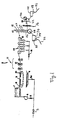
- Figure 1 is a schematic illustration of the present embodiment.
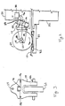
- FIG. 2 is an illustration of part of the present embodiment.
- Figure 3 is a top view of the part shown in Figure 2.
- sheet 10 is passed through press 11 consisting of a plurality of rollers 12 which removes much of the water from sheet 10. Thereafter the paper sheet passes into a dryer section 14 consisting of a plurality of rollers 15 through which steam is supplied by a steam control valve 16. The steam heats the rollers and consequently evaporates much of the water in the paper sheet so that the paper emerging from dryer section 14 has the desired moisture content.
- the paper passes from dryer section 14 to a calendar stack 17.
- the calendar stack 17 includes a plurality of calendar rollers 18, 20, 22, 24, 26 and 28.
- the bottom most roller, 28, is larger than the other rollers and is driven by a motor 30 which is powered by electricity from line 32. Electricity from line 32 is supplied to the motor 30 through an ammeter 34 which measures the current passing through line 32.
- a tachometer 35 is coupled to the motor 30 to measure the speed of the motor.
- the sheet After leaving the calendar rolls 26 and 28, the sheet passes through scanner 36 and is wound onto reel 40.
- the reel 40 is driven to rotate by a pope roll 42 which in turn is rotated by motor 44.
- the motor 44 receives electric current through line 46 and ammeter 48.
- the scanner 36 is conventional and will therefore not be discussed in detail herein. Basically, the scanner 36 includes two heads, one disposed above and the other below the sheet of paper.
- the scanner 36 also includes a drive system to cause the scanners to reciprocate back and forth across the moving sheet of paper. Further details of a scanner can be ascertained from U.S. Patent 3,621,259 titled "Sheet-Gauging Apparatus".
- FIG. 2 and 3 there is shown part of an upper gauging head 50 and part of a lower gauging head 52. Both heads 50 and 52 are coupled to the scanner 36 so that they can be moved back and forth across the moving sheet of paper.
- a support member 54 is coupled to the upper gauging head 50 by pivot 55.
- the support member includes two brackets 56 mounted at its lower end, and a U-shaped bracket 58 is coupled to the brackets 56 by pivot 57.
- the U-shaped bracket 58 can rotate horizontally about pivot 55 and vertically about pivot 57.
- a wheel 60 is mounted in the U-shaped bracket 57 by an axle 62 on bearings, not shown.
- the wheel 60 is free to rotate as indicated by the arrow and also to move upward and downward as the bracket 58 rotates about the pivot 57.
- the support member 54 includes an indentation 66 adjacent the upper part of U-shaped bracket 58.
- a load cell 70 is coupled to the support member 54 in the indentation 66 and also to the bracket 58.
- the load cell 70 is a conventional device to measure the compressive force on the load cell and generate a signal corresponding to the compressive force. Thus it can be seen that the load cell 70 measures the upward force on the wheel 60.
- the load cell 70 is coupled by line 71 to transmit signals to a computing system 72 mounted In the upper gauging head 50.
- a tachometer 74 is coupled to the bracket 58 and to the axle 62 to measure the rate of rotation of the wheel and generate a signal corresponding thereto.
- the signals from the tachometer 74 are conveyed to the computing system 72 by a line 76.
- a support 80 is coupled to the lower gauging head 52, below the sheet 10, and a sheet support member 82 is coupled to the support 80.
- the sheet support member 82 is substantially toroidal in shape and has a smooth, rounded upper surface.
- the wheel 60 is mounted above the sheet of paper 10, and the sheet support member 82 is mounted directly below the wheel, and on the opposite side of the sheet of paper.
- the wheel 60 and sheet support member 82 are positioned so that the sheet 10 is in contact with the upper surface of the support member 82, and the wheel 60 pushes the paper in the center of the support member 82 downwardly a predetermined distance which in practice can be about 0.2 - 0.5 centimeters, and preferably about 0.4 centimeters, below the upper edge of the support member 82 for a support member 82 about 12,7 cm (5 inches) in diameter.
- tension and elastic modulus i.e. the ratio of stress to strain in the paper
- the computer 72 receives signals from the load cell 70 corresponding to the tension and elastic modulus in the paper and signals from the tachometer 74 corresponding to the velocity of the paper.
- the computing system 72 utilizes the data to determine the strength of the sheet of paper as will be discussed in more detail hereinafter.
- the support member 54 and wheel 60 pivot slightly about pivot 55 so that the wheel 60 rolls smoothly on the sheet.
- the computing system 72 receives signals from the ammeter 34 which measures the load on the motor 30 driving calendar roller 28.
- the load on motor 30 is representative of the average tension on the sheet of paper between rollers 15 and the first calendar stack roller 18.
- the computing system 72 also receives signals from the ammeter 48 which indicate the load on the motor 44 which in turn is representative of the tension on the sheet 10 between the calendar roller 28 and the pope roll 42.
- the computing system 72 also receives signals from tachometer 35 measuring the speed of motor 30, which is representative of the speed of the sheet of paper 10 as it passes over roller 28.
- the computing system 72 utilizes the parameters discussed above to determine the strength of the paper according to the following equation: Where:
- the density ⁇ in this case can be determined utilizing the conventionally measured parameters of basis weight and caliper wherein density equals basis weight divided by caliper.
Landscapes
- Health & Medical Sciences (AREA)
- Life Sciences & Earth Sciences (AREA)
- Chemical & Material Sciences (AREA)
- Pathology (AREA)
- Physics & Mathematics (AREA)
- Analytical Chemistry (AREA)
- Biochemistry (AREA)
- General Health & Medical Sciences (AREA)
- General Physics & Mathematics (AREA)
- Immunology (AREA)
- Food Science & Technology (AREA)
- Medicinal Chemistry (AREA)
- Engineering & Computer Science (AREA)
- Investigating Strength Of Materials By Application Of Mechanical Stress (AREA)
- Paper (AREA)
- Force Measurement Appropriate To Specific Purposes (AREA)
Claims (13)
- System zur zerstörungsfreien Bestimmung der Festigkeit einer Materialbahn (10), die sich zwischen einer ersten Walze und einer zweiten Walze (28, 42) bewegend unter Spannung gezogen wird, wobei die Materialbahn eine Breite hat, wobei das System umfaßt:a) eine Befestigungseinrichtung (50, 52), die so angeordnet ist, daß sie einen Lastsensor über die Breite der Bahn beweglich trägt, während sich die Bahn zwischen der ersten und der zweiten Walze bewegt;b) einen Lastsensor (54-58, 60, 62, 70, 80, 82), der an der Befestigungseinrichtung angebracht ist und mit der Bahn in Kontakt ist, wobei der Lastsensor eine Einrichtung zum gesteuerten Durchbiegen der Bahn über einen örtlich begrenzten Bereich zwischen der ersten und der zweiten Walze enthält, wobei der Lastsensor die Kraft, die durch die Bahn gegen die Durchbiegeeinrichtung ausgeübt wird, an einer Vielzahl von örtlich begrenzten Bereichen zwischen der ersten und der zweiten Walze erfaßt und Signale erzeugt, die der Kraft entsprechen; undc) eine Recheneinrichtung (72) zum Empfang und zur Verarbeitung der Signale vom Lastsensor, die eine Anzeige der Festigkeit der Bahn in einem örtlich begrenzten Bereich in bezug auf die Festigkeit in wenigstens einem anderen örtlich begrenzten Bereich erzeugt.
- System zur zerstörungsfreien Bestimmung der Festigkeit einer Materialbahn (10), die sich unter Spannung zwischen einer ersten und einer zweiten Walze (28, 42) bewegt, wobei die Materialbahn eine Breite hat, wobei das System umfaßt:a) eine Befestigungseinrichtung (50, 52), die einen Lastsensor trägt, der sich über die Breite der Materialbahn bewegt, während sich die Bahn zwischen der ersten und der zweiten Walze bewegt;b) einen Lastsensor (54-58, 60, 62, 70, 80, 82), der an der Befestigungseinrichtung angebracht ist und mit der Bahn in Kontakt ist, wobei der Lastsensor eine Einrichtung zum gesteuerten Durchbiegen der Bahn über einen örtlich begrenzten Bereich zwischen der ersten und der zweiten Walze enthält, wobei der Lastsensor eine Einrichtung zur Ermittlung der für das Durchbiegen erforderlichen Kraft und zur Erzeugung eines Ausgangssignals, das die Kraft anzeigt, enthält;c) eine Geschwindigkeitsermittlungseinrichtung (74) zur Ermittlung der Geschwindigkeit der Bahn innerhalb des örtlich begrenzten Bereichs und zur Erzeugung von Signalen, die die Geschwindigkeit anzeigen; undd) eine Recheneinrichtung (72) zum Empfang und zur Verarbeitung der Ausgangssignale vom Lastsensor und der Geschwindigkeitsermittlungseinrichtung, die eine Ausgabe erzeugt, die die Festigkeit der Bahn anzeigt.
- System nach Anspruch 2, wobei die Bahndurchbiegeeinrichtung ein Rad (60) enthält, das mit der Bahn in Kontakt ist und sie durchbiegt, und die Geschwindigkeitsermittlungseinrichtung Ausgangssignale erzeugt, die die Drehgeschwindigkeit des Rades und damit die Geschwindigkeit der Bahn (10) innerhalb des örtlich begrenzten Bereichs anzeigt.
- System nach Anspruch 3, das des weiteren eine Dichteerfassungseinrichtung enthält, die die Dichte der Bahn (10) erfaßt und Signale, die der erfaßten Dichte entsprechen, zur Recheneinrichtung (72) leitet, wobei die Recheneinrichtung eine Anzeige der Festigkeit der Bahn auf der Grundlage von Signalen erzeugt, die von dem Lastsensor, von der Dichteerfassungseinrichtung und der Geschwindigkeitsermittlungseinrichtung erzeugt werden.
- System nach Anspruch 3, das eine zweite Geschwindigkeitsermittlungseinrichtung (35) zur Erzeugung von Ausgangssignalen enthält, die die Geschwindigkeit der Bahn (10) an einer Stelle zwischen der ersten und der zweiten Walze außerhalb des örtlich begrenzten Bereichs anzeigen, wobei das System des weiteren eine Spannungserfassungseinrichtung (30, 34) enthält, die angebracht ist, um die durchschnittliche auf die Bahn wirkende Spannung zu erfassen und Ausgangssignale zu erzeugen, die die durchschnittliche Spannung anzeigen, wobei die Recheneinrichtung (72) eine Anzeige der Festigkeit der Bahn auf der Grundlage der Signale erzeugt, die durch den Lastsensor, die erste und die zweite Geschwindigkeitsermittlungseinrichtung und die Spannungserfassungseinrichtung erzeugt werden.
- Verfahren zur zerstörungsfreien Bestimmung der Festigkeit einer Bahn (10), die unter Spannung zwischen einer ersten Walze und einer zweiten Walze (28, 42) gezogen wird, das die folgenden Schritte umfaßt:a) Ermittlung einer in einer Vielzahl von örtlich begrenzten Bereichen zwischen der ersten und der zweiten Walze auf die Bahn wirkenden Durchbiegelast; undb) Berechnung der relativen Festigkeit der Bahn in wenigstens einem der örtlich begrenzten Bereiche im Vergleich zur Festigkeit in wenigstens einem anderen örtlich begrenzten Bereich auf der Grundlage ermittelter Durchbiegelasten, während sich die Bahn zwischen der ersten und der zweiten Walze bewegt.
- Verfahren nach Anspruch 6, wobei der Berechnungsschritt das Auffinden von Werten gemäß der folgenden Gleichung umfaßt:

wobei:S1 und S2 = Festigkeiten in zwei örtlich begrenzten Bereichen;L1 und L2 = Lasten in den gleichen beiden örtlich begrenzten Bereichen; undK = eine Konstante. - Verfahren zur zerstörungsfreien Bestimmung der Festigkeit einer Materialbahn (10), die sich unter Spannung zwischen einer ersten Walze und einer zweiten Walze (28, 42) bewegt, wobei das Verfahren die folgenden Schritte umfaßt:a) gesteuertes Durchbiegen der Bahn über einen örtlich begrenzten Bereich zwischen der ersten und der zweiten Walze;b) Ermittlung der durch die Bahn ausgeübten Kräfte, wenn die Bahn in einer Vielzahl von örtlich begrenzten Bereichen zwischen der ersten und der zweiten Walze durchgebogen wird;c) Ermittlung der Geschwindigkeit der sich bewegenden Bahn in den örtlich begrenzten Bereichen; undd) Berechnung der Festigkeit der Bahn in wenigstens einem der örtlich begrenzten Bereiche auf der Grundlage der Geschwindigkeit der Bahn in den örtlich begrenzten Bereichen und der Durchbiegekräfte in den örtlich begrenzten Bereichen.
- Verfahren nach Anspruch 8, wobei der Berechnungsschritt das Auffinden von Werten gemäß der folgenden Gleichung umfaßt:
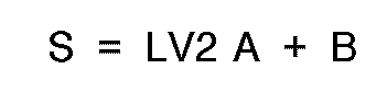
wobei:S = Festigkeit;A und B = Konstanten;L = die Durchbiegekraft; undV2 = ermittelte Geschwindigkeit der Bahn in den örtlich begrenzten Bereichen. - Verfahren nach Anspruch 8, das des weiteren den folgenden Schritt enthält:
Ermittlung der Dichte der sich bewegenden Bahn (10), und wobei die Berechnung der Festigkeit der Bahn des weiteren auf der erfaßten Dichte beruht. - Verfahren nach Anspruch 10, wobei der Berechnungsschritt das Auffinden von Werten gemäß der folgenden Gleichung umfaßt:

wobei:S = Festigkeit;L = Last;V2 = Geschwindigkeit der Bahn in den örtlich begrenzten Bereichen;A2 und B2 = Konstanten; undρ = Dichte. - Verfahren nach Anspruch 8, das des weiteren die folgenden Schritte enthält:
Ermittlung der Geschwindigkeit der Bahn (10) an einem Punkt zwischen der ersten und der zweiten Walze (28, 42), der von den örtlich begrenzten Bereichen entfernt ist; und
Ermittlung der durchschnittlichen Spannung der sich bewegenden Bahn, und wobei die Berechnung der Festigkeit der Bahn des weiteren auf der ermittelten Entfernungsgeschwindigkeit und der ermittelten Durchschnittsspannung beruht. - Verfahren nach Anspruch 12, wobei der Berechnungsschritt das Auffinden von Werten gemäß der folgenden Gleichung umfaßt:
 S = Festigkeit;C und K = Konstanten;L = erfaßte Last;T = durchschnittliche Spannung;V2 = Geschwindigkeit der Bahn in den örtlich begrenzten Bereichen; undV1 = Geschwindigkeit in Entferung von den örtlich begrenzten Bereichen.
Applications Claiming Priority (2)
| Application Number | Priority Date | Filing Date | Title |
|---|---|---|---|
| US73040685A | 1985-05-02 | 1985-05-02 | |
| US730406 | 1985-05-02 |
Publications (3)
| Publication Number | Publication Date |
|---|---|
| EP0200650A2 EP0200650A2 (de) | 1986-11-05 |
| EP0200650A3 EP0200650A3 (en) | 1989-10-25 |
| EP0200650B1 true EP0200650B1 (de) | 1993-12-08 |
Family
ID=24935215
Family Applications (1)
| Application Number | Title | Priority Date | Filing Date |
|---|---|---|---|
| EP86400930A Expired - Lifetime EP0200650B1 (de) | 1985-05-02 | 1986-04-28 | Vorrichtung und Verfahren zur Messung der Festigkeit einer Materialbahn |
Country Status (7)
| Country | Link |
|---|---|
| EP (1) | EP0200650B1 (de) |
| JP (1) | JPH0785046B2 (de) |
| KR (1) | KR920006033B1 (de) |
| CA (1) | CA1252894A (de) |
| DE (1) | DE3689362T2 (de) |
| FI (1) | FI89836C (de) |
| IT (1) | IT1212124B (de) |
Families Citing this family (11)
| Publication number | Priority date | Publication date | Assignee | Title |
|---|---|---|---|---|
| DE3787227T2 (de) | 1986-07-18 | 1994-04-07 | Measurex Corp | Sensor zur Ermittlung der Stärke bandförmiger Materialien. |
| US5104488A (en) * | 1987-10-05 | 1992-04-14 | Measurex Corporation | System and process for continuous determination and control of paper strength |
| US5013403A (en) * | 1987-10-05 | 1991-05-07 | Measurex Corporation | Process for continuous determination of paper strength |
| US4936140A (en) * | 1988-01-22 | 1990-06-26 | Measurex Corporation | Device and method for calibrating a non-destructive sheet strength measuring system |
| US5029469A (en) * | 1988-06-17 | 1991-07-09 | Measurex Corporation | Sheet tension sensor |
| JPH032239U (de) * | 1989-05-29 | 1991-01-10 | ||
| JPH0786451B2 (ja) * | 1989-08-29 | 1995-09-20 | 三井造船株式会社 | 打撃検査方法および装置 |
| SE513007C2 (sv) * | 1998-02-25 | 2000-06-19 | Lorentzen & Wettre Ab | Förfarande och anordning för att mäta dragstyrkan hos papper eller papp i z-riktningen |
| DE102005054825A1 (de) * | 2005-11-15 | 2007-05-24 | Voith Patent Gmbh | Verfahren zur Bestimmung der Papierfestigkeit |
| KR100659837B1 (ko) * | 2005-11-29 | 2006-12-19 | 삼성에스디아이 주식회사 | 이차 전지의 전극 활물질 도포 방법 및 장치 |
| DE102005058142A1 (de) * | 2005-12-06 | 2007-06-21 | Voith Patent Gmbh | Verfahren zur Bestimmung einer Dehnungseigenschaft einer Papierbahn |
Family Cites Families (6)
| Publication number | Priority date | Publication date | Assignee | Title |
|---|---|---|---|---|
| CH475609A (de) * | 1967-06-15 | 1969-07-15 | Sodeco Compteurs De Geneve | Vorrichtung zur automatischen Echtheitsprüfung von Banknoten, mit einer Messanordnung zur Kontrolle der Papierqualität |
| DE2132712A1 (de) * | 1971-07-01 | 1973-01-18 | Paul Lippke | Einrichtung zum messen von physikalischen eigenschaften einer bewegten bahn |
| CH569968A5 (de) * | 1973-09-19 | 1975-11-28 | Bobst Fils Sa J | |
| JPS54116560A (en) * | 1978-03-01 | 1979-09-10 | Kataoka Kikai Seisakusho Kk | Tension control apparatus for running sheet |
| JPS5856063B2 (ja) * | 1978-09-28 | 1983-12-13 | 株式会社東芝 | 冷房機 |
| JPS5964467A (ja) * | 1982-10-05 | 1984-04-12 | Canon Inc | シ−ト材送給装置 |
-
1986
- 1986-04-23 FI FI861709A patent/FI89836C/fi not_active IP Right Cessation
- 1986-04-28 KR KR1019860003258A patent/KR920006033B1/ko not_active Expired
- 1986-04-28 DE DE3689362T patent/DE3689362T2/de not_active Expired - Lifetime
- 1986-04-28 EP EP86400930A patent/EP0200650B1/de not_active Expired - Lifetime
- 1986-04-30 IT IT8620271A patent/IT1212124B/it active
- 1986-05-01 CA CA000508087A patent/CA1252894A/en not_active Expired
- 1986-05-02 JP JP61102917A patent/JPH0785046B2/ja not_active Expired - Lifetime
Also Published As
| Publication number | Publication date |
|---|---|
| DE3689362T2 (de) | 1994-05-26 |
| EP0200650A2 (de) | 1986-11-05 |
| KR920006033B1 (ko) | 1992-07-27 |
| JPH0785046B2 (ja) | 1995-09-13 |
| FI89836B (fi) | 1993-08-13 |
| FI861709A7 (fi) | 1986-11-03 |
| IT8620271A0 (it) | 1986-04-30 |
| EP0200650A3 (en) | 1989-10-25 |
| IT1212124B (it) | 1989-11-08 |
| CA1252894A (en) | 1989-04-18 |
| JPS6211162A (ja) | 1987-01-20 |
| FI89836C (fi) | 1993-11-25 |
| FI861709A0 (fi) | 1986-04-23 |
| DE3689362D1 (de) | 1994-01-20 |
| KR860009305A (ko) | 1986-12-22 |
Similar Documents
| Publication | Publication Date | Title |
|---|---|---|
| US4970895A (en) | System and method for the determination of certain physical characteristics of sheet materials. | |
| US4864851A (en) | Sensor and system for continuous determination of sheet strength | |
| US4991432A (en) | Sensor and system for continuous determination of sheet characteristics | |
| US4866984A (en) | Sensor and system for continuous determination of paper strength | |
| US4501642A (en) | Method of paper tension control to maintain flutter within a predetermined range | |
| US5014547A (en) | Apparatus for determining the surface roughness of a material | |
| CA1252894A (en) | System and process for measuring the strength of sheet material | |
| EP0253644B1 (de) | Sensor zur Ermittlung der Stärke bandförmiger Materialien | |
| CA1218449A (en) | Method based on ultrasonic echo sounding for the observation of the web formation and/or of the pulp suspension flow on the wire part and/or in the head box of a paper machine,as well as uses of the method and/or of the device | |
| JP2001506740A (ja) | 紙幣の如きシート素材の剛性測定装置及びその測定方法 | |
| US5101661A (en) | Fiber orientation sensor | |
| US5111688A (en) | Device and method for calibrating a non-destructive sheet strength measuring system | |
| US4742879A (en) | Apparatus for measuring quantities of fiber fed to a textile machine | |
| EP0325542B1 (de) | Verfahren und Vorrichtung zum Eichen eines Systems zur nichtdestruktiven Ermittlung der Stärke eines bandförmigen Materials | |
| US6481275B1 (en) | Method and apparatus for measuring the tension of a moving web | |
| WO1984002121A1 (en) | A device for measuring variations in web tension | |
| CA1238417A (en) | Length measurement | |
| EP0037867A1 (de) | Verfahren zur Festigkeitsprüfung und Klassifizierung von Bauholz und Apparat dafür | |
| EP0564558B1 (de) | Faserorientierungssensor | |
| FI94803B (fi) | Anturi liikkuvan materiaalirainan lujuuteen liittyvän parametrin määrittämiseksi | |
| JP2000508064A (ja) | ワツデイングや不織布の厚さおよび/または凹凸を測定する装置 | |
| NO854553L (no) | Banespenningsmaaler. | |
| JPH05196403A (ja) | 線材・条材の寸法異常検知方法 | |
| CA1310752C (en) | System and method for determination of the strength of sheet materials | |
| JPH0972731A (ja) | フィルムたるみ量計測装置 |
Legal Events
| Date | Code | Title | Description |
|---|---|---|---|
| PUAI | Public reference made under article 153(3) epc to a published international application that has entered the european phase |
Free format text: ORIGINAL CODE: 0009012 |
|
| AK | Designated contracting states |
Kind code of ref document: A2 Designated state(s): DE FR GB SE |
|
| PUAB | Information related to the publication of an a document modified or deleted |
Free format text: ORIGINAL CODE: 0009199EPPU |
|
| RA1 | Application published (corrected) |
Date of ref document: 19861210 Kind code of ref document: A2 |
|
| PUAL | Search report despatched |
Free format text: ORIGINAL CODE: 0009013 |
|
| AK | Designated contracting states |
Kind code of ref document: A3 Designated state(s): DE FR GB SE |
|
| 17P | Request for examination filed |
Effective date: 19900331 |
|
| 17Q | First examination report despatched |
Effective date: 19910517 |
|
| GRAA | (expected) grant |
Free format text: ORIGINAL CODE: 0009210 |
|
| AK | Designated contracting states |
Kind code of ref document: B1 Designated state(s): DE FR GB SE |
|
| REF | Corresponds to: |
Ref document number: 3689362 Country of ref document: DE Date of ref document: 19940120 |
|
| ET | Fr: translation filed | ||
| PLBE | No opposition filed within time limit |
Free format text: ORIGINAL CODE: 0009261 |
|
| STAA | Information on the status of an ep patent application or granted ep patent |
Free format text: STATUS: NO OPPOSITION FILED WITHIN TIME LIMIT |
|
| 26N | No opposition filed | ||
| EAL | Se: european patent in force in sweden |
Ref document number: 86400930.3 |
|
| PGFP | Annual fee paid to national office [announced via postgrant information from national office to epo] |
Ref country code: FR Payment date: 19950313 Year of fee payment: 10 |
|
| PGFP | Annual fee paid to national office [announced via postgrant information from national office to epo] |
Ref country code: SE Payment date: 19950316 Year of fee payment: 10 |
|
| PGFP | Annual fee paid to national office [announced via postgrant information from national office to epo] |
Ref country code: GB Payment date: 19950327 Year of fee payment: 10 |
|
| PG25 | Lapsed in a contracting state [announced via postgrant information from national office to epo] |
Ref country code: GB Effective date: 19960428 |
|
| PG25 | Lapsed in a contracting state [announced via postgrant information from national office to epo] |
Ref country code: SE Effective date: 19960429 |
|
| GBPC | Gb: european patent ceased through non-payment of renewal fee |
Effective date: 19960428 |
|
| PG25 | Lapsed in a contracting state [announced via postgrant information from national office to epo] |
Ref country code: FR Effective date: 19961227 |
|
| EUG | Se: european patent has lapsed |
Ref document number: 86400930.3 |
|
| REG | Reference to a national code |
Ref country code: FR Ref legal event code: ST |
|
| PGFP | Annual fee paid to national office [announced via postgrant information from national office to epo] |
Ref country code: DE Payment date: 20050429 Year of fee payment: 20 |