EP0177794A1 - Dispositif d'admission pour moteurs polycylindriques - Google Patents
Dispositif d'admission pour moteurs polycylindriques Download PDFInfo
- Publication number
- EP0177794A1 EP0177794A1 EP85111553A EP85111553A EP0177794A1 EP 0177794 A1 EP0177794 A1 EP 0177794A1 EP 85111553 A EP85111553 A EP 85111553A EP 85111553 A EP85111553 A EP 85111553A EP 0177794 A1 EP0177794 A1 EP 0177794A1
- Authority
- EP
- European Patent Office
- Prior art keywords
- individual
- intake
- cylinders
- flange
- intake manifold
- Prior art date
- Legal status (The legal status is an assumption and is not a legal conclusion. Google has not performed a legal analysis and makes no representation as to the accuracy of the status listed.)
- Granted
Links
Images


Classifications
-
- F—MECHANICAL ENGINEERING; LIGHTING; HEATING; WEAPONS; BLASTING
- F02—COMBUSTION ENGINES; HOT-GAS OR COMBUSTION-PRODUCT ENGINE PLANTS
- F02M—SUPPLYING COMBUSTION ENGINES IN GENERAL WITH COMBUSTIBLE MIXTURES OR CONSTITUENTS THEREOF
- F02M35/00—Combustion-air cleaners, air intakes, intake silencers, or induction systems specially adapted for, or arranged on, internal-combustion engines
- F02M35/10—Air intakes; Induction systems
- F02M35/104—Intake manifolds
- F02M35/1042—Intake manifolds characterised by provisions to avoid mixture or air supply from one plenum chamber to two successively firing cylinders
-
- F—MECHANICAL ENGINEERING; LIGHTING; HEATING; WEAPONS; BLASTING
- F02—COMBUSTION ENGINES; HOT-GAS OR COMBUSTION-PRODUCT ENGINE PLANTS
- F02B—INTERNAL-COMBUSTION PISTON ENGINES; COMBUSTION ENGINES IN GENERAL
- F02B27/00—Use of kinetic or wave energy of charge in induction systems, or of combustion residues in exhaust systems, for improving quantity of charge or for increasing removal of combustion residues
- F02B27/005—Oscillating pipes with charging achieved by arrangement, dimensions or shapes of intakes pipes or chambers; Ram air pipes
- F02B27/006—Oscillating pipes with charging achieved by arrangement, dimensions or shapes of intakes pipes or chambers; Ram air pipes of intake runners
-
- F—MECHANICAL ENGINEERING; LIGHTING; HEATING; WEAPONS; BLASTING
- F02—COMBUSTION ENGINES; HOT-GAS OR COMBUSTION-PRODUCT ENGINE PLANTS
- F02B—INTERNAL-COMBUSTION PISTON ENGINES; COMBUSTION ENGINES IN GENERAL
- F02B27/00—Use of kinetic or wave energy of charge in induction systems, or of combustion residues in exhaust systems, for improving quantity of charge or for increasing removal of combustion residues
- F02B27/02—Use of kinetic or wave energy of charge in induction systems, or of combustion residues in exhaust systems, for improving quantity of charge or for increasing removal of combustion residues the systems having variable, i.e. adjustable, cross-sectional areas, chambers of variable volume, or like variable means
- F02B27/0205—Use of kinetic or wave energy of charge in induction systems, or of combustion residues in exhaust systems, for improving quantity of charge or for increasing removal of combustion residues the systems having variable, i.e. adjustable, cross-sectional areas, chambers of variable volume, or like variable means characterised by the charging effect
- F02B27/0215—Oscillating pipe charging, i.e. variable intake pipe length charging
-
- F—MECHANICAL ENGINEERING; LIGHTING; HEATING; WEAPONS; BLASTING
- F02—COMBUSTION ENGINES; HOT-GAS OR COMBUSTION-PRODUCT ENGINE PLANTS
- F02B—INTERNAL-COMBUSTION PISTON ENGINES; COMBUSTION ENGINES IN GENERAL
- F02B27/00—Use of kinetic or wave energy of charge in induction systems, or of combustion residues in exhaust systems, for improving quantity of charge or for increasing removal of combustion residues
- F02B27/02—Use of kinetic or wave energy of charge in induction systems, or of combustion residues in exhaust systems, for improving quantity of charge or for increasing removal of combustion residues the systems having variable, i.e. adjustable, cross-sectional areas, chambers of variable volume, or like variable means
- F02B27/0226—Use of kinetic or wave energy of charge in induction systems, or of combustion residues in exhaust systems, for improving quantity of charge or for increasing removal of combustion residues the systems having variable, i.e. adjustable, cross-sectional areas, chambers of variable volume, or like variable means characterised by the means generating the charging effect
- F02B27/0247—Plenum chambers; Resonance chambers or resonance pipes
- F02B27/0263—Plenum chambers; Resonance chambers or resonance pipes the plenum chamber and at least one of the intake ducts having a common wall, and the intake ducts wrap partially around the plenum chamber, i.e. snail-type
-
- F—MECHANICAL ENGINEERING; LIGHTING; HEATING; WEAPONS; BLASTING
- F02—COMBUSTION ENGINES; HOT-GAS OR COMBUSTION-PRODUCT ENGINE PLANTS
- F02B—INTERNAL-COMBUSTION PISTON ENGINES; COMBUSTION ENGINES IN GENERAL
- F02B27/00—Use of kinetic or wave energy of charge in induction systems, or of combustion residues in exhaust systems, for improving quantity of charge or for increasing removal of combustion residues
- F02B27/02—Use of kinetic or wave energy of charge in induction systems, or of combustion residues in exhaust systems, for improving quantity of charge or for increasing removal of combustion residues the systems having variable, i.e. adjustable, cross-sectional areas, chambers of variable volume, or like variable means
- F02B27/0226—Use of kinetic or wave energy of charge in induction systems, or of combustion residues in exhaust systems, for improving quantity of charge or for increasing removal of combustion residues the systems having variable, i.e. adjustable, cross-sectional areas, chambers of variable volume, or like variable means characterised by the means generating the charging effect
- F02B27/0268—Valves
- F02B27/0284—Rotary slide valves
-
- F—MECHANICAL ENGINEERING; LIGHTING; HEATING; WEAPONS; BLASTING
- F02—COMBUSTION ENGINES; HOT-GAS OR COMBUSTION-PRODUCT ENGINE PLANTS
- F02B—INTERNAL-COMBUSTION PISTON ENGINES; COMBUSTION ENGINES IN GENERAL
- F02B27/00—Use of kinetic or wave energy of charge in induction systems, or of combustion residues in exhaust systems, for improving quantity of charge or for increasing removal of combustion residues
- F02B27/02—Use of kinetic or wave energy of charge in induction systems, or of combustion residues in exhaust systems, for improving quantity of charge or for increasing removal of combustion residues the systems having variable, i.e. adjustable, cross-sectional areas, chambers of variable volume, or like variable means
- F02B27/0294—Actuators or controllers therefor; Diagnosis; Calibration
-
- F—MECHANICAL ENGINEERING; LIGHTING; HEATING; WEAPONS; BLASTING
- F02—COMBUSTION ENGINES; HOT-GAS OR COMBUSTION-PRODUCT ENGINE PLANTS
- F02M—SUPPLYING COMBUSTION ENGINES IN GENERAL WITH COMBUSTIBLE MIXTURES OR CONSTITUENTS THEREOF
- F02M35/00—Combustion-air cleaners, air intakes, intake silencers, or induction systems specially adapted for, or arranged on, internal-combustion engines
- F02M35/10—Air intakes; Induction systems
- F02M35/10006—Air intakes; Induction systems characterised by the position of elements of the air intake system in direction of the air intake flow, i.e. between ambient air inlet and supply to the combustion chamber
- F02M35/10026—Plenum chambers
- F02M35/10039—Intake ducts situated partly within or on the plenum chamber housing
-
- F—MECHANICAL ENGINEERING; LIGHTING; HEATING; WEAPONS; BLASTING
- F02—COMBUSTION ENGINES; HOT-GAS OR COMBUSTION-PRODUCT ENGINE PLANTS
- F02M—SUPPLYING COMBUSTION ENGINES IN GENERAL WITH COMBUSTIBLE MIXTURES OR CONSTITUENTS THEREOF
- F02M35/00—Combustion-air cleaners, air intakes, intake silencers, or induction systems specially adapted for, or arranged on, internal-combustion engines
- F02M35/10—Air intakes; Induction systems
- F02M35/10006—Air intakes; Induction systems characterised by the position of elements of the air intake system in direction of the air intake flow, i.e. between ambient air inlet and supply to the combustion chamber
- F02M35/10026—Plenum chambers
- F02M35/10052—Plenum chambers special shapes or arrangements of plenum chambers; Constructional details
-
- F—MECHANICAL ENGINEERING; LIGHTING; HEATING; WEAPONS; BLASTING
- F02—COMBUSTION ENGINES; HOT-GAS OR COMBUSTION-PRODUCT ENGINE PLANTS
- F02M—SUPPLYING COMBUSTION ENGINES IN GENERAL WITH COMBUSTIBLE MIXTURES OR CONSTITUENTS THEREOF
- F02M35/00—Combustion-air cleaners, air intakes, intake silencers, or induction systems specially adapted for, or arranged on, internal-combustion engines
- F02M35/10—Air intakes; Induction systems
- F02M35/10006—Air intakes; Induction systems characterised by the position of elements of the air intake system in direction of the air intake flow, i.e. between ambient air inlet and supply to the combustion chamber
- F02M35/10026—Plenum chambers
- F02M35/10065—Valves arranged in the plenum chamber
-
- F—MECHANICAL ENGINEERING; LIGHTING; HEATING; WEAPONS; BLASTING
- F02—COMBUSTION ENGINES; HOT-GAS OR COMBUSTION-PRODUCT ENGINE PLANTS
- F02M—SUPPLYING COMBUSTION ENGINES IN GENERAL WITH COMBUSTIBLE MIXTURES OR CONSTITUENTS THEREOF
- F02M35/00—Combustion-air cleaners, air intakes, intake silencers, or induction systems specially adapted for, or arranged on, internal-combustion engines
- F02M35/10—Air intakes; Induction systems
- F02M35/10091—Air intakes; Induction systems characterised by details of intake ducts: shapes; connections; arrangements
- F02M35/10111—Substantially V-, C- or U-shaped ducts in direction of the flow path
-
- F—MECHANICAL ENGINEERING; LIGHTING; HEATING; WEAPONS; BLASTING
- F02—COMBUSTION ENGINES; HOT-GAS OR COMBUSTION-PRODUCT ENGINE PLANTS
- F02M—SUPPLYING COMBUSTION ENGINES IN GENERAL WITH COMBUSTIBLE MIXTURES OR CONSTITUENTS THEREOF
- F02M35/00—Combustion-air cleaners, air intakes, intake silencers, or induction systems specially adapted for, or arranged on, internal-combustion engines
- F02M35/10—Air intakes; Induction systems
- F02M35/10242—Devices or means connected to or integrated into air intakes; Air intakes combined with other engine or vehicle parts
- F02M35/10295—Damping means, e.g. tranquillising chamber to dampen air oscillations
-
- F—MECHANICAL ENGINEERING; LIGHTING; HEATING; WEAPONS; BLASTING
- F02—COMBUSTION ENGINES; HOT-GAS OR COMBUSTION-PRODUCT ENGINE PLANTS
- F02M—SUPPLYING COMBUSTION ENGINES IN GENERAL WITH COMBUSTIBLE MIXTURES OR CONSTITUENTS THEREOF
- F02M35/00—Combustion-air cleaners, air intakes, intake silencers, or induction systems specially adapted for, or arranged on, internal-combustion engines
- F02M35/10—Air intakes; Induction systems
- F02M35/1034—Manufacturing and assembling intake systems
- F02M35/10354—Joining multiple sections together
-
- F—MECHANICAL ENGINEERING; LIGHTING; HEATING; WEAPONS; BLASTING
- F02—COMBUSTION ENGINES; HOT-GAS OR COMBUSTION-PRODUCT ENGINE PLANTS
- F02M—SUPPLYING COMBUSTION ENGINES IN GENERAL WITH COMBUSTIBLE MIXTURES OR CONSTITUENTS THEREOF
- F02M35/00—Combustion-air cleaners, air intakes, intake silencers, or induction systems specially adapted for, or arranged on, internal-combustion engines
- F02M35/10—Air intakes; Induction systems
- F02M35/10373—Sensors for intake systems
- F02M35/10386—Sensors for intake systems for flow rate
-
- F—MECHANICAL ENGINEERING; LIGHTING; HEATING; WEAPONS; BLASTING
- F02—COMBUSTION ENGINES; HOT-GAS OR COMBUSTION-PRODUCT ENGINE PLANTS
- F02M—SUPPLYING COMBUSTION ENGINES IN GENERAL WITH COMBUSTIBLE MIXTURES OR CONSTITUENTS THEREOF
- F02M35/00—Combustion-air cleaners, air intakes, intake silencers, or induction systems specially adapted for, or arranged on, internal-combustion engines
- F02M35/10—Air intakes; Induction systems
- F02M35/104—Intake manifolds
- F02M35/116—Intake manifolds for engines with cylinders in V-arrangement or arranged oppositely relative to the main shaft
-
- F—MECHANICAL ENGINEERING; LIGHTING; HEATING; WEAPONS; BLASTING
- F02—COMBUSTION ENGINES; HOT-GAS OR COMBUSTION-PRODUCT ENGINE PLANTS
- F02B—INTERNAL-COMBUSTION PISTON ENGINES; COMBUSTION ENGINES IN GENERAL
- F02B75/00—Other engines
- F02B75/16—Engines characterised by number of cylinders, e.g. single-cylinder engines
- F02B75/18—Multi-cylinder engines
- F02B2075/1804—Number of cylinders
- F02B2075/1832—Number of cylinders eight
-
- F—MECHANICAL ENGINEERING; LIGHTING; HEATING; WEAPONS; BLASTING
- F02—COMBUSTION ENGINES; HOT-GAS OR COMBUSTION-PRODUCT ENGINE PLANTS
- F02B—INTERNAL-COMBUSTION PISTON ENGINES; COMBUSTION ENGINES IN GENERAL
- F02B75/00—Other engines
- F02B75/16—Engines characterised by number of cylinders, e.g. single-cylinder engines
- F02B75/18—Multi-cylinder engines
- F02B75/22—Multi-cylinder engines with cylinders in V, fan, or star arrangement
-
- Y—GENERAL TAGGING OF NEW TECHNOLOGICAL DEVELOPMENTS; GENERAL TAGGING OF CROSS-SECTIONAL TECHNOLOGIES SPANNING OVER SEVERAL SECTIONS OF THE IPC; TECHNICAL SUBJECTS COVERED BY FORMER USPC CROSS-REFERENCE ART COLLECTIONS [XRACs] AND DIGESTS
- Y02—TECHNOLOGIES OR APPLICATIONS FOR MITIGATION OR ADAPTATION AGAINST CLIMATE CHANGE
- Y02T—CLIMATE CHANGE MITIGATION TECHNOLOGIES RELATED TO TRANSPORTATION
- Y02T10/00—Road transport of goods or passengers
- Y02T10/10—Internal combustion engine [ICE] based vehicles
- Y02T10/12—Improving ICE efficiencies
Definitions
- the invention relates to an intake manifold system for multi-cylinder internal combustion engines, with a manifold, an adjoining this manifold and juxtaposed individual intake manifolds, which start from the intake manifold and lead to the individual cylinders.
- the collecting intake manifold is U-shaped and arranged vertically, with one leg connected to the air filter and the other leg connected to the center of a U-shaped, but horizontally lying intake manifold , from the legs of which the individual suction pipes originate.
- This known intake manifold system has a relatively large space requirement due to the U-shaped design of both the intake manifold and the intake manifold, which is only available in large-volume internal combustion engines with a V-shaped cylinder row.
- the invention has for its object to provide a suction pipe system of the type specified, which has a relatively small footprint, but still allows the accommodation of large lengths of saucet.
- an air quantity meter for a fuel injection system in the manifold intake manifold, which meter depends on a calmed flow.
- Such an air flow meter can for example be a hot wire air measuring device or a flow measuring device, e.g. using a Karmann vortex. Previously, these measuring devices had to be arranged in their own straight pipe socket, which significantly increased the space requirement of the intake manifold.
- an opening opening into the collecting suction pipe can be provided between two adjacent individual suction pipes.
- the intake manifold system according to the invention is particularly suitable for an internal combustion engine with rows of cylinders arranged in a V-shape.
- the longitudinal center plane of the unit roup associated individual intake of which is provided a flange on each side, wherein the a first cylinder g assume a flange and the second cylinder group associated individual intake pipes of the other flange and the individual intake of a group clockwise and the Single suction pipes of the other group run counterclockwise around the collecting suction pipe and in the longitudinal direction of the unit, an individual intake pipe from one group follows an individual intake pipe from the other group.
- the collecting suction pipe is enclosed at about 300 ° by the individual suction pipes of the two groups.
- the intake manifold can be divided into two rooms by an axially extending partition, to which three cylinders each with V6 engines and four cylinders with V8 engines are connected that have the same ignition distance.
- a second shorter individual intake manifold which opens into the first individual intake manifold as close as possible to the connecting flange to the cylinder head and which is closed by a shut-off device at low engine speeds, but starting at a certain speed, for example 3,500 rpm, fully opened or continuously with increasing speed.
- the shut-off devices assigned to the second individual suction pipes are operated together.
- shut-off devices are formed by rotary slide valves and the rotary slide valves assigned to the first row of cylinders are arranged on a first common shaft and the rotary slide valves assigned to the second row of cylinders are arranged on a second common shaft, these two shafts being rotatably coupled to one another and are driven together, for example by a pneumatic or hydraulic servomotor or by an electric motor that is switched on at a certain speed and either brings the rotary valve into the open position immediately or opens continuously according to the speed increase.
- the rotary slide valves can be returned to their closed position by spring force or by reversing the polarity of the electric motor.
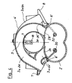
- the intake manifold system shown in FIGS. 1 and 2 is intended for a V8 internal combustion engine which has two parallel cylinder rows A and B with cylinders Z and cylinder heads Aa and Bb.
- An intake port K controlled by an intake valve V is provided in the cylinder heads for each cylinder.
- the intake manifold has a manifold 1, a suction manifold 2 adjoining this and individual suction pipes 3a-3d and 3e-3h arranged next to one another, which lead to the individual cylinders of the internal combustion engine.
- the individual intake pipes 3a - 3d supply the cylinders of one row of cylinders and the individual intake pipes 3e - 3h supply the cylinders of the other row of cylinders.
- the manifold 1 and the individual suction pipes 3a - 3h are combined to form a one-piece unit 4, which has a flange 5 or 6 on each side of its longitudinal center plane 9, from which the individual suction pipes 3a - 3d or 3e - 3h originate.
- the individual intake pipes extend in an arc over approximately 150 ° from their flange 5 or 6 to a connecting flange 7 or 8, with which the unit is screwed to the cylinder heads of the two rows of cylinders.
- the manifold 1 extends practically through the space enclosed by the individual suction pipes 3 and does not require its own space.
- the individual intake pipes 3 are arranged next to one another, with an individual intake pipe for a cylinder of one row of cylinders following an individual intake pipe of a cylinder of the other row of cylinders.
- an intermediate flange 11 is arranged between the unit -4 and the intake manifold 2, to which the intake manifold 2 is flanged and which is screwed with it to the housing of the internal combustion engine.
- This intermediate flange 11 is provided with flat surfaces 12, 13 on which the unit 4 rests with its flanges 5, 6 and which are provided with an opening 14 for each individual suction pipe 3a-3h.
- Each opening 14 is surrounded in front of a sealing ring 15, and the unit 4 is when screwing the flanges 7, 8 to the cylinder heads pressed on the seals 15.
- the intermediate flange 11 with the unit 4 - can consist of one piece.
- the intake manifold 2 extends over the entire length of the unit 4 and is closed at its right end in FIG. 2 and at its left end in FIG. 2 via a throttle valve part 16 in connection with the manifold 1.
- a throttle valve 16a is arranged in the throttle valve part 16 for each row of cylinders.
- the collecting suction pipe 1 forms a smooth cylindrical air duct at least in the right section, so that a calmed air flow can occur in this area. It is therefore possible to arrange an air quantity measuring device 18 for a fuel injection system in this area, in which a calm flow is essential for achieving correct measurement results. This is the case with hot wire air flow meters, hot foil air flow meters and the like. Due to the possibility of arranging this air quantity measuring device 18 in the unit 10, the otherwise necessary own pipe socket for accommodating the air quantity measuring device, which is attached to the suction pipe and takes up additional space, is unnecessary. To mount the air quantity measuring device 18, an opening opening into the collecting suction pipe 1 is provided in the wall of the unit 10 between two adjacent single suction pipes, which opening is indicated at 19 in FIG. 2.
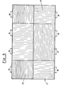
- FIG. 3 this division of the intake manifold is shown schematically, namely the subspace 22 is horizontal and the subspace 24 is hatched vertically.
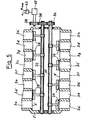
- FIGS. 4 and 5 differs from the first exemplary embodiment essentially only in that, in addition to each individual suction pipe 3a to 3h, a second shorter individual suction pipe 3a 'to 3h' is provided. While the (first) individual suction pipes 3a to 3d proceed from the first flange 5 'as in the first example, the second individual suction pipes 3a' to 3d 'assigned to them start from the second flange 6' and open into the first individual suction pipes 3a to 3d of the connecting flange 7.
- the second individual suction pipes 3d 'to 3h' assigned to the (first) individual suction pipes 3d to 3h start from the first flange 5, while these first individual suction pipes 3e to 3h start from the second flange 6.
- the mouth of every second individual suction pipe 3a 'to 3h is controlled by a rotary valve.
- the rotary valves which are assigned to the second individual suction pipes 3a 'to 3d' emanating from the second flange 6 are denoted by 26, and the rotary valves which are associated with the second individual suction pipes 3e 'to 3h' emanating from the first flange 5 are identified by 28 be draws.
- the rotary valves 26 are arranged on a first common shaft 30 and the rotary valves 28 are arranged on a second common shaft 32.
- the shafts 30 and 32 extend in the longitudinal direction of the unit 4 'and are mounted in the wall of the intake manifold 2'. The partitions in the intake manifold have been omitted for clarity.
- the shafts 30 and 32 are rotatably connected to one another by gear wheels 34 and 36.
- a drive pinion 38 engages in the gear wheel 36 and can be driven by a pneumatic or hydraulic servomotor or an electric motor 40 in order to rotate the shafts 30 and 32 together and thereby pivot all the rotary valves 26 and 28 together. In the position shown in FIGS.
- the rotary slide valves 26, 28 shut off the associated second individual suction pipes 3a 'to 3h', so that, as in the first exemplary embodiment, only the first individual suction pipes 3a to 3h are effective.
- the length of the first individual intake manifolds creates a not inconsiderable flow resistance, which cuts the maximum output. Therefore, from a certain machine speed, for example from 3,500 rpm, the rotary valves 26 and 28 are opened so that the intake air streams can now predominantly reach the individual cylinders via the short second individual intake pipes 3a 'to 3h'. This significantly increases the maximum power at full load.
- the motor 40 pivoting the rotary valve 26, 28 can be controlled by a control unit 42, in which a map with the speed and the load (medium pressure) of the internal combustion engine are stored as parameters and which open and close the rotation in this way slide 26, 28 causes the most favorable flow conditions for the intake air, for example in the area of the injection nozzles, to be achieved at any speed and load. Both a partially and fully open position of the rotary valve is possible.
- the motor 40 is preferably an electric motor, which can be pole-changeable in order to be able to carry out both the opening and the closing movement of the rotary valve.
- a double-acting pneumatic or hydraulic motor can also be used, which acts in the opening or closing direction depending on the loading.
- the rotary slide valve can be acted upon in the closing direction by a spring, not shown, so that the motor 40 only causes the opening movement and the rotary slide valve can be brought into its closed position by the spring after the motor has been shut down.
- the invention is not limited to the exemplary embodiments shown, but can also be used in multi-cylinder internal combustion engines with only one row of cylinders. In this case, only a flange 5 or 6 is provided, from which the individual suction pipes originate.
Landscapes
- Engineering & Computer Science (AREA)
- Chemical & Material Sciences (AREA)
- Combustion & Propulsion (AREA)
- Mechanical Engineering (AREA)
- General Engineering & Computer Science (AREA)
- Physics & Mathematics (AREA)
- Analytical Chemistry (AREA)
- Fluid Mechanics (AREA)
- Manufacturing & Machinery (AREA)
- Geometry (AREA)
- Health & Medical Sciences (AREA)
- Biomedical Technology (AREA)
- Characterised By The Charging Evacuation (AREA)
- Cylinder Crankcases Of Internal Combustion Engines (AREA)
- Control Of Throttle Valves Provided In The Intake System Or In The Exhaust System (AREA)
- Exhaust-Gas Circulating Devices (AREA)
Applications Claiming Priority (2)
| Application Number | Priority Date | Filing Date | Title |
|---|---|---|---|
| DE3437102 | 1984-10-10 | ||
| DE19843437102 DE3437102A1 (de) | 1984-10-10 | 1984-10-10 | Saugrohranlage fuer mehrzylinder-brennkraftmaschinen |
Publications (2)
| Publication Number | Publication Date |
|---|---|
| EP0177794A1 true EP0177794A1 (fr) | 1986-04-16 |
| EP0177794B1 EP0177794B1 (fr) | 1988-04-20 |
Family
ID=6247517
Family Applications (1)
| Application Number | Title | Priority Date | Filing Date |
|---|---|---|---|
| EP85111553A Expired EP0177794B1 (fr) | 1984-10-10 | 1985-09-12 | Dispositif d'admission pour moteurs polycylindriques |
Country Status (4)
| Country | Link |
|---|---|
| US (1) | US4643138A (fr) |
| EP (1) | EP0177794B1 (fr) |
| JP (1) | JPS6196167A (fr) |
| DE (2) | DE3437102A1 (fr) |
Cited By (22)
| Publication number | Priority date | Publication date | Assignee | Title |
|---|---|---|---|---|
| EP0200930A1 (fr) * | 1985-05-09 | 1986-11-12 | Dr.Ing.h.c. F. Porsche Aktiengesellschaft | Système d'admission d'air pour moteur à combustion interne à pistons alternatifs |
| EP0201180A1 (fr) * | 1985-05-04 | 1986-11-12 | Austin Rover Group Limited | Collecteur d'admission pour moteurs à combustion interne en V |
| EP0215628A3 (en) * | 1985-09-09 | 1988-04-20 | Honda Giken Kogyo Kabushiki Kaisha | Intake manifold assembly for engine |
| FR2613428A1 (fr) * | 1987-03-30 | 1988-10-07 | Peugeot | Moteur alimente par injection, a circuit d'admission perfectionne |
| DE3820643A1 (de) * | 1988-06-18 | 1989-12-21 | Audi Ag | Saugrohr fuer eine brennkraftmaschine |
| DE3921081A1 (de) * | 1989-06-28 | 1991-01-10 | Audi Ag | Saugrohranlage fuer eine mehrzylinder-brennkraftmaschine |
| EP0413213A1 (fr) * | 1989-08-18 | 1991-02-20 | Yamaha Hatsudoki Kabushiki Kaisha | Moteur à combustion interne de type en V |
| DE3940486A1 (de) * | 1989-12-07 | 1991-06-13 | Audi Ag | Resonanz-ansaugsystem fuer eine mehrzylinder-brennkraftmaschine |
| WO1993000505A3 (fr) * | 1991-06-24 | 1993-03-18 | Lotus Car | Collecteur d'admission pour un moteur a combustion interne a plusieurs cylindres |
| DE4228334A1 (de) * | 1992-08-26 | 1994-03-03 | Audi Ag | Saugrohranlage für eine Mehrzylinder-Brennkraftmaschine |
| WO1995018295A1 (fr) * | 1993-12-24 | 1995-07-06 | Audi Ag | Ensemble collecteur d'admission pour moteur a combustion interne a plusieurs cylindres |
| EP0691461A1 (fr) | 1994-07-05 | 1996-01-10 | FILTERWERK MANN & HUMMEL GMBH | Système d'admission pour un moteur à combustion à plusieurs cylindres |
| EP0722042A3 (fr) * | 1995-01-14 | 1996-07-24 | Yamaha Motor Co Ltd | |
| DE19528014A1 (de) * | 1995-07-31 | 1997-02-06 | Bayerische Motoren Werke Ag | Sauganlage für eine Brennkraftmaschine der V-Bauart |
| WO1996041944A3 (fr) * | 1995-06-13 | 1997-02-13 | Mann & Hummel Filter | Module de tuyau |
| WO1997023714A1 (fr) * | 1995-12-21 | 1997-07-03 | Siemens Aktiengesellschaft | Systeme d'aspiration d'air a longueur variable du tuyau d'aspiration pour moteur a combustion interne |
| EP0801224A3 (fr) * | 1992-08-31 | 1998-04-15 | Hitachi, Ltd. | Dispositif d'admission d'air pour moteur à combustion interne |
| WO1999020879A2 (fr) | 1997-10-21 | 1999-04-29 | Filterwerk Mann + Hummel Gmbh | Tambour d'ouverture ou de fermeture |
| USRE37269E1 (en) | 1992-08-31 | 2001-07-10 | Hitachi, Ltd. | Air intake arrangement for internal combustion engine |
| EP1422415A3 (fr) * | 1999-03-08 | 2005-05-18 | MAHLE Filtersysteme GmbH | Dispositif d'admission pour un moteur à combustion interne |
| DE202005012434U1 (de) * | 2005-08-04 | 2006-12-07 | Mann + Hummel Gmbh | Saugrohranlage mit einem Resonanzbehälter |
| WO2008017919A1 (fr) * | 2006-08-07 | 2008-02-14 | Toyota Jidosha Kabushiki Kaisha | Dispositif à admission variable pour un moteur à combustion interne du type en v |
Families Citing this family (27)
| Publication number | Priority date | Publication date | Assignee | Title |
|---|---|---|---|---|
| JPS62237028A (ja) * | 1986-04-08 | 1987-10-17 | Mazda Motor Corp | V型エンジンのシリンダヘツドカバ−構造 |
| DE3621490C1 (en) * | 1986-06-27 | 1988-01-14 | Audi Ag | Intake manifold system for an internal combustion engine |
| US4848281A (en) * | 1987-11-30 | 1989-07-18 | Mccord Ronald R | Pulse chamber and supercharging apparatus for internal combustion engines |
| US5016579A (en) * | 1989-02-17 | 1991-05-21 | Yamaha Hatsudoki Kabushiki Kaisha | Intake system for V type engine |
| US4919086A (en) * | 1989-02-22 | 1990-04-24 | Siemens-Bendix Automotive Electronics Ltd. | Integrated tuned induction system |
| JP2742809B2 (ja) * | 1989-02-28 | 1998-04-22 | マツダ株式会社 | 多気筒エンジンの吸気装置 |
| JP2724741B2 (ja) * | 1989-03-09 | 1998-03-09 | 本田技研工業株式会社 | 多気筒内燃機関の吸気装置 |
| US4922863A (en) * | 1989-04-18 | 1990-05-08 | Tecumseh Products Company | Cast engine cylinder having an internal passageway and method of making same |
| US4969263A (en) * | 1989-04-18 | 1990-11-13 | Tecumseh Products Company | Method of making a cast engine cylinder having an internal passageway |
| JPH0656104B2 (ja) * | 1989-05-29 | 1994-07-27 | 本田技研工業株式会社 | 多気筒内燃機関の吸気装置 |
| US5261272A (en) * | 1989-11-06 | 1993-11-16 | General Motors Corporation | Temperature sensor for integrated induction system |
| US5003933A (en) * | 1989-11-06 | 1991-04-02 | General Motors Corporation | Integrated induction system |
| US5092285A (en) * | 1991-04-15 | 1992-03-03 | Ford Motor Company | Dual-mode induction system |
| US5273010A (en) * | 1992-08-28 | 1993-12-28 | General Motors Corporation | Intake manifold |
| US5211139A (en) * | 1992-09-08 | 1993-05-18 | Siemens Automotive Limited | Active manifold |
| US5273016A (en) * | 1992-09-30 | 1993-12-28 | Outboard Marine Corporation | Throttle lever position sensor for two-stroke fuel injected engine |
| AU668740B2 (en) * | 1992-09-30 | 1996-05-16 | Outboard Marine Corporation | Two-stroke internal combustion engine with improved air intake system |
| JPH0783132A (ja) | 1993-09-17 | 1995-03-28 | Hitachi Ltd | 内燃機関の吸気装置 |
| JPH07197865A (ja) * | 1993-12-29 | 1995-08-01 | Yamaha Motor Co Ltd | V型多気筒エンジンの吸気装置 |
| US5505170A (en) * | 1994-10-06 | 1996-04-09 | Cutler Induction Systems, Inc. | Air intake manifold |
| US5655492A (en) * | 1996-06-28 | 1997-08-12 | Basf Corporation | Labyrinth manifold |
| US5704325A (en) * | 1996-06-28 | 1998-01-06 | Basf Corporation | Stacked snail-type manifold |
| DE19626251A1 (de) * | 1996-06-29 | 1998-01-08 | Bosch Gmbh Robert | Luftführungsanlage |
| US5762036A (en) * | 1997-01-16 | 1998-06-09 | Ford Global Technologies, Inc. | Split plenum intake manifold with variable runners |
| JP3394192B2 (ja) * | 1998-09-01 | 2003-04-07 | ジー・ピー・ダイキョー株式会社 | 合成樹脂製インテークマニホールド及びその製造方法 |
| US6637397B2 (en) * | 2000-09-07 | 2003-10-28 | Borgwarner Inc. | Intake manifold for an engine |
| US6718930B2 (en) * | 2001-07-23 | 2004-04-13 | Suzuki Motor Corporation | Intake system of a V-type engine |
Citations (4)
| Publication number | Priority date | Publication date | Assignee | Title |
|---|---|---|---|---|
| DE2913264A1 (de) * | 1979-04-03 | 1980-10-23 | Daimler Benz Ag | Saugrohranordnung fuer eine mehrzylindrige brennkraftmaschine mit mindestens vier zylindern, insbesondere acht zylindern |
| GB2117447A (en) * | 1982-03-27 | 1983-10-12 | Komatsu Mfg Co Ltd | Tuned i c engine intake system |
| EP0095251A1 (fr) * | 1982-05-24 | 1983-11-30 | General Motors Corporation | Collecteur d'aspiration en particulier chambre compacte d'aspiration pour un moteur |
| GB2121473A (en) * | 1982-06-01 | 1983-12-21 | Ford Motor Co | Intake manifold for an internal combustion engine |
Family Cites Families (9)
| Publication number | Priority date | Publication date | Assignee | Title |
|---|---|---|---|---|
| US3303832A (en) * | 1967-02-14 | High output engines | ||
| US2916027A (en) * | 1956-12-28 | 1959-12-08 | Gen Motors Corp | Charge forming means |
| US2845911A (en) * | 1957-08-28 | 1958-08-05 | Gen Motors Corp | Induction system |
| AT253305B (de) * | 1962-12-17 | 1967-04-10 | Hans Dipl Ing Dr Techn List | Ansaugeinrichtung bei Brennkraftmaschinen |
| GB1442247A (en) * | 1973-09-06 | 1976-07-14 | Daimler Benz Ag | Fou-stroke internal-combustion engine |
| JPS5472218U (fr) * | 1977-10-31 | 1979-05-23 | ||
| DE2930697A1 (de) * | 1979-07-28 | 1981-02-12 | Daimler Benz Ag | Saugrohranlage fuer mehrzylindrige brennkraftmaschinen |
| US4425881A (en) * | 1981-10-02 | 1984-01-17 | Aero Power Engine Manufacturing, Inc. | Reciprocating engine air intake system |
| US4446823A (en) * | 1981-11-13 | 1984-05-08 | Toyota Jidosha Kabushiki Kaisha | Internal combustion engine passage construction with intake tubes extending along surge tank wall |
-
1984
- 1984-10-10 DE DE19843437102 patent/DE3437102A1/de active Granted
-
1985
- 1985-09-12 DE DE8585111553T patent/DE3562285D1/de not_active Expired
- 1985-09-12 EP EP85111553A patent/EP0177794B1/fr not_active Expired
- 1985-10-03 JP JP60221117A patent/JPS6196167A/ja active Granted
- 1985-10-10 US US06/785,964 patent/US4643138A/en not_active Expired - Lifetime
Patent Citations (4)
| Publication number | Priority date | Publication date | Assignee | Title |
|---|---|---|---|---|
| DE2913264A1 (de) * | 1979-04-03 | 1980-10-23 | Daimler Benz Ag | Saugrohranordnung fuer eine mehrzylindrige brennkraftmaschine mit mindestens vier zylindern, insbesondere acht zylindern |
| GB2117447A (en) * | 1982-03-27 | 1983-10-12 | Komatsu Mfg Co Ltd | Tuned i c engine intake system |
| EP0095251A1 (fr) * | 1982-05-24 | 1983-11-30 | General Motors Corporation | Collecteur d'aspiration en particulier chambre compacte d'aspiration pour un moteur |
| GB2121473A (en) * | 1982-06-01 | 1983-12-21 | Ford Motor Co | Intake manifold for an internal combustion engine |
Cited By (31)
| Publication number | Priority date | Publication date | Assignee | Title |
|---|---|---|---|---|
| EP0201180A1 (fr) * | 1985-05-04 | 1986-11-12 | Austin Rover Group Limited | Collecteur d'admission pour moteurs à combustion interne en V |
| US4726329A (en) * | 1985-05-04 | 1988-02-23 | Austin Rover Group Limited | Inlet manifold for V-configuration internal combustion engines |
| EP0200930A1 (fr) * | 1985-05-09 | 1986-11-12 | Dr.Ing.h.c. F. Porsche Aktiengesellschaft | Système d'admission d'air pour moteur à combustion interne à pistons alternatifs |
| EP0215628A3 (en) * | 1985-09-09 | 1988-04-20 | Honda Giken Kogyo Kabushiki Kaisha | Intake manifold assembly for engine |
| FR2613428A1 (fr) * | 1987-03-30 | 1988-10-07 | Peugeot | Moteur alimente par injection, a circuit d'admission perfectionne |
| DE3820643A1 (de) * | 1988-06-18 | 1989-12-21 | Audi Ag | Saugrohr fuer eine brennkraftmaschine |
| US5156117A (en) * | 1989-06-28 | 1992-10-20 | Audi A.G. | Suction pipe arrangement for a multicylinder internal combustion engine with two banks of cylinders in v formation |
| DE3921081A1 (de) * | 1989-06-28 | 1991-01-10 | Audi Ag | Saugrohranlage fuer eine mehrzylinder-brennkraftmaschine |
| WO1991000419A1 (fr) * | 1989-06-28 | 1991-01-10 | Audi Ag | Collecteur d'admission pour moteurs a combustion interne a cylindres multiples ayant deux lignes de cylindres en v |
| EP0413213A1 (fr) * | 1989-08-18 | 1991-02-20 | Yamaha Hatsudoki Kabushiki Kaisha | Moteur à combustion interne de type en V |
| DE3940486A1 (de) * | 1989-12-07 | 1991-06-13 | Audi Ag | Resonanz-ansaugsystem fuer eine mehrzylinder-brennkraftmaschine |
| WO1993000505A3 (fr) * | 1991-06-24 | 1993-03-18 | Lotus Car | Collecteur d'admission pour un moteur a combustion interne a plusieurs cylindres |
| DE4228334A1 (de) * | 1992-08-26 | 1994-03-03 | Audi Ag | Saugrohranlage für eine Mehrzylinder-Brennkraftmaschine |
| WO1994004803A1 (fr) * | 1992-08-26 | 1994-03-03 | Audi Ag | Ensemble collecteur d'admission pour moteurs a combustion interne a cylindres multiples |
| US5492088A (en) * | 1992-08-26 | 1996-02-20 | Audi Ag | Intake pipe system for a multicylinder internal combustion engine |
| EP0801224A3 (fr) * | 1992-08-31 | 1998-04-15 | Hitachi, Ltd. | Dispositif d'admission d'air pour moteur à combustion interne |
| USRE37269E1 (en) | 1992-08-31 | 2001-07-10 | Hitachi, Ltd. | Air intake arrangement for internal combustion engine |
| WO1995018295A1 (fr) * | 1993-12-24 | 1995-07-06 | Audi Ag | Ensemble collecteur d'admission pour moteur a combustion interne a plusieurs cylindres |
| EP0691461A1 (fr) | 1994-07-05 | 1996-01-10 | FILTERWERK MANN & HUMMEL GMBH | Système d'admission pour un moteur à combustion à plusieurs cylindres |
| US5657727A (en) * | 1995-01-14 | 1997-08-19 | Yamaha Hatsudoki Kabushiki Kaisha | V-type engine induction system |
| EP0722042A3 (fr) * | 1995-01-14 | 1996-07-24 | Yamaha Motor Co Ltd | |
| WO1996041944A3 (fr) * | 1995-06-13 | 1997-02-13 | Mann & Hummel Filter | Module de tuyau |
| DE19528014A1 (de) * | 1995-07-31 | 1997-02-06 | Bayerische Motoren Werke Ag | Sauganlage für eine Brennkraftmaschine der V-Bauart |
| DE19528014B4 (de) * | 1995-07-31 | 2010-08-12 | Bayerische Motoren Werke Aktiengesellschaft | Sauganlage für eine Brennkraftmaschine der V-Bauart |
| US5979389A (en) * | 1995-12-21 | 1999-11-09 | Siemens Aktiengesellschaft | Air-intake device having variable induction-pipe length for an internal combustion engine |
| WO1997023714A1 (fr) * | 1995-12-21 | 1997-07-03 | Siemens Aktiengesellschaft | Systeme d'aspiration d'air a longueur variable du tuyau d'aspiration pour moteur a combustion interne |
| WO1999020879A2 (fr) | 1997-10-21 | 1999-04-29 | Filterwerk Mann + Hummel Gmbh | Tambour d'ouverture ou de fermeture |
| EP1422415A3 (fr) * | 1999-03-08 | 2005-05-18 | MAHLE Filtersysteme GmbH | Dispositif d'admission pour un moteur à combustion interne |
| DE202005012434U1 (de) * | 2005-08-04 | 2006-12-07 | Mann + Hummel Gmbh | Saugrohranlage mit einem Resonanzbehälter |
| WO2008017919A1 (fr) * | 2006-08-07 | 2008-02-14 | Toyota Jidosha Kabushiki Kaisha | Dispositif à admission variable pour un moteur à combustion interne du type en v |
| US8065982B2 (en) | 2006-08-07 | 2011-11-29 | Toyota Jidosha Kabushiki Kaisha | Variable intake apparatus for V-type internal combustion engine |
Also Published As
| Publication number | Publication date |
|---|---|
| JPS6196167A (ja) | 1986-05-14 |
| DE3437102C2 (fr) | 1987-10-29 |
| DE3437102A1 (de) | 1986-04-10 |
| JPH0154544B2 (fr) | 1989-11-20 |
| DE3562285D1 (en) | 1988-05-26 |
| US4643138A (en) | 1987-02-17 |
| EP0177794B1 (fr) | 1988-04-20 |
Similar Documents
| Publication | Publication Date | Title |
|---|---|---|
| EP0177794B1 (fr) | Dispositif d'admission pour moteurs polycylindriques | |
| DE2858176C2 (fr) | ||
| DE102007033675A1 (de) | Abgasrückführvorrichtung für eine Verbrennungskraftmaschine | |
| EP0389834A1 (fr) | Arrangement des conduits d'admission pour un moteur à combustion à plusieurs cylindres | |
| EP0645530A1 (fr) | Moteur à combustion interne avec système d'admission d'air | |
| DE4117466A1 (de) | Ansaugsystem fuer eine mehrzylinder-brennkraftmaschine | |
| DE4209155C2 (de) | Auspuffsystem für einen Verbrennungsmotor | |
| DE2530592C2 (de) | Vorrichtung zur weiteren Aufbereitung von Brennstoff-Luft-Gemischen für eine Brennkraftmaschine | |
| DE3737826A1 (de) | Verfahren zur nachladung eines verbrennungsmotors der kolbenbauart und vorrichtung zur durchfuehrung des verfahrens | |
| DE102005031393B4 (de) | Variabler Einlasskrümmer mit einem Steuerventil zur Resonanzabstimmung in drei Betriebsarten | |
| DE3940486A1 (de) | Resonanz-ansaugsystem fuer eine mehrzylinder-brennkraftmaschine | |
| DE3200521C2 (fr) | ||
| DE4110597C2 (de) | Ansaugluft-Einlasssystem für eine Mehrzylinder-Brennkraftmaschine | |
| EP0204687B1 (fr) | Moteur à combustion interne à deux temps | |
| DE3337518C2 (fr) | ||
| EP0848145B1 (fr) | Système d'admission pour moteur à combustion du type en V | |
| DE2552496A1 (de) | Verbrennungskraftmaschine mit einem gemeinschaftlichen ventilkipphebel fuer beide ventile eines zylinders | |
| AT404162B (de) | Schaltelement für brennkraftmaschinen | |
| DE3137471C2 (fr) | ||
| DE102008024571A1 (de) | Abgasrückführvorrichtung für eine Verbrennungskraftmaschine | |
| DE3728176C2 (de) | Drehschieber zur Ladungswechselsteuerung einer Brennkraftmaschine | |
| DE522096C (de) | Vielzylinderbrennkraftmaschine | |
| DE534458C (de) | Ansaugleitung fuer Brennkraftmaschinen mit zwei Zylinderreihen | |
| DE3519143A1 (de) | Hubkolben-brennkraftmaschine | |
| DE19612036A1 (de) | Saugrohranlage für eine mehrzylindrige Brennkraftmaschine in V-Anordnung |
Legal Events
| Date | Code | Title | Description |
|---|---|---|---|
| PUAI | Public reference made under article 153(3) epc to a published international application that has entered the european phase |
Free format text: ORIGINAL CODE: 0009012 |
|
| AK | Designated contracting states |
Kind code of ref document: A1 Designated state(s): DE FR GB IT |
|
| 17P | Request for examination filed |
Effective date: 19861002 |
|
| 17Q | First examination report despatched |
Effective date: 19870309 |
|
| GRAA | (expected) grant |
Free format text: ORIGINAL CODE: 0009210 |
|
| AK | Designated contracting states |
Kind code of ref document: B1 Designated state(s): DE FR GB IT |
|
| REF | Corresponds to: |
Ref document number: 3562285 Country of ref document: DE Date of ref document: 19880526 |
|
| ITF | It: translation for a ep patent filed | ||
| ET | Fr: translation filed | ||
| GBT | Gb: translation of ep patent filed (gb section 77(6)(a)/1977) | ||
| PLBE | No opposition filed within time limit |
Free format text: ORIGINAL CODE: 0009261 |
|
| STAA | Information on the status of an ep patent application or granted ep patent |
Free format text: STATUS: NO OPPOSITION FILED WITHIN TIME LIMIT |
|
| 26N | No opposition filed | ||
| ITTA | It: last paid annual fee | ||
| PGFP | Annual fee paid to national office [announced via postgrant information from national office to epo] |
Ref country code: DE Payment date: 19960809 Year of fee payment: 12 |
|
| PGFP | Annual fee paid to national office [announced via postgrant information from national office to epo] |
Ref country code: GB Payment date: 19960819 Year of fee payment: 12 |
|
| PGFP | Annual fee paid to national office [announced via postgrant information from national office to epo] |
Ref country code: FR Payment date: 19960906 Year of fee payment: 12 |
|
| PG25 | Lapsed in a contracting state [announced via postgrant information from national office to epo] |
Ref country code: GB Free format text: LAPSE BECAUSE OF NON-PAYMENT OF DUE FEES Effective date: 19970912 |
|
| PG25 | Lapsed in a contracting state [announced via postgrant information from national office to epo] |
Ref country code: FR Free format text: THE PATENT HAS BEEN ANNULLED BY A DECISION OF A NATIONAL AUTHORITY Effective date: 19970930 |
|
| GBPC | Gb: european patent ceased through non-payment of renewal fee |
Effective date: 19970912 |
|
| PG25 | Lapsed in a contracting state [announced via postgrant information from national office to epo] |
Ref country code: DE Free format text: LAPSE BECAUSE OF NON-PAYMENT OF DUE FEES Effective date: 19980603 |
|
| REG | Reference to a national code |
Ref country code: FR Ref legal event code: ST |